Using 3D Geometry
Creating geometry is usually the most frustrating part of developing a 3D scene. Java 3D provides utilities for making basic geometric elements (for example, the Box used in our examples so far) and many scenes can be developed using these supplied elements. It is recommended that the beginning Java 3D programmer begin with these and not get too bogged down laying out vertices and faces (although doing so is enlightening). A brief summary of the geometry classes follows, but before that we should examine the basic elements of developing geometry in, or as will be seen shortly, for Java 3D.
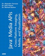
The reason we emphasize creating geometry for Java 3D is that it is possible and sometimes highly desirable to use a third-party package to develop the geometry for a scene. Additionally, it is easy to find pre-existing geometric objects on the Internet. Finally, the developer might be restricted to using 3D models of a particular kind. For example, the 3D model of a human subject's cerebral cortex shown in Figure 11.6 was made more easily using a third-party package and then output as .OBJ. More information on the Loader interface is provided in the section “Using Loaders.”
Figure 11.6. 3D model of a human brain derived from MRI images.

Java 3D provides all the classes necessary to create geometry and in most cases offers a lot more flexibility than using loaders.
In developing an application that requires more than simple geometry, the programmer is always faced with a choice—to either program the geometry using the Java 3D classes or to build the geometry in another package and import it. Often a hybrid approach is optimal.
Following a description of using simple geometry, we will compare these two approaches and examine the tradeoffs therein.
Making Simple Geometry with the Java 3D Utilities
Java 3D provides several classes for the creation of some basic geometric primitives. These are often sufficient to get the programmer started with some simple examples and indeed can be used in more complex cases as well. You will see, throughout this chapter, that often the supplied geometric primitives aren't sufficient for many jobs. Therefore, geometry needs to be either custom programmed or alternatively imported from a third-party package in many cases.
The Java 3D geometry classes are found in com.sun.j3d.utils.geometry and, with the exception of the ColorCube class, all extend another supplied class called Primitive. Primitive extends Group. As mentioned in Chapter 10, it can be useful to examine these classes by unjarring the Java 3D-utils-src.jar file. Remember to copy this file to a new directory before unjarring it. After unjarring, it is possible to see how the Java 3D architects built various utilities such as the Box class described next.
Although the geometry classes are indeed very useful, you will see shortly that they certainly don't satisfy all of our geometric modeling needs. In those cases, it is necessary to either program the geometry or to use a loader. We begin with the simple geometry classes before addressing the more complicated topic of programming geometry and geometry loaders.
The Box Class
Four constructors are used to create a Box. The three most commonly used are
Public Box(); Public Box(float xdimension, float ydimension, float zdimension, Appearance appearance); Public Box(float xdimension, float ydimension, float zdimension, Appearance appearance,int Capability);
There are five constructors for the Cone class; all of which require a radius for the base and length. Note that the number of divisions is specified in the radial direction.
Public Cone(); Public Cone(float radius, float length) Public Cone(float radius, float length, Appearance appearance); Public Cone(float radius, float length, int Capability, Appearance appearance); Public Cone(float radius, float length, int Capability, Appearance appearance, int
The Cylinder Class
Like all cylinders, the Cylinder class defines a tube with a radius and height. An object instantiated from this class is centered at the origin and aligned with the Y axis. The most common constructors are
Public Cylinder(); Public Cylinder(float radius, float height) Public Cone(float radius, float height, Appearance appearance); Public Cone(float radius, float height, int Capability, Appearance appearance); Public Cone(float radius, float height, int Capability, Appearance appearance, int
The Sphere Class
As you would expect, the Sphere class produces a ball with a given radius.
Public Cylinder();
Public Cylinder(float radius)
Public Cylinder(float radius, Appearance appearance);
Public Cone(float radius, int Capability, Appearance appearance);
Public Cone(float radius,  int Capability, Appearance appearance, int ndivisions);
Specifying the Appearance Bundle
Creating the geometry using the provided Java 3D utility classes is pretty easy because a number of important details were taken care of without our knowledge. One of the important things that occurs behind the scenes is the creation of a Material and an Appearance for the object. Note, however, that you can specify your own Appearance object in all the utility geometry constructors.
At this point, you should keep in mind that the Shape3D class contains both a Geometry object and an Appearance object (also known as an Appearance bundle).
Programming Geometry in Java 3D
The central class for creating geometry in Java 3D is Shape3D. In its most general form, a Shape3D object is a list of Geometry objects with an Appearance bundle. For now, we will focus on the geometry contained in the Shape3D node and defer a detailed discussion of the Appearance bundle until later. The geometry components are listed in Table 11.3 and are all subclasses of Geometry.
To reiterate, a Shape3D is a collection of geometry components that reference a single Appearance object. We will now describe the geometry components listed in Table 11.3.
We begin with the GeometryArray class, which represents a collection of geometric primitives. Table 11.4 shows a list and description of the allowable primitives.
The classes listed in Table 11.4 fall into three broad categories, strip-based geometry, indexed-based geometry, and basic vertex specification type geometry.
Strip-based Geometry
When one specifies geometry in strips, it is similar to building a model with long strips of cardboard or paper. The important thing to note about strip-based geometry is that there needs to be an index that specifies which elements belong to which strip. Table 11.5 shows the strip-based geometry classes. The classic example of strip-based geometry is a cocktail umbrella. Each of the umbrella's triangles meets in the center and shares two edges with its neighbors. This is exactly the way to format the data in a triangle fan array.
Index-based Geometry
The IndexedGeometryArray is really an array of four vectors specifying the position coordinates, colors, normals, and texture coordinates for each primitive. Not all of these are necessarily specified. For example, in the class in Listing 11.6, only the position coordinates are specified. A series of bitmasks can be queried in order to find out which combinations of the four vectors have been specified. The IndexedGeometryArray classes are essentially index-based version of the classes specified in Table 11.4 with the prefix Index attached. We defer discussion until the examples later in this chapter.
Programming Example with Simple Vertex-based Geometry
We begin our examples of programming geometry by using the simplest Geometry class, the PointArray. The simplicity of this class makes it a good choice for gaining a basic understanding of the operations involved in programming geometry.
The PointCloud class (see Listing 11.6) generates n random 3D coordinates and puts them in a PointArray.
Listing 11.6 PointCloud.java
import javax.media.j3d.*;
import javax.vecmath.*;
import java.util.Random;
public class PointCloud {
float verts[];
Point3f[] rCoords;
Random r;
PointArray points = null;
Shape3D shape;
public PointCloud(int npoints, float x, float z, Appearance a) {
r = new Random();
genRandomCoordinates(npoints, spread);
Appearance app = new Appearance();
points = new PointArray(npoints, PointArray.COORDINATES);
points.setCoordinates(0, rCoords);
shape = new Shape3D(points, app);
}
public void genRandomCoordinates(int npoints, int spread) {
for (int ii=1; ii <= npoints; ii++) {
rCoords[ii] = new Point3f(r.nextFloat()*spread, r.nextFloat()*spread, r.
|
Let's take a deeper look at this class. The first thing to notice is that the class is a bit unusual because it doesn't extend any Java 3D classes. Other than the constructor, the PointCloud class has two methods. The first method, genRandomCoordinates(), generates random 3D points using the nextFloat() method of the Random class. Note that each Float value is multiplied by the float spread in order to spread the points out (nextFloat() generates numbers [0,1.0]. Each Point3f is stored in a one dimensional array rCoords. After rCoords is generated, it is used as an argument to the setCoordinates() method of our PointArray. The genRandomCoordinates() method isn't standard because it uses the random() method to generate the points. Usually, the coordinates represent a known object and must be specified.
The second method simply returns the shape that was just created in the constructor. This is the method that the calling class will use to get the Shape3D object into the scene. We therefore add the following from our standard createScene() method:
PointCloud pc = new PointCloud(10000);geoTG.addChild(pc.getShape());
The class in Listing 11.6 follows the standard recipe for creating a Shape3D. In this case, only the vertices are specified. If for example, we wanted to also generate colors for each vertex, we could add a method to generate arrays of length npoints such as follows:
GenRandomColors(nponts);
points.setColors(0, rColors);
The GenRandomColors method would be the following:
public void genRandomColor(int npoints) {
   for (int jj=0; jj <  npoints; jj++) {
          rColors[jj] = new Color3f(r.nextFloat(), r.nextFloat(), r.nextFloat());
   }
}
Finally, we need to modify the creatScene() method to incorporate our random colors:
points = new PointArray(npoints, PointArray.COORDINATES | PointArray.COLOR_3);
points.setCoordinates(0, rCoords);points.setColors(0, rColors);
A related example using the point array to plot real data in 3D is given in Listing 11.21 under SpikeCloud.java in the section “ Comprehensive Example #2: Neuronal Spike Visualization.”
A Hybrid Example of Geometry Programming
The importance of the GeometryArray is such that we follow it up with another example. We will continue to expand this particular example in “Comprehensive Example #1: MR Physics Visualization.” In this case, we want to create a scalable tube with a cone at the end. This object will represent the net magnetization of a group of “spins” in a sample of brain tissue or other substance of interest. The net magnetization is a vector quantity because it has both direction and magnitude. This is different from the concept of a vector from computer science. We will increase the complexity of this object considerably as we develop it into a comprehensive example including adding the ability to shrink and grow this vector.
The first important idea is that, with the exception of the PointArray and LineArray (and their index-based relatives), Geometry objects represent surfaces. Except for explicitly bi-directional surfaces, a surface has only one side and thus can be invisible depending on the viewing direction. This can make programming them particularly challenging and prone to trial and error. You will remember that we recommend attaching one or two navigational or rotational Behaviors to the scene graph in order to avoid the danger of becoming lost in space. Using the Geometry classes is definitely a case in which having a way to move the object of ViewPlatform is beneficial. Often the developer is looking at the wrong side of the surface or is unknowingly sitting in the middle of the object.
The second important lesson from this example is that programming geometry can be tedious work. There is a particularly steep learning curve with the Geometry classes. We remind you that this advanced topic can be skimmed over for its gist and returned to later as necessary.
Finally, we take a tack slightly different from our first example and create our geometry within a class that extends TransformGroup. The reason for this is mostly academic. However, we choose this approach here because it is 1) commonly seen in examples, and 2) we intend to add children to the object and perform a series of spatial transformations on them as a group.
In this example, we create a Shape3D called vbody and add it to our class extending TransformGroup (the VecBody class). We also create a Cone object and add it to another class extending TransformGroup called VecHead. These two TransformGroup objects are then added to a higher level TransformGroup called Mnet.
We begin by showing the VecBody class (see Listing 11.7 ) because it contains the programmed Geometry.
Listing 11.7 VecBody.java
Note from the listing that we needed to create three GeometryArray objects; one each for the two endcaps of the vector body and one for the body itself. The Geometry for the endcaps is created with two successive calls to the genCaps() method. In that method, we specify a TriangleFanArray object called face and loop over the segments of the fan, specifying the vertices using the equation for a circle.
Special care must be taken when filling a GeometryArray or IndexedGeometryArray with values. The programmer must be sure to understand the proper order to specify the vertices and get the correct number of vertices for the particular class chosen.
Geometry Compression Classes
Java 3D has a number of classes for working with compressed geometry. Specifically, the CompressedGeometry class and the CompressedGeometryHeader class are used for this purpose. Geometry compression can often dramatically reduce the memory overhead associated with geometric objects. This can be particularly useful in Internet applications in which you have to send large models over limited bandwidth connections.
Like image compression methods, there is a loss of information during geometry compression. For the majority of applications, this isn't a major issue because geometric precision isn't the primary objective. However, the developer must keep these issues in mind.
Similar to the other preceding Geometry classes, the CompressedGeometry class allows geometry-by-reference and geometry-by-copy.
Using Raster Geometry
The name raster geometry is a bit confusing because the only link to a geometric primitive is that a point is used to specify the location of a 2D raster. Refer to Chapters 2–4 for the details of a Java Raster, which is basically a rectangular array of pixels (a DataBuffer plus SampleModel). In Java 3D, Raster is represented by a special utility class called ImageComponent2D.
Raster geometry is useful for presenting 2D images in the 3D environment. This can have applications for things such as placing sprite animations or text labels in the environment. An example of presenting information to the user with the Raster class is given in the Virtual Shopping Mall example in Chapter 14, “Integrating the Java Media APIs.”
Using Loaders
As already mentioned, there are a lot of good reasons to use loaders to bring in geometry from a third-party package or file format. Undoubtedly, almost everyone who writes a Java 3D application will need to use a loader sometime, and it is often desirable to mix scene elements brought in with a loader with elements programmed using the Geometry classes.
Java 3D has provided a fairly robust infrastructure for creating custom loaders, and a reasonably large number of loader's are in existence. Go to http://www.j3d.org/utilities/loaders.html for an up-to-date listing. We will focus on the general structure and use of the Loader Interface.
In general, writing or even using a loader can be a challenge for several reasons, not the least of which is that little documentation is available. Another serious challenge results from matching the version of the third-party format with the version expected by the Loader Interface.
Inside the Loader Interface
The interface to implement when writing a custom loader is defined in the following:
com.sun.j3d.loaders
A class that implements the Loader Interface is basically a file parser that reads in the file; for example, a VRML 2.0 .wrl file converts the parts of text into Java 3D objects such as lights or objects and arranges these objects into an appropriate scene graph representation.
Java 3D's New Native File Format
The separate J3DFly download allows for the serialization of scene graph objects and thus corresponds to a native file format (of sorts) for Java 3D.
To add serialization to any custom object, the programmer will need to implement the following method:
public void writeSceneGraphObject( java.io.DataOutput ) throws IOException;
The procedure for serializing is to serialize the objects using ByteArrayOutputStream, count the resulting number of bytes, and then write these bytes into the DataOutput object before calling writeSceneGraphObject.
The resulting file contains all the objects and data associated with the object being serialized. Because a serialized object contains all the associated classes, the programmer is occasionally surprised by the ultimate size of the serialized object. For example, an object load from VRML might be some three times larger after serialization. The size increase is because of the added normals, transparency values, and other components added to it.
In the utility classes, Java 3D provides an interface called LoaderBase. If you have unjarred the Java 3D utilities as recommended in Chapter 10, this would be a good time to examine the LoaderBase interface. Any loader class implements this interface. A second interface, the Scene interface, is also important.
As an example that we will revisit later, consider an .obj file that contains a list of triangles. Taking the first seven lines of the file wm.obj, we have the following:
#--------------- X1_X2_BV ---------------
v 2.940000 4.266000 6.430000
v 2.948000 4.326000 6.449000
v 2.912000 4.268000 6.500000
v 2.974000 4.395000 6.473000
v 2.943000 4.337000 6.539000
v 2.958000 4.259000 6.587000
v 3.022000 4.539000 6.506000
. . .

f 1 2 3
f 4 5 2
f 6 3 5
f 2 5 3
f 7 8 9
f 10 11 8
f 4 9 11
. . .
eof
Or alternatively in the VRML 2.0 file that we will use shortly:
#VRML V2.0 utf8
#A floor
Shape {
    geometry Box {
            size 20 0.1 30
    }

}
It is fairly easy to see how a parser could be written to recognize the first character as either a v or an f (in the case of this particular .obj file) and to construct an appropriate GeometryArray from the extracted information. Likewise for the office.wrl file, we could easily search for the string Shape and build up our scene from there. Parsing is in large part what a Loader does.
One confusing aspect of working with Loaders is that they are designed to return an object implementing the Scene interface. Listing 11.8 illustrates this point.
Listing 11.8 vrmlLoad.java
import javax.media.j3d.*;
import java.io.*;
import com.sun.j3d.loaders.vrml97.VrmlLoader;
import com.sun.j3d.loaders.Scene;

public class vrmlLoad extends BranchGroup{

    public vrmlLoad(String filename) {
      BranchGroup obj = new BranchGroup( );

      VrmlLoader loader = new VrmlLoader();
        Scene s = null;

        try{
          s = loader.load(filename);
        }
        catch (Exception e){
           System.err.println(e);
           System.exit(1);
        }

        obj.addChild(s.getSceneGroup( ) );
        this.addChild(obj);
    }
}
|
From the preceding, we can see the that the load() method of the Loader interface returns an object s of type Scene. Looking at the Scene.java code that we unjarred earlier, we can see that there are 10 methods that can be overridden when implementing Scene. The getSceneGroup() method is called in this code example because this is the most common case. However, keep in mind that it is also possible to get the lights, views, background, fog, and so on. Any particular custom Loader might or might not implement all these methods.
The question of how to access individual elements of the Scene can be tough. The following method is useful for accessing individual elements of the loaded file:
public Hashtable getNamedObjects()
The getNamedObjects returns a Hashtable of all named objects in the imported scene with their associated Java 3D scene graph object names. You can simply print or list the objects in order to find their names.
Optimizing Geometry with the GeometryInfo Class
The GeometryInfo class can be used to save a great deal of effort in modeling geometry and can also provide several methods to improve the efficient representation of a model. The basic idea is to place the geometry in a GeometryInfo object before calling Java 3D's utilities. The Java 3D utilities can help in generating normals or in stripification (the process of turning geometry into long strips for more efficient rendering).
The GeometryInfo class itself contains several other methods for improving the efficient representation of geometry. These include indexifying (that is, calculating indexes) and compacting (removing unnecessary indexes).
Getting data into GeometryInfo can be a little more challenging than loading up a GeometryArray object because there are fewer options. It often isn't necessary to work with GeometryInfo except in cases where efficiency can be improved by stripification.
3D Text
Three-dimensional text can add visual appeal to certain 3D applications. Pickable text can serve as a nice user interface method and text can be useful for annotation. In many ways, it is easier to use Java 3D's 3D text classes than making 2D text and displaying it using textures or raster geometry.
To use 3D text, specify a Point3d where the text will be placed and a reference to a Font3D object. The Font3D object contains a list of extruded 2d glyphs (see Chapters 2 and 3 for a description of glyphs).
Examples of using 3D text are found throughout the examples in this and the next several chapters.
Making Changes to Live Geometry
As you saw previously, the GeometryArray class contains lists of vertex components: coordinates, normals, colors, and texture coordinates. Each is stored in a one-dimensional array (vector). From these values, we are able to create our own geometric shapes, just as we did in our PointCloud example. Further, you have seen that we can easily perform a number of rigid body transformations (translations, rotations, and scalings) on this data. You will see later that we can even morph between two shapes.
Although these capabilities are enough to handle many problems, a game or visualization developer would want to accomplish a number of things that are difficult or even impossible to achieve using linear transformations. In these cases, the developer must make some decisions based on the application.
A couple of options exist, but they have some drawbacks. Probably, the conceptually simplest thing we could do is instantiate new geometry and add it to the scene graph, but this is a poor approach in general.
One way to make changes to the geometry is through Geometry-by-reference. Geometry-by-reference is part of the set of classes that utilizes so-called by-reference functionality that is part of Java 3D version 1.2. By-reference is a way of accessing buffered data. The buffer data can be changed as it sits in accessible memory area (much like a BufferedImage). The GeometryUpdater class can be used to update the geometry during runtime.