PROJECTS Remaking History
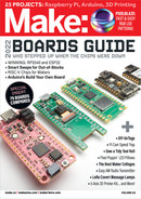
2. Use the jigsaw to make a 2½"×2½" square
cutout centered in the 3½"×3½"×¾"
escapement block. Next, drill ⁄" holes into the
center of the top and bottom of the ¾"-thick
escapement block. Glue the 1¾" squares to
the escapement block as shown.
When the glue is dry, slightly enlarge the
opening where the two 1¾" squares meet, by
cutting about ¼" off each corner (Figure
B
).
3. Cut the crutch as shown in Figure
C
, then
drill the ⁄" hole and ⁄" hole as shown.
4. Drill a ⁄" hole in the center of the 2"×2"×¼"
plywood square. Then drill a single ⁄" hole,
1" away from the center hole in any direction.
This piece is the crank.
5. Insert the ⁄" crank shaft bolt all the way into
the center hole in the 2"×2"×¼" crank, so that
it’s flush against the underside of the bolt
head. Glue into place.
Insert the #10 bolt through the ⁄" hole as
shown in Figure
D
, and glue it in place too.
This is the escapement drive pin.
6. Drill two ⁄" holes through the 2×4 frame
piece as shown in Figure A. Countersink both
ends of each hole ⁄" inches deep with the
22mm (or ⁄") Forstner bit. Insert a skateboard
bearing in each 22mm hole, front and back.
The top hole is for the pendulum shaft bolt and
the bottom is for the crank shaft bolt.
7.
Use the C-clamp to attach the frame to a
workbench. Insert the pendulum shaft bolt
through the upper hole in the frame (Figure
E
).
8. Similarly, insert the crank shaft bolt through
the lower hole in the frame.
9. Push the ⁄" hole on the crutch onto the
pendulum shaft bolt. Insert one end of the
upper pendulum into the ⁄" hole in the crutch,
and the opposite end into the hole on the top of
the escapement block. Slide the escapement
up or down on the upper pendulum until the
opening in the center of the escapement
aligns with the axis of the horizontal crank
shaft bolt. Then cut the pendulum to length.
Insert the lower pendulum into the bottom
hole on the escapement block. Use washers
as spacers to align the crank bolt so the
midpoint of the drive pin pushes against the
escapement wings when the crank turns. The
idea is that when the falling weight turns the
crank shaft, the drive pin alternately engages
the wings, which in turn pushes the pendulum
back and forth. See Figures
F
and
G
.
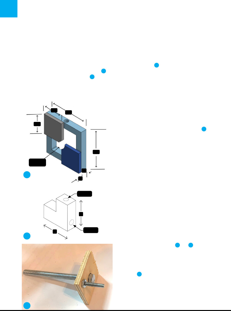
10. When you’re satisfied with the alignment,
fix all the wood-on-wood connections with
glue to prevent the parts from spinning. The
completed single pin escapement is shown in
Figure
H
.
11. Wrap the protruding crank bolt with some
tape to make a little drum. Then wrap a few
feet of twine around the drum and attach 8
ounces of weight to the free end.
Enlarged
opening
Escapement
1¾"
1¾"
3½"
3½"
¾"
¼"
102 makezine.com
B
C
D
Crutch
2"
2"
⁄" hole
⁄" hole
M83_100-103_RemHist_F1.indd 102M83_100-103_RemHist_F1.indd 102 10/11/22 10:36 AM10/11/22 10:36 AM
..................Content has been hidden....................
You can't read the all page of ebook, please click here login for view all page.