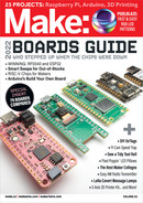

Image selector
8-position switch
Color selector
potentiometer
Send
pushbutton
3" antenna 5V power
Pixel 15
Pixel 16
Pixel 0
Pixel 255
16×16 “NeoPixel”
RGB Matrix
0.1µF
Capacitor
PROJECTS LoRa Communicator Lamp
connectors, a male and a female.The male
should be connected to the data-out, so it won’t
be used. I cut the data-out cable, plugged it into
the data-in, and soldered jumper wires to it to be
connected to the breadboard. This makes an easy
way to attach the matrix to the breadboard later.
Next, the Feather is inserted onto the
breadboard. If you have to solder the header
pins on first, insert the long side of the pins into
the breadboard, lay the Feather on top, and then
solder the pins. I created many microcontrollers
with crooked header pins before I learned that
simple trick.
Strip off about 5mm of insulation from the
wires and plug them into the breadboard
following the wiring diagram (Figure
B
). For the
8-way switch, it doesn’t matter which wire goes
to which pin at this point; it’s easier to rewrite the
code to match the proper pin to each image after
you install the switch in the enclosure. For the
ground wires, plug them into the ground rail on
the side of the breadboard. Additionally, I used a
jumper wire to connect the Feather’s GND pin to
the ground rail and soldered a 3" piece of wire on
the antenna pin to act as a simple quarter-wave
whip antenna.
You’ll need one more jumper or a diode to
connect the USB pin to the 5V rail, but don’t
connect that yet.
2. YOU’VE GOT THE POWER
Originally, my emoji designs used all 256 LEDs
on the matrix, and I had the breadboard powered
by one of those convenient breadboard power
supplies that deliver 5V or 3V to the side rails
of the breadboard. When I was showing off an
early prototype to my neighbor Pete, he pointed
out running all 256 LEDs was going to draw
over 5 amps of power (256 × 0.02A = 5.1A) and
my supply only handles a max of 0.7 amps. He
recommended scaling down the designs and
using at least a 3-amp power supply. Pete knows
math. Pete knows electronics. I listen to Pete. So,
I cut off the end of a 3A 5V USB power supply and
soldered leads to connect to the breadboard’s
power rail.
3. UPLOAD THE CODE
The Arduino program, LOL-RaLamp.ino, has three
main components: 1) displaying the images, 2)
sending and receiving the image information, and
3) displaying the partner images.
To create the images, I first designed them
using a simple 16×16 cell box in Excel. I filled
each cell with values 0 through 255; 0–15 on
the first row, 16–31 on the second, and so on.
Next, I drew the image by filling in each cell with
the color I wanted. Since the “first '' pixelof the
matrix starts in the top right corner and zigzags
B
Fritzing
96 makezine.com
M83_094-98_LoRaLamp_F1.indd 96M83_094-98_LoRaLamp_F1.indd 96 10/11/22 9:59 AM10/11/22 9:59 AM
..................Content has been hidden....................
You can't read the all page of ebook, please click here login for view all page.