
Now that you've been through each of the major parts of a game model's creation—modeling, UV Mapping, texturing, and animating—you can start making your own game environments and props. For this chapter, let's combine the techniques you've learned so far and make something that you might consider more "gamey." Although every game will need vehicles, buildings, foliage, and even industrial fans (all of which can be very fun to make!), an environment artist might be a little extra enthusiastic about some items because they require a bit more imagination. In this chapter, you'll create a science-fiction . . . thing. I'm not sure exactly what it will be yet. Let's get started, and we'll see what comes out of it!
Here's the task: Create a science-fiction prop. It can look like anything you want, but it has to have certain requirements. It must be some sort of computer/machine, it must have some sort of glow effect (preferably blue), and it must move in some way. This really is the kind of task that an artist may receive on any given project. These kinds of tasks can be very exciting and really scary all at the same time.
It can be scary to create an object like this because you might come up with something that the boss doesn't like! Many artists (me included) prefer to have a bit more concrete direction, whether it is a concept sketch or some sort of reference to another prop or even another game to look at to get some sort of guideline. The best way to alleviate these kinds of concerns is to come up with several ideas and draw them out on paper or, if you aren't that good at drawing, even mock up your ideas in Maya using simple primitives to get the idea across. Then allow your boss to pick his favorite. This way, your boss can see what direction you are going in and can quickly change your thinking or, even better, praise your direction and tell you to continue.
This can be very exciting because it allows you to have some creative control. Sure, it's just a prop, but it's your prop. And if it is liked, you could get more such responsibility in the future and have more and more creative input. And even better, it more than likely means the boss has liked your work in the past and trusts your judgment to come up with something cool!
It's time to get started.
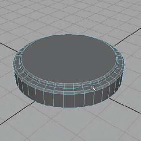
Create a short polygon cylinder and place it on the origin. Mine has about a 4 unit diameter with a height of about a half a unit. Lower the Subdivisions Caps to 0 to remove the pizza slicing faces.
Select the top face and bevel it slightly to round the edge. Select the top face again and apply an Extrude, scaling it inward to create an interior circular face on top of the cylinder.
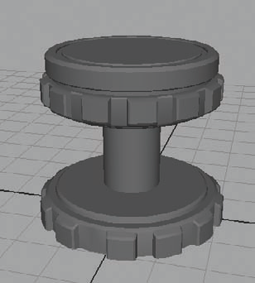
Extrude again, bringing the extrusion up, and scale it inward slightly. Apply another Bevel to the topmost face to again round the edge. This creates a round pedestal shape like you see in Figure 8.1.
Around the circumference of the pedestal, select two adjacent faces, skip a face, select the next two faces, skip a face, and so on, until you have gone around the pedestal.
Extrude the selection, pulling the faces outward to create a gear-like shape.
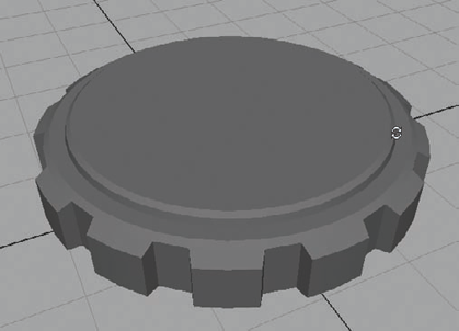
With the selection still active, go to the Side View. Press the R key to toggle the Scale Tool. Press the Insert key on the keyboard (usually near the Delete and Home keys). The scale gizmo will change, indicating that it's in Edit Pivot mode. Move the pivot handle down to be even with the base of the geometry.
Press Insert again to exit Edit Pivot mode. Be sure not to change your Scale Tool to a different tool or it will erase the pivot change. With the pivot change still active, scale down the faces, making them taper toward the base of the geometry (Figure 8.2).
Bevel the sides of the gear teeth to soften their edges. Continue to detail the pedestal however you see fit.
Once you have your pedestal detailed the way you like, duplicate it, move it up about 2.5 units, and flip it upside down.
Select the top face (what used to be the bottom) and raise it up slightly, making the gear teeth taper downward as the other side was tapered.
With the top face still selected, bevel it to get a rounded edge around the entire face. Maintaining your selection, apply an Extrude and scale the extrusion inward slightly to create an inner circular face.
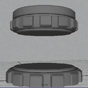
Extrude again and pull upward about a quarter of a unit's distance. Extrude once again and scale it out, creating a lip that extends out beyond the previous face.
Extrude again, pulling up just slightly and scaling outward to round off the lip's edge. One final time, extrude and pull upward about a full unit's distance and bevel the top to round the resulting hard edge. After this series of Extrudes and Bevels, you should have something resembling Figure 8.3.
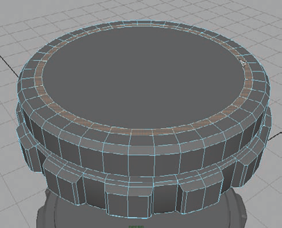
Next, you can add an indented circle around the top of the pedestal. Select the topmost face and apply an Extrude. Scale it inward, creating an inner circle on the top face. Extrude and scale inward again to create a ring around the top face, as in Figure 8.4.
Select the faces of the ring. Do this by selecting the Select Edge Ring Tool from the Select menu. Double-click an edge within the ring of geometry on the pedestal and all of the edges should be selected within the loop. Go to Select → Convert Selection → To Faces (or press Ctrl+F11). This will, obviously, convert your edge selection to faces, allowing you to select the ring of faces very easily.
With the faces of the ring selected, apply an Extrude and push them down into the pedestal, creating a groove around the surface. Select the border edges of the groove and bevel them to soften their contours.
Now that you have a top and bottom section for the pedestal you are creating, you can connect the two halves.
Create a cylinder that joins the bottom of the top half of the pedestal to the top of the bottom half of the pedestal. Decrease the Subdivisions Caps to 0 and increase the Subdivisions Axis to 40 to make the cylinder even more round.
Scale in the cylinder to make it approximately 1 unit in diameter, as you can see in Figure 8.5.
To give this cylinder a more interesting shape, you can make it appear to have the grooves of a screw cut into it. This can easily be done using a Boolean Difference operation. Create a polygon helix with these settings:
Coils
8
Height
3.5
Width
1.5
Radius
0.12
Subdivisions Axis
16
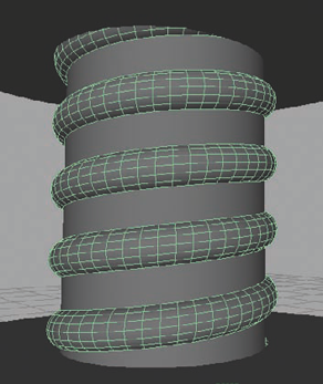
Positioning the helix around the connecting cylinder should give you a result similar to Figure 8.6. Readjust the cylinder or helix shape if you need to make some changes to get it to look like this.
Select the cylinder and Shift-select the helix. Go to Polygons → Booleans → Difference. The result should give you screw-like grooves spiraling up the surface of the cylinder.
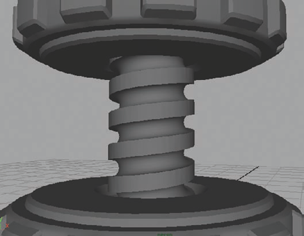
Using a combination of Extrudes and Bevels, create an indentation into the bottom half of the pedestal for the screw shape to fit into. Do the same for the bottom of the top half of the pedestal (Figure 8.7).
That helix shape was kind of interesting, wasn't it? Let's add some spiraling support structures to the pedestal to give it an otherworldly appearance.
Create another polygonal helix primitive and adjust the following:
Coils
0.5
Height
3
Width
3
Radius
0.25
Subdivisions Axis
16
This creates a shape like what you see in Figure 8.8.
Position it as you see in the above figure and place its pivot point at the origin. Duplicate it and rotate it 90 degrees. Repeat this two more times to get four spirals arrayed around the pedestal.
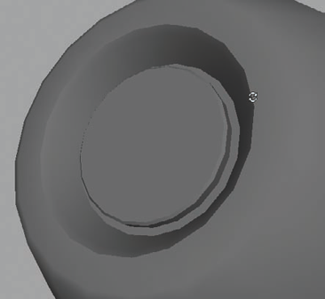
I'm thinking this pedestal will act as a hover device with some sort of futuristic doodad hovering above it. To help sell this idea, let's add a small detail to the top of the pedestal to make it appear that some sort of lens device is creating a sort of propulsion above the pedestal.
Use a combination of Extrudes and Bevels to create an indention on top of the pedestal, which gives you a spot to place a lens-like device in a later step.

Now you'll create the mysterious device that is hovering above the pedestal by means of some alien technology unheard of on Earth! Or something like that.
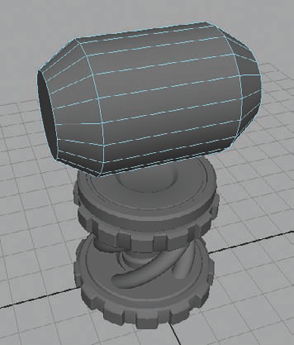
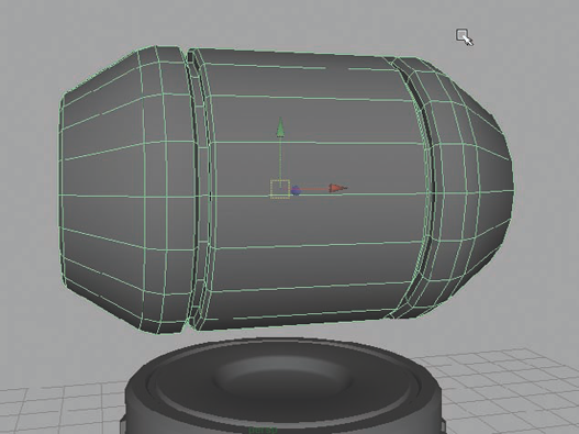
Create a cylinder that's about 2 units in diameter and about 3 units tall. Rotate it 90 degrees so that it's on its side and position it above the top of the pedestal by about 1 unit up. Decrease the Subdivisions Caps to 0.
Select the two cap faces and extrude them out about a full unit's length. Scale them inward to taper the sides of the capsule as in Figure 8.9.
Using the Select Edge Loop Tool from the Select menu, select both vertical edge loops at the base of the prior extrusions and bevel them slightly. Also bevel the two cap faces to round off their harder edges.
Select both cap faces again, if they aren't already selected. With a series of Extrudes and Bevels, create indentions on both ends of the capsule that look like the one in Figure 8.10—a rounded indentation with a small "shelf" raised inside. In a later step, you'll be adding a little window into the device on these surfaces.
Select the center faces around the middle of the canister-like object and apply an Extrude. Scale it inward along the length of the canister about a quarter of a unit.
Extrude again and push inward slightly, scaling it in as well to create a small, beveled lip. Extrude again and push inward more, by another quarter unit or so.
Extrude once again and scale in along the length of the canister. With another Extrude, pull back out, approaching the original surface depth. With a Bevel or another extrusion, round off the edges here. You should have something similar to Figure 8.11.
Determine what shape you want for the window that you place on either end cap of the object. In my case, I created a C-shaped object by using Booleans with a cylinder. I duplicated the cylinder and rotated the duplicate 180 degrees and combined the two together. I then duplicated the result to have two of them for each end of the canister. Your window object can look however you like.
With your window shape complete, use a Difference Boolean operation to cut the shape into the ends of the canister. You can see how mine turned out in Figure 8.12.
Select the center faces of the canister, between the two grooves you created earlier. Apply a series of Extrudes and Bevels to get a two-tiered groove running down the center of the canister, similar to the one in Figure 8.13.
Select the innermost ring of faces of the canister at the center of the large groove you just created. Apply an Extrude and scale it in along the length of the canister to create a separation between the sides of the groove and the center ring of faces.
Apply another Extrude. This time, open the polyExtrudeFace Input node in the Channel Box on the right side of the screen that corresponds with the recent Extrude command. If you scroll down toward the bottom of the options and settings, you should find one called Keep Faces Together. Turn this setting off by typing the number 0 (or typing the word "off") in its entry field and pressing Enter.
Now, pull outward with the extrude handle and you should see that each face has extruded separately rather than all together like usual. Scale the Extrude inward slightly to taper the ends. Apply a Bevel to soften the edges of the outward-facing polygons. You should end up with something similar to Figure 8.14.
You can continue to detail the main body of the canister however you wish. I proceeded to add some more windows into the canister along the outer tapered surface on either side of the object. I did this by selecting groups of three faces with an unselected face in between each selection. Then I applied a couple of extrusions to indent these groups inward, with a slight bevel to soften the edges.
You can also continue back over the pedestal and create any additional details you wish. I added a few more indented windows along the upper ring of the pedestal.
On top of the pedestal, you can add some lens-like shapes to give the implied hover technology a bit more believability. I did this simply by adding a few more extruded shapes in the middle, like you see in Figure 8.15.


Although you could stop here and call the sci-fi prop's high-resolution model complete, you can still go back and add any details you may want. This isn't limited to cutting into the surface of the existing geometry. You can also create more bits and doodads for the prop if you like. Let's add another piece to the hovering canister to give a bit more visual pop to its silhouette.
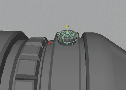
Create a cylinder and decrease its Subdivisions Caps to 0. Select the top cap face and, with a series of extrusions and bevels, create a pattern that you find interesting. Mine turned out like Figure 8.16.
Position the new cylinder along the left or right side ring near the base of the tapered sides. Position it so it is sticking up from the top of the canister like you see in Figure 8.17.
With the cylinder selected, press the Insert key to enter Edit Pivot mode. Hold the V key to enable Snap To Point and click and drag on the green y-axis handle, dragging it to a center point of the cylinder. The pivot should align to the center point of the canister.
Press Insert again to exit Edit Pivot mode. Duplicate the cylinder piece and rotate it about 30 degrees in either direction. Press Shift+D to Duplicate With Transform to create another cylinder 30 degrees from the prior one. Continue to press Shift+D until the cylinders are arrayed in a ring around the canister.
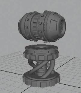
Duplicate these cylinders to place another ring on the opposite end of the canister. The final result should look something like Figure 8.18.

As with all current-generation game props, you'll need to create a low-resolution mesh to use for the actual game asset. The low-resolution mesh has all the high-resolution details baked into its texture to allow for the game's technology to sell the illusion of a higher-detail mesh than there actually is. For this prop, the main thing to keep in mind is that simpler is better. Not every indentation and groove needs to be represented by geometry. In most cases, such details can be covered through the use of normal maps and such. The windows cut into the caps of the canister, for example, could be represented through the normal map. The larger windows cut into the tapered surfaces on either side of the canister, however, are large enough details that representing them within the low-resolution geometry could be better.
It comes down to what your final asset's polycount budget affords you. If the asset needs to be down to, for example, less than a thousand polygons, you'd have to choose your details very carefully. In such cases, only the largest of details would be wanted in the mesh, while all other details would remain in the texture.
Note
Following the steps that have been gone over several times in this book, you can eventually come to the final low-resolution mesh shown in Figure 8.19. Don't forget that you can always check out the step-by-step explanation of how this particular mesh was created by watching the video supplement on the book's DVD.
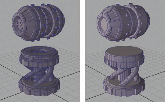
Once you have your low-resolution mesh completed, you can begin UV mapping it to prepare the mesh for texturing. The most important aspect of UV mapping is efficiency—efficiency of space, to be exact. You want to make every pixel of your texture count, with as little unused space as possible. You also want each piece of the model to be represented by a proportional amount of texture space (large objects get more UV space than small objects). With that in mind, take a look at your model and study it to see if there are any possibilities for mirroring your texture.
In other words, are there parts of the model that are identical and could share UV texture space? If there are, what I tend to do is to delete the duplicate sections of the model, UV map the remainder, and add back in the missing sides by duplicating the finished UV mapped portions.
For my model (which will be similar to yours if you are following along), I ended up with what you see in Figure 8.20. I deleted half of the pedestal rims, all but one of the small cylinder shapes and spiraling pedestal supports, and one end of the canister.

Select what is left of the canister and choose Create UVs → Cylindrical Mapping. You may need to rotate the mapping gizmo by clicking the small, red hash mark in one of its corners and clicking the blue rotation circle to enable the rotation controls. Adjust the cylindrical mapping gizmo until the UVs of the canister are laid out in a square in the UV Texture Editor (accessible from the Window menu).
Select the cap faces and choose Create UVs → Planar Mapping → Options. In the Planar Mapping options box that opens, change the Project From setting to the applicable axis direction you'll be projecting from. In my case, it's the x-axis. Click the Project button.
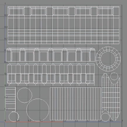
In the UV Editor, make any adjustments you may find necessary and lay out the UV shells as you see in Figure 8.21.
Continue to map and lay out the rest of the geometry in the same fashion. Apply cylindrical maps to the cylindrical shapes and planar maps to the caps and ends. Eventually, you should end up with something similar to Figure 8.22.
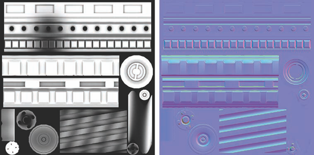
Now you can generate your ambient occlusion and normal map sources. Just as you've done in the other projects within this book, create an AO and a normal map using the Transfer Maps command (found in the Rendering menu set under Lighting/Shading → Transfer Maps). Mine turned out like Figure 8.23.
Once your textures are generated, you can duplicate the remaining halves of the mesh and use them to fill in the gaps. Since the meshes you are duplicating are already mapped with UVs, the duplicates will share those same UV coordinates. The result will look like Figure 8.24.


Now that the mesh is complete, you can focus on completing the prop's textures. For this prop, you'll need a diffuse map, a normal map, a specular map, and an emissive map for the glow effect.
The emissive map is rather quick, so you can tackle it first. Open your AO texture in Photoshop. Double-click the background layer and press OK to convert it to a normal layer. Rename it
AO.Create a new layer. Rename the new layer
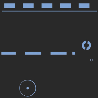
Glow.Using the details found in your AO layer as a guide, select the areas that you want to glow. In your glow layer, fill these areas with a light blue color.
Create a new layer and place it below the Glow layer. Fill it with black. The result (Figure 8.25) is your emissive texture. Save it as
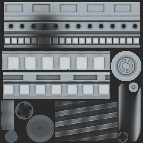
canister_emissive.tga(orcanister_glow.tga).To begin the diffuse texture, open a metal texture source that doesn't have too much variation or contrast, such as the aluminum texture source that comes with this book's DVD. Drag it into your Photoshop file and place its layer below the AO layer. Fill the layer with the metal source, either by resizing it or copying it across the full image.
Adjust your metal image's saturation and contrast to make it have a blue tint with very low contrast. If you are using the textures provided in this book, you'll want to apply a Hue/Saturation adjustment layer and click the Colorize option in the lower-right corner of the Hue/Saturation dialog box.
The Colorize setting will override the current hue values and apply a completely new hue value. Without Colorize checked, the hue adjustment is reliant on the image's original hue value. So, with Colorize checked, you can adjust the hue to be a blue color and lower the saturation down to around 12 or so to make the color more of a subtle tinting.
Note
If you need to, you can apply a Brightness/Contrast adjustment layer to further adjust the source metal image to your preference.
Create a new Brightness/Contrast adjustment layer and drag the Brightness slider way down to, for example, −90. Increase the Contrast slider slightly to be around 10.
Select the adjustment layer's mask (the white box next to its layer image within the Layer palette) and fill with black, removing the adjustment layer's affect from the image.
With the mask still selected in the Layer palette, take a soft white brush and paint in the shadows in the low parts of the image. These would be the undersides of surfaces as well as the grooves and indentations.
Once the shadows are painted as you like, create a Hue/Saturation adjustment layer and increase the Lightness value to around 35 or so. Fill its mask with black and, with a white brush, paint in the extruded areas to brighten them. These would be, for example, the gear-like teeth around the rims of the pedestal. You should have something like Figure 8.26.
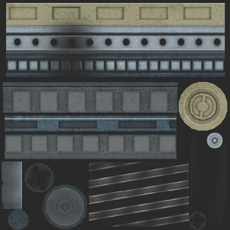
You can create additional Hue/Saturation adjustment layers and adjust the color values of the different sections of the prop to your liking. For example, I made the spiraling support bars a dark color and also darkened the pedestal overall so that the canister would stand out. In addition to making different areas brighter or darker, I also applied some color changes, making the ends of the canister a gold color.
To add more variation to certain elements of the prop, you can bring in other texture sources and blend them over the top of the existing metal. For example, you can bring in the Alumox metal source image from the DVD to apply a bit of surface variation. This texture source image has a splotchier metal look. Drag it into your Photoshop file and fill the image.
Adjust the layer's Blending Mode to Linear Light. This brightens the image and increases the contrast of the metal's splotches.
Apply a Hue/Saturation adjustment layer and decrease the Lightness value to darken the image, but maintain the contrast adjustment.
Although the contrast is pretty good, it's affecting the image more than I'd like. One way to have more control over the image blending is to adjust exactly how the images blend together.
Right-click the splotchy metal layer and from the menu that appears, choose Blending Options. The Layer Style dialog box will open. At the bottom you should see two sliders. These two sliders adjust the blending of either the currently selected layer or the blending between the current layer and the rest of the image beneath it.
Play with these two sliders until you get a look that you like. You can see how mine turned out in Figure 8.27.
Save this image as
Canister_Diffuse.tga.Lastly, you'll create the specular map. Hide the AO layers and the shadow and highlight adjustment layers, leaving only the surface details and colors. Press Ctrl+A to select the entire canvas. Press Ctrl+Shift+C to copy the visible image. Create a new layer and paste.
You don't necessarily want the glowing portions of the prop to be highly specular since it could destroy the illusion of light being emitted from within the device. Find your Glow layer and Ctrl-click its thumbnail in the Layer palette. This will load it as a selection. Back in your specular layer, fill the selection with black.
One thing I like to do is punch up the saturation of the specular and contrast of the specular map. You can do this with adjustment layers. Once you have a specular map you like (such as Figure 8.28) save it as
Canister_Specular.tga.

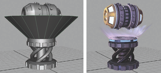
If you recall from our initial job specifications, your boss wanted the prop to glow. You created an emissive map to cause certain parts of the prop to emanate a glowing blue color, but you could add a new piece of geometry to sell the prop's hovering effect.
These kinds of geometry effects are old fashioned, but still used a lot with certain environmental effects. To create beams of light or even falling drops of water, an environment artist may create a geometric shape representing the effect with an animated opacity texture to create the effect's look. You'll do something similar here.
Open Photoshop and create a blank image that is 512×512 resolution.
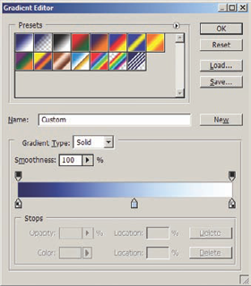
Select the Gradient Tool (G) and at the top-left of the interface and in the Options Bar, click the black-to-white gradient to access the Gradient Editor window.
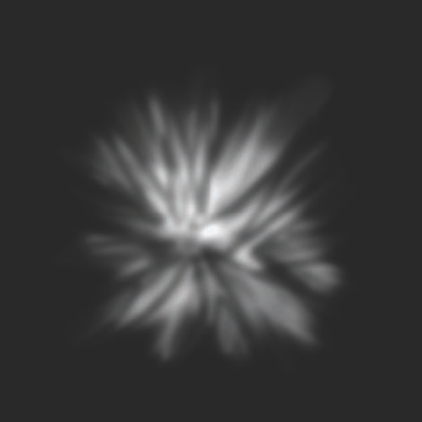
In the Gradient Editor, adjust the colors to be a blue-to-white gradient like in Figure 8.29.
Once you have a gradient that you like, click the OK button to exit the Gradient Editor.
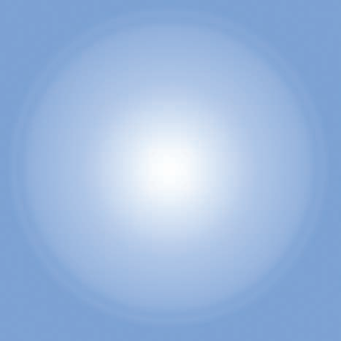
Back in the Options Bar, at the top of the interface, you'll see a series of buttons that change the type of gradient being used. Click the second one to toggle Radial Gradient. This will paint a gradient in a circular pattern with the colors blending from the center of the circle to the outer edge of the circle.
In your image, click in the approximate center (it doesn't have to be perfect) and drag out toward the side. This will paint in the circular gradient. The goal is to get a gradient that looks like Figure 8.30.
Note
If your gradient is backward from your desired result, check the Reverse option in the Options Bar and draw the gradient again.
Rename this layer
Color(you may need to double-click the layer to convert it from a background layer to a normal layer). Create a new layer and fill with black.Create a third layer above the black layer. Choose a white color and a soft brush and paint a radiant glow outward from the approximate center of the image. It does not need to be perfect or even all that pretty. Paint it so that you get a nice radial pattern of white that is similar to Figure 8.31.
Save the white on black image as
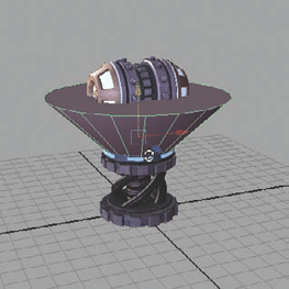
Light_Opacity.tga. Hide the top two layers and save the blue-to-white gradient image asLight_Diffuse.tga.Open your Maya canister scene. Create a polygonal cone primitive. Rotate it 90 degrees so that the point is pointing downward and reposition it on your model, as you see in Figure 8.32.
Select the cap face on the base of the cone and delete it. In the Front view, use the Cut Faces Tool (from the Edit Mesh menu) to cut a horizontal line across the cone where it meets the pedestal geometry. Delete the geometry below that line, leaving the remainder.
With the remaining cone geometry selected, select Create UVs → Planar Map → Options. In the options, choose the y-axis to project from and click the Project button.
Apply a new material to the cone geometry and apply the Light_Diffuse.tga image to its Color attribute. Apply the Light_Opacity.tga image to its Transparency and Incandescence attribute. You should get a result similar to Figure 8.33.
Feel free to add as many more glowing geometry shapes to your prop as you wish to get the look you desire.
MANUALLY CONNECTING OPACITY
If your cone geometry's opacity texture is not displaying correctly, you may need to manually connect it to the material's Transparency attribute. Do this by opening the Hypershade (Window → Rendering Editors → Hypershade).
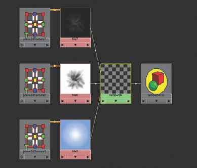
In the Hypershade, in the upper window, select the glow material that you applied to the cone. Click the Input And Output Connections button (indicated by a box with two arrows). You should see something like the below graphic:
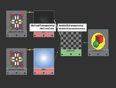
Hover your cursor over the connection between the Light_Opacity.tga and the material. You should see something like the above. What's happening is that the transparency of the opacity image is connected to the Transparency attribute of the material. What you actually want is for the color of the opacity image to be connected to the Transparency attribute of the material. You can fix this by following these steps.
Select the line connecting the
Light_Opacity.tgaimage to the material and delete it by pressing the Delete key.Middle-mouse click and drag the
Light_Opacity.tgaimage onto the material. A list will appear. Choose the bottom option: Other.The Connection Editor will open. On the left side are all of the attributes of your image file and on the right side are all of the attributes of the material. Clicking an attribute on the left and the right links those attributes together.
In the left column, find and select the outColor attribute. In the right column, find and select the Transparency attribute. This will link the two and make the Transparency attribute display accurately in your scene. Click Close.
However, you may notice that the transparency that is displayed is reversed from what you want! This can easily be fixed by double-clicking the image file node to open its attributes. Open the Effects section of the image's attributes and check the Invert checkbox. The transparency will display correctly.
Don't forget to apply a new copy of the
Light_Opacity.tgafile to the Incandescenceattribute!
You've essentially completed your prop at this point; however, one of the boss's stipulations at the beginning was that he wanted this thing to move. Since the canister is hovering above the glowing pedestal, you can focus on it.
First, make sure that your timeline is set correctly. Click the Animation Preferences button on the far right side of your Range Slider, below the playback controls.
Make sure your playback speed is set to 30 frames per second (fps). If your playback speed is set to 22 fps, you can change it under the Settings section of the Preferences window, in the Time setting.
Click Save and return to your scene.
Select the canister pieces and combine them together (Mesh → Combine). You can rename the combined objects
Canister.In the Time Slider, go to frame 1. Select the canister and press Shift+W and Shift+C. These are the keyboard shortcut commands for Key Transform and Key Rotation channels.
Go to frame 61. Rotate the canister 354 degrees in the y-axis and key the transform and rotation channels again.
Go to frame 30 and lower the canister slightly in the y-axis. Set a key for the transform channels.
Press the Play button. You should see the canister spin on its axis and subtly bob up and down in space. If you'd like to add movement to the glowing light cone, you can do so using the same methods.
After adding animation, you have completed your sci-fi prop to the "boss's" orders. Time for the next one!
I hope these projects have taught you how real game environments and props are created. The pipeline for asset creation is always in flux and advancing with new technology, and it's up to you to keep up. In the next chapter, you'll learn about some additional procedures and knowledge that an environment artist should be aware of before walking into a project.
