Vehicles can play a pivotal role in games. Racing games obviously make heavy use of them, such as the popular Gran Turismo series, which provides hundreds of cars to choose from! Other games may use vehicles as the player's primary mode of transportation within the game's world, such as in the aptly named Grand Theft Auto series. In general, even if it's not a racing game but features some form of civilization, you can bet vehicles will need to be made.
A game doesn't have to focus on driving to need vehicles. Even a game like Activision's GUN, set in the 1880s in America's Old West, had carriages and wagons populating the world. If a game features a city environment, even if the player never actually gets behind the wheel, you can bet there will be cars, trucks, and vans driving around or parked on the city streets. Even a one-on-one fighting game like Capcom's Street Fighter 4 has vehicles populating the backgrounds of a few of its stages.
When it comes to creating a vehicle, the overall techniques involved are essentially the same as those used when creating any other prop. But you'll want to ask yourself several questions before you start creating any vehicles.
First, can the player see inside the vehicle? Adding interiors to the dozens, if not hundreds, of cars and trucks populating your game world will increase the polycounts and texture usages considerably. Many games opt to tint all the vehicles' windows or simply make them all highly reflective to hide or obscure whatever may or may not be inside them. Knowing whether the interiors are necessary for your game is obviously very important. After all, if no one is going to see the insides, there's no need to make them!
Next, will the vehicle get damaged? In action games that feature vehicle-based combat especially, such as THQ's Saint's Row, it's very likely that when the bullets, grenades, and missiles start flying, the vehicles will get caught in the crossfire. If they show damage effects like crumpled bumpers, caved-in canopies, busted taillights, and so on, these kinds of damage models will need to be created based on the game's implementation of such effects.
Finally, will the player be able to modify or upgrade the vehicle in any way during the game? Racing games especially can feature intense car customization features. These can range from adding decals to your car's hood to replacing your engine and fine-tuning your suspension. Adding decals to certain parts may require certain specifications in the UV layout of the car model, and all of those different customizable parts will need some sort of art-related presentation, showing under-the-hood as well as under-the-frame views in many cases.
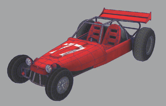
For the project in this chapter, you'll tackle a vehicle that's mildly complex; specifically, you'll create an extreme sports–style dune buggy! These durable vehicles can range greatly in style and shape, so search the Internet to find some image references for inspiration.
Note
Before starting, make sure you set your project to your project directory by going to File → Project → Set.
The first step is to create the basic roll cage that will make up the overall shape of the buggy's cockpit. You'll do this with a number of basic pipes arranged to create the shape and merged or fitted together where they meet.
Select Create → CV Curve Tool → Options. In the Tool Settings dialog box that opens, change the Curve Degree setting to 1 (Linear). This will cause the curve you lay out with the tool to be rigid rather than smooth. This will help you lay out the roll cage more precisely.
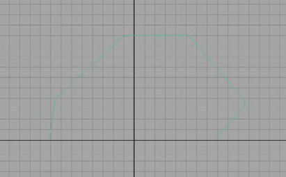
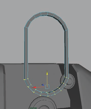
In the Side view, draw the shape of the cockpit roll cage however you desire, using reference or your own idea. You can use extra points on the corners to create a rounded shape. Mine looks like Figure 4.1.
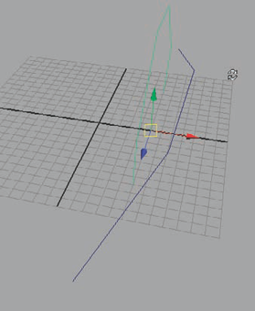
Switch to the Perspective view, and move the curve to the left or right of the origin, approximately 5 units or so, depending on how large you drew it.
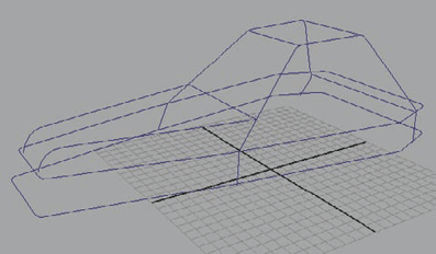
In the Top view, draw out a new curve, using four or five points, that fits around the cockpit roll cage curve and extends forward to the front end where the hood of the buggy will eventually be (Figure 4.2).
Select both curves and duplicate them (Ctrl+D). With the duplicate curves selected, group them (Ctrl+G). With the group selected, change the ScaleX attribute in the Channel Box to −1 to mirror the curves to the other side of the origin. Select Edit → Ungroup to remove them from the group.
Removing the curves from the group will keep your scene clear of miscellaneous group nodes, which can build up quickly if you do this method of mirroring often, as I sometimes do.
With the curves now mirrored, you can more clearly see what your overall shape is starting to look like and begin making adjustments with a fuller picture in mind. For example, I noticed that I had made the hood of the buggy much too narrow and therefore widened the curves accordingly.
Reshape the curves as you like, but be sure to grab the top of the roll cage (that makes up the roof of the cockpit) and move them in as in Figure 4.3.
In the Top view, draw out a straight curve using three points that joins the front corners of the cockpit roof. Repeat for the back corners. Switch to the Perspective view to position them at the top corners of the cockpit. Create two more lines for the base of the cockpit in the front and back. These will act as the roll cage's support bars.
Back in the Top view, hold the C key to toggle Snap To Curve mode. While still holding the button, left-click on the frame's left profile curve and drag to its front end. Release the left mouse button, and let go of the C key. Continue to draw out a curve, merging the left frame profile curve with the right. For the last point, hold the C key again to snap the last point to the front end of the right profile curve. You can see my result in Figure 4.4. If you like, you can use a few extra points to round the corners.
Return to the Perspective view, and make sure the curve is aligned with the frame's curves. Select the left frame curve, and Shift-select the front curve you just made. Change your menu set to Surfaces, and select Edit Curves → Attach Curves → Options. In the Options dialog box that opens, make sure the Keep Originals check box is unchecked and the Attach Method is set to Blend. Click the Attach button. This will merge your two selected curves together.
With your newly merged curve selected, Shift-select the other frame curve and attach them again. Delete the curve's history (Edit → Delete By Type → History).
Repeat steps 8–10 with the back end of the frame, creating a curve between the two ends of the back frame curve and merging the curves together. Since you'll be creating a closed (or periodic) curve with the second attachment, you'll instead need to use the Open/Close Curves command (found under the Edit Curves menu) to merge the last corner of the curve.
Adjust the curve's shape how you like. Duplicate it and lower it down to form the lower bar of the buggy's frame (Figure 4.5).
Switch to the Side view. Draw out a curve forming the top of the hood, curving it at the front to act as the lip of the hood.
Back in the Perspective view, reposition the hood curve so that its base is at the corner of the cockpit and the hood curve ends at the front corner of the buggy frame, as in Figure 4.6. Mirror the hood curve for the other side.
Position several small, straight curves around the frame, connecting the top and bottom frame curves together with what will become support bars. You can see in my example (Figure 4.7) that I put several in the front and back and added diagonal bars to the sides.
Now, you can start creating the actual pipe geometry. Select Create → NURBS Primitives → Circle and drag out a circle in your scene. This circle will represent the diameter of your pipes, so scale it accordingly to a thickness you like.
Select the circle and Shift-select one of your many curves. With them both selected, select Surfaces → Extrude.
Note
For your Surfaces → Extrude commands, make sure you go into the options and set the output geometry to Polygons. I'm using a General tessellation method with the Per Span # of Iso Params set to U—1 and V—2.
Take note of how thick the pipe is that resulted from your Extrude. If you want to change it, you can do so by simply scaling the circle. Since history is still active, your pipe will update in real time. Once you have a thickness you like, you can continue.
Next, begin extruding the rest of the curves by repeating step 17. Make certain that for each one, you first select the circle and then select the path curve for each pipe in turn. Don't forget that you can use the G shortcut key to redo the last command. You should eventually have something like Figure 4.8. Feel free to add more pipes to the frame to make whatever kind of support frame you want for your buggy!


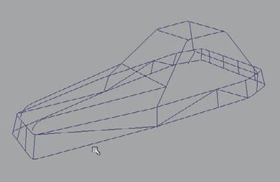

At this point, you can continue to create more pipes to shape the buggy's frame however you like. You also can change the shape and add more support structures to your liking. Once you have the frame the way you want, you can continue to the next section.
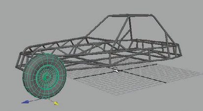
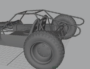
With the basic frame and shape of the buggy worked out, you can begin placing the wheels. For this project, I've chosen a more "off-road" style of dune buggy, with large, gripping rear wheels and smaller front wheels. This will require the roll cage to tilt downward from back to front. Before you know how much tilt it needs, however, you must first create the wheels with the following steps:
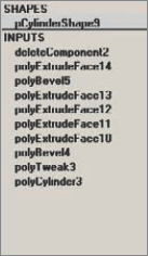
Hide your roll cage. You'll then start with a cylinder placed on its side. If you're following along with me, the cylinder should be scaled up about 1.5 units in the X and Z directions and .4 units in the Y, which creates a wheel shape, as in Figure 4.9.
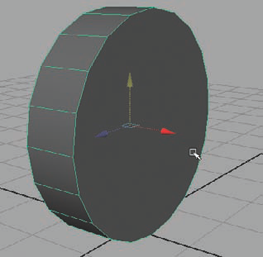
Select both round cap faces of the cylinder and bevel them to begin rounding the wheel. The next series of moves will be dependent on what you want the hubcap of the wheel to look like. After a series of beveling and extruding processes, my result ended up like Figure 4.10. (See the "Using Object History" sidebar for more information regarding using history.)
To achieve the opposite side of the wheel, you'll cut the wheel in half and duplicate the front of the wheel to the back. Using Edit Mesh → Insert Edge Loop tool, insert an edge loop down the middle of the wheel. You can grid-snap the resulting loop to make certain it is centered. Then delete the backside faces of the wheel.
USING OBJECT HISTORY
From the blank cylinder face to the hubcap detail you see in Figure 4.10, I used about a dozen or so Bevels and Extrudes. You may believe that exhaustive planning and knowing exactly what you are going to do is required before beginning, but that really isn't the case. It may seem daunting, but it really is quite easy to achieve such a result. First, I recommend having a good reference for the kind of hubcap detail you want to achieve. But otherwise, the trick is to make good use of your history.
Each time you use a Bevel or an Extrude (or almost any other command), it gets added to the object's history in the long list you see on the right side of the screen in the Channel Box. In this example, for instance, the list contains several Extrude commands and a couple of Bevels thrown in for good measure:
This list exists for more than simply telling you what you've already done. This list is a time machine! It allows you to go back in time to something you did several steps ago and make a change. That change then propagates forward in time to the present, changing every step you did in between to match the new change.
By simply clicking nearly any editable input in the Channel Box, you get access to the options of that input. You can also use the Show Manipulator tool (the Y shortcut key) to manipulate the past in your scene.
What does this mean for the buggy wheel? Well, if you've made several Extrudes and Bevels and then realize that six steps ago you really should have pushed that extrude a little further inward, you can! Remembering that you can access your history will help you with not only this project but hundreds more to come.
Duplicate the remaining half, scale it −1 in the mirroring direction (the x-axis in my case), and select Edit Mesh → Combine to combine the wheel halves together. Use the Edit Mesh → Merge command to weld the bordering vertices together.
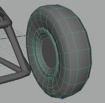
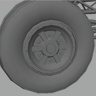
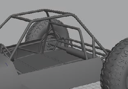
Unhide the roll cage mesh, and reposition and rescale your wheel in relation to the size and position of your buggy's frame. Mine looks like Figure 4.11.
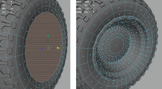
The hubcap detail that looks great for the front of the wheel is a bit too complex for the back of it. Select the faces that make up the middle detail of the hubcap and delete them. Then select Mesh → Fill Hole to cap it like in Figure 4.12.
Duplicate the front wheel, and move it to the back of the buggy. Resize the wheel as you see fit. In my case, I made the rear wheel about 50 percent larger overall and made the rubber part of the wheel thicker and wider.
You can create a different hubcap detail for the rear wheel if you want. I made the rear wheel hubcap a bit less complex, for instance.
After you've resized the rear wheel like you want, position it on the buggy. If yours is like mine, you'll need to angle the buggy's frame to match the elevations of the two wheels. Select all roll cage pipes and group them together (Ctrl+G). With the new group selected, reposition the roll cage to match the new wheel positions.
This can be made easier by repositioning the group's pivot point at the front or back wheel position. Then you simply rotate the group to adjust the elevation.
The next step is to create the tread detail. For this project, the rear wheel will have the heavy-duty tread detail, while the front wheel has less extreme tread detail.
Working around the axis will make the next steps easier, because it will require a lot of precise rotations. However, you don't want to lose your wheel position, especially if you have it dialed in perfectly and don't want to fight to find it again. You'll get around that by creating a surrogate. Duplicate the rear wheel, center the pivot (Edit → Center Pivot), and grid-snap it to the origin. You can hide the rest of the buggy.
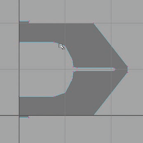
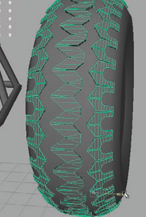
In the Top view, select Mesh → Create Polygon Tool, and create a shape that will form a pattern on your tire's tread. I used a pattern similar to one I found in reference photos online, which looks like Figure 4.13.
Move the tread detail to the top of the wheel's rubber surface and extrude it upward, giving it thickness. Delete the two faces on the ends where the pattern would meet.
The next step will require a bit of experimentation on your part, because the exact values involved depend on how big your tread detail and wheel diameter are.
With your tread detail selected, press the Insert key on the keyboard to enter Edit Pivot mode. Point-snap the pivot point to the center of the wheel. Press Insert again to exit Edit Pivot mode.
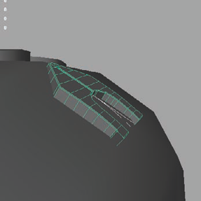
Duplicate the tread piece. Now, in my case, rotating the tread 10 degrees in the x-axis rotated the duplicate tread enough to butt up next to the original. Pressing Shift+D at this point will invoke the Duplicate With Transform command, creating additional duplicates that each rotate an additional 10 degrees around the wheel, meeting on the other end (Figure 4.14).
If your geometry doesn't meet up perfectly at the end of the circle, undo the duplicates, and try again with a different rotation value until you get it just right.
This part can be pretty tedious. Select all of your tread pieces, and combine (Mesh → Combine) them together. Next, go through and merge the pieces' vertices together using the command found under Edit Mesh → Merge. Eventually, you'll have them all merged together and ready to go!
Repeat the process with a new tread pattern that complements the first. I went with a shape that you see in Figure 4.15.
For this detail to go on the rounded edge of the tire, you'll need to cut in some bendable geometry that you can then adjust to follow the surface direction of the tire (Figure 4.16). You can do this by hand or by using a Bend deformer that can be found in the Animation menu set under Create Deformers → Nonlinear → Bend.
Once the tread detail is curved, you can then duplicate it around the wheel in the same way you did before, merging the resulting segments together to form one piece. For this curving edge piece, duplicate it and mirror it to the other side of the wheel to curve along the opposite edge.
Once you have all the tread detail you want, position it on the wheel the way you like it. I placed my first tread along the middle of the wheel with the edge tread on either side, positioned so that the pointed ends fit into the concave ends of the adjacent pieces (as shown in Figure 4.17).
You can continue creating all the tread detail you want. Once you're done, you'll then need to transplant this tread detail onto your original rear wheel and delete the surrogate.
Select all the tread detail and group or combine it together. Center the pivot and unhide your hidden buggy parts. Delete the surrogate rear wheel. Point-snap align your new tread detail onto the real rear wheel.
Note
The Align tool can assist you in aligning objects together. First, select the object that will move and then Shift-select the object you'll be aligning to. Then select Modify → Align Tool and select the corresponding indicator on the gizmo that represents the point on the object you wish to align to.
For the front wheel, you can create whatever kind of tread detail you like. For my own, I used the Extrude tool and a couple of Bevels to create a few raised ridges along the circumference of the wheel—a large, thick ridge in the center and two small, thin ridges on either rounded edge (Figure 4.18).
Create a small cylinder. This will be a bolt for the front wheel's hubcap. Depending on the hubcap design you've chosen, position however many duplicate bolts on the hubcap to add detail to the wheel. In my case, I placed them around the outer rim of the hubcap as well as around the inner area, around the center of the hubcap.
If you are following along with me, you can also add some details to the hubcap, such as some support struts. In the Side view, drag out a tall cube, with its Subdivisions Width set to 5, which gives it several divisions along its vertical length. Bevel the forward-facing edges and position it on the wheel. You can adjust the vertices to make the shape of the strut curve outward from the center of the wheel and duplicate them around the hubcap's center as in Figure 4.19.
As with the front wheel back in step 2, you can do the same with the rear wheel in creating hubcap detail. Using a series of Extrudes and Bevels, manipulating the history to manipulate the shape, I got something like Figure 4.20. You can detail your own in any way you like!
As with the front wheel, you can also place bolts on the hubcap to add detail in any way you see fit.
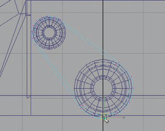
Now that you have the two wheels created, you can begin attaching them to the frame. In the Top view, use the CV Curve tool to draw a curve from the front corner of the roll cage to the wheel. When the curve meets the wheel, draw a point above (from your vantage point in the Top view) the last, making the curve angle abruptly toward the rear of the wheel. Be sure to position the curve on the wheel with its base touching the frame and its curved end placed flush against the upper part of the wheel's inner hubcap. You may need to adjust its control vertices to make the curve fit correctly (Figure 4.21).
Once you have the curve positioned, duplicate it and lower it to the lower side of the wheel with its base connected to the lower corner of the roll cage framework. Rotate the curve upward slightly if needed and adjust the control vertices to fit the new position.
Using the Surfaces → Extrude command from the Surfaces menu set, create two new frame pipes with these two curves. Because the ends of these two pipes are exposed (and not buried into another pipe like most of the others), you can cap them with the Mesh → Fill Hole command and add a slight bevel if desired.
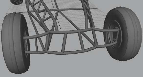
You can then add two straight support pipes joining the two together. Once you're done with that, you can select all the wheel parts as well as the connector frame that you just made, duplicate them, group them, and mirror them over to the other side (Figure 4.22).
Repeat this process for the rear wheels, connecting them to the frame as well.


Most of these heavy-duty dune buggies have some equally heavy-duty shock absorber coils connected to the wheels. Some have them on both the front and rear wheels, but for this project they'll just be on the front. However, if you'd like to add them to the rear of your buggy as well, you're more than welcome to do so!
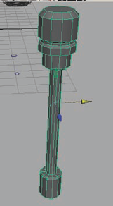
Create a tall thin cylinder, and decrease its Subdivisions Axis to 12. Select the face on the top and then the bottom of the cylinder, and use a series of extrusions and Bevels to get a result similar to Figure 4.23. This will be the shock absorber frame that will attach the roll cage and wheel together.
For the coiled spring of the shock absorber, you will create a helix primitive object. It can be found under Create → Polygonal Primitives → Helix. The settings for this coil will depend a lot on just how large your shock absorber frame is; in my case I used these options:
Coils:
13
Height:
3.35
Width:
0.7
Radius:
0.05
Subdivisions Axis:
8
Subdivisions Coil:
12
Subdivisions Caps:
0
Position the spring to be centered on the shock absorber frame. You can adjust the coil to match your own frame if my settings didn't work for you.
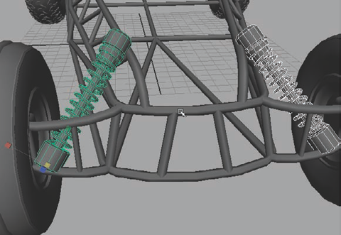
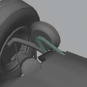
Select the coil and the frame and group them together. Reposition them to join the frame and wheel together at an angle like you see in Figure 4.24. Duplicate and mirror the shock absorber to the other side.
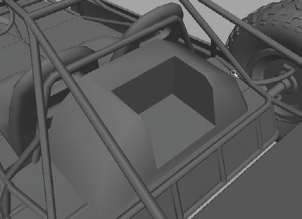
The next step will focus on the hood of the buggy. Not all dune buggies have coverings, but for this project, the idea is to create a racing buggy, with decals and such.
Create a U-shaped curve and place it over the front of the car, near the cockpit. Duplicate it and position it near the front end of the buggy between the front wheels. Select Surfaces → Loft (from the Surfaces menu set) to create a surface between the two curves as in Figure 4.25. Don't worry about clipping through the shock absorbers or anything at this point. You'll make space for them in a later step.
You can bevel the sides to soften them and curve them more around the hood.
Insert an edge loop down the center of the hood and delete the left side. You will later duplicate the completed half of the hood for the other side. Select the edges along the bottom side, behind the front wheels, and extrude them downward to cover the exposed roll cage framework.
Insert an edge near the cockpit, and lift up on the border edges to create a lip like in Figure 4.26.
With the Split Polygon tool (from the Edit Mesh menu), cut a shape out of the hood mesh that you'd like your hood to be, and delete the excess faces. I made a cut along the side of the hood that curved upward toward the front of the buggy. Then, I cut out a divot in the hood that the shock absorber could stick through. You can see my results in Figure 4.27, but you can shape yours however you like.
Select the two edges on the forward end, and lower them down to follow the downward curvature of the roll cage frame beneath it. Extrude the edge a few times, each time repositioning the extruded edge to follow the hood's curvature until you get about even with the wheel's connecting frame.
Select the edges on the outer edge of the newest faces and extrude them a couple of times outward to the sides, pulling them in to follow the curvature of the hood. Examine Figure 4.28 to see what I mean.
Next, use the Append To Polygon tool from the Edit Mesh menu to fill in the gap between the hood and these two extension pieces. Again, don't worry about clipping through the shocks.
You can use the Split Polygon tool again to cut the necessary hole for the shock absorbers into the hood.
Continue to modify the shape however you like, adjusting the curvature and the profile of the hood. When you're done, you can duplicate and mirror it to the other side.
Extrude the entire hood by a very small amount. I used an amount of about 0.02 units.
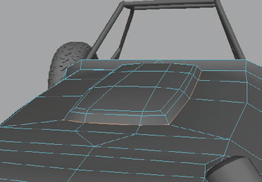
You can continue creating any additional hood details you want. I added a molded form to the hood by selecting the faces on top of the hood, extruding them up a few inches, and scaling them inward. I then beveled the center and border edges to round it out like in Figure 4.29.


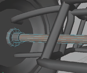
The rear wheels will not be pivoting to the left and right for steering, so for the next few steps, you'll create the rear wheel axle that would connect to a drive shaft that causes the wheels to spin, pushing the buggy along. You don't have to be too detailed for this particular project. The important thing you need is the axle because it will be the main part of the rear wheel drive that will be visible.
Create a cylinder and position it between the two rear wheels, aligned to the wheels' center point and centered on the buggy.
Select both end cap faces and extrude them outward a couple of times, with perhaps a Bevel or two thrown in for good measure, to create something like Figure 4.30.
If you like, you can thicken the center of the axle to give it some heft.
The next step is the steering wheel. As you may expect, it starts with a ring—a torus, to be exact.
Select Create → Polygon Primitives → Torus. Depending on your scene, your adjustments may vary from mine, which are as follows:
Radius:
1.5
Section Radius:
0.2
Subdivisions Axis:
40
Subdivisions Height:
8
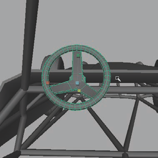
Next, you'll add the support struts to the steering wheel. Create a thin cube with a Subdivisions Height value of 2, splitting it in two sections. Lower the center edges down to cut the cube by a third and scale the opposite end inward, thereby tapering the width.
Move the tapered end toward the front, creating a leaning L shape. Bevel the long edges to smooth them a bit.
Position the shape on the steering wheel so that the tapered end meets the top of the wheel. You should get something like Figure 4.31.
If it's not already aligned, move the strut's pivot point to align with the center point of the steering wheel torus. Duplicate and rotate a new strut 120 degrees in the z-axis. Do it again for a third one. You should have three steering wheel struts placed equidistantly.
You'll probably notice that they all intersect at their base. Go ahead and create a small beveled cube to hide their intersection at their base. Once you have all the details you like, group them all together (Ctrl+G), reposition, and rescale the group to fit the buggy (Figure 4.32).

You have a hood covering the front of the buggy's frame, but the sides are still exposed. The next stage will focus on creating a side panel to cover the exposed framework on the sides of the buggy.
In the Top view, use the CV Curve tool to draw a path along the side of the buggy. Select the Perspective view, and reposition the curve to fit the side of the buggy side frame at its base.
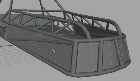
Duplicate the curve and move it up to the top of the buggy's side frame. Loft (Surfaces → Loft) the two curves, creating a surface in between (Figure 4.33). Don't worry if it's clipping through the frame; you're about to fix that.
If the Loft command didn't result in having an edge cutting through the middle of the panel horizontally (as in the prior Figure 4.33), use the Cut Faces tool from the Edit Mesh menu to make one.
Raise this center line up and outward, creating a slightly curved lip at the top of the paneling.
Select the entire panel and extrude it approximately 0.1 units to give the paneling some thickness. If it's still visibly clipping through the frame, you can reposition it.
The idea is to make the panel look as if it is below the hood. Grab the side faces that are facing the hood and extrude them forward. Reposition them to be beneath the hood and flush with the buggy's frame.
Grab the bottom forward-facing edge and bevel it. You should have something similar to Figure 4.34.
Continue to adjust the side panel however you like, adding any details you wish to see. For example, I beveled the outer edges slightly, giving the entire panel a more rounded appearance.


This would be a good time to create a new layer for your buggy so you can easily hide all the geometry you've created so far when your scene starts getting complex. Create a layer called HiRes, and add the current geometry to it. You'll notice that there's an obvious lack of floor to the buggy. Before you get started on it, ask yourself—how will the underside of the buggy be seen? Some games will allow you to focus on the underside quite closely. If that is the case, many details may need to be made. If it's not going to be seen at all, you don't need to spend as much time creating detail.
In the Top view, use the Create Polygon tool under the Mesh menu to draw an outline of the underside of the buggy.
Return to the Perspective view and reposition the mesh to align with the base of the frame.
This is about all you need to do for now. You'll return to the undercarriage later. However, if you'd like to add more details to the undercarriage, you can.
In this section, you'll create the all-important chair that the player could potentially sit in. You can do this in any number of ways and with different methods, but you'll try something a little different here: You'll try using curves, rather than starting with a cube or something (which is also a viable method). Using curves to build a profile of the chair allows you a better chance at previewing the profile of the mesh and getting that part right before filling it in with the rest of the details that follow.
First, you'll add to the roll cage by attaching a bar that will serve as a chair brace. In the Front view, draw an upside-down U-shaped curve from the left side to the right that will sit behind the chairs.
As with the prior roll cage pipes, use the Surfaces → Extrude command along with the profile circle created previously to extend a pipe along the curve's path. Set the pipe in place as if it were behind the (soon-to-be-made) chairs, like in Figure 4.35.
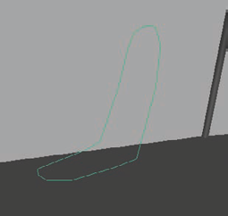
Back in the Front view, draw another upside-down U-shaped curve that will act as the profile of the back of the chair.
Duplicate the curve and rotate it 90 degrees to form the shape of the chair's seat, making sure both curves' end points are touching.
Modify the curve's vertices to curve the chair's form to fit the shape of a normal chair, like in Figure 4.36.
Select both curves and, under the Surfaces menu set, select Edit Curves → Attach Curves to connect the two curves together. However, this will attach the two only on one end.
To connect the other end as well, select Edit Curves → Open/Close Curve.
Note
Using the Open/Close Curve command could noticeably modify your curve's overall shape. If this happens, you can just edit the curve back to where you want it.
Once you have this curve shaped the way you want, select it and select Edit Curves → Offset → Offset Curve. Adjust the Distance value to be about −0.25.
In the Side view, adjust the control vertices of the new curve to make the distance between curves about equal all along the curve's path (Figure 4.37).
The plan is to loft a surface between these two curves; however, if your curves are anything like mine, doing so will result in a surface similar to this:

The geometry twisting that you see here is definitely not ideal. To fix this, you'll need to use the Rebuild Curve command.
Select one of the curves and press Ctrl+A to bring up the Attribute Editor. Make note of what the spans number is. In my case, the spans count was 16. Whatever span count you have is the number you'll want to use in the next step.
Select both curves, and select Edit Curves → Rebuild Curves → Options. In the options, make the following changes:
Parameter Range:
0 to #Spans
Number of Spans:
Your number (mine is 16)
Degree:
1 Linear
Click Apply. This makes the two curves match in their makeup and provides a much cleaner result when you apply the Loft in the next step.
With both curves still selected, select Surfaces → Loft. As you can see, this time, the surface is much cleaner (Figure 4.38).
Select the central edge loop using the Select Edge Loop tool (from the Select menu) and press Ctrl+F9. This shortcut command will convert your selection from edges to vertices. Double-click the Move tool to open the Tool Settings dialog box and change your Move Axis to Normal mode. Drag the N labeled directional handle on your move gizmo and pull out the row of vertices to add a slight curve to the shape of the lofted surface.
Use the Append To Polygon tool to fill in the front-facing center gap of the chair.
Select the gap faces and apply an Extrude, scaling the extrusion inward to create a curved indention to form the bucket seat of the chair, like in Figure 4.39.
Use the Append To Polygon tool to fill in the gap in the back of the chair. Reposition the chair to fit the buggy's cockpit and scale and tweak the geometry to your liking, if it isn't already. If you'd like to add a fluted appearance, you can use Booleans to cut out holes or add divots.


For this project, you'll create some globe-style headlights attached to the hood of the buggy. The idea is that the headlights were tacked on after the initial construction as a way of customization.
Create a sphere and decrease the Subdivisions Height to 12. Rotate it 90 degrees so that the poles are facing left to right and delete the back half's faces.
Scale in the remaining half to flatten the protrusion and make it not quite so extended outward. Use Mesh → Fill Hole to cap the backside.
Select the back face and use the Grow Selection Region command from the Select menu to grow the selection to include the next ring of faces. Extrude these outward to give the headlight a thicker frame border.
Again, select the back face and apply an extrude command. Scale it in about a quarter of the thickness of the back face. Apply a second Extrude and pull it out to give it some thickness. You should have something similar to Figure 4.40 when you're done.
Position the headlight on the front end of the hood on either the left or right side. In the Front view, draw a rounded, upside-down, V-shaped curve to serve as a support anchor for the headlight. After extruding a pipe along it, you should have something like Figure 4.41.
Duplicate and mirror the headlight and anchor frame to the other side.

As an optional part, you can add a rear spoiler onto the buggy. A spoiler is usually added for the purposes of aerodynamics and improving handling at high speeds. It also just looks cool!
First you'll create an addition to the buggy frame to put the spoiler on. In the Side view, create a rounded, V-shaped curve that extends from the top rear of the cockpit, out beyond the rear wheel, and then curves downward back to the top of the base frame.
As with the rest of the frame pieces, extrude a pipe through the path you made, and adjust the shape as you see fit.
Position the pipe to be on one side of the buggy, duplicate it, and mirror it over to the other side. You should have something like Figure 4.42.
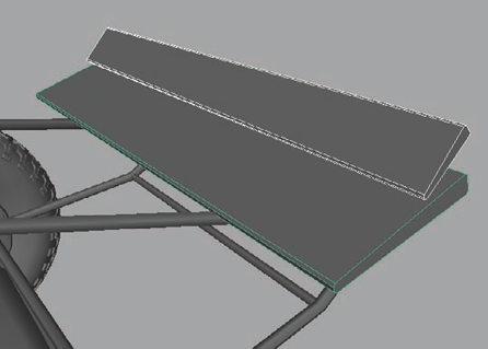
Create a long, thin cube and position it on the end of this new frame extension. Increase the width of the cube to be about even with the rear wheels.
Taper the end of the cube facing the front and widen the rear end, beveling the corners to round them. Make sure the cube is set on the frame properly.
Duplicate it and raise it up to create a second tier to the spoiler. Grab the front end vertices and push them back, shortening the second tier of the spoiler and angling it down to create an angle of approximately 30 degrees, like in Figure 4.43.
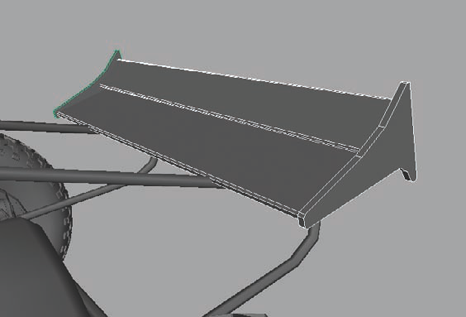
In the Side view, use the Create Polygon tool from the Mesh menu to create a shape that would act as a frame to hold the two spoiler blades. You can create any kind of shape, as long as it holds both spoiler blades. The one I made looks kind of like the state of Delaware or something, but that's OK, I guess!
Extrude the polygonal shape you create about two inches or so to give it some thickness and place it on the far end of the spoiler blades. Duplicate it and move it over to the opposite side. You should get something similar to Figure 4.44.
Next, you can create additional frame support by adding more pipes to the frame to reinforce the spoiler if it looks like it needs it.
Note
Keen-eyed readers will notice that the dune buggy's support strut was featured in Figure 4.43 but not in Figure 4.44. This is just a result of how I captured the images for this book and not me removing it. It's still there, just not shown, in Figure 4.44.
The engine for most dune buggies is located in the back of the buggy, so it depends on what kind of game you're working on to determine how detailed your engine should really be. You can truly be as detailed as you want for this project. For the purposes of this lesson, I'll demonstrate the creation of an engine of medium-level detail. I'll allow you to fill in any additional details you'd like on your own. Or if you prefer, you can simply follow along with me.
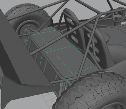
First, you'll need to create a platform for the engine to rest on. The way you can do this is by adding onto the base undercarriage mesh you made earlier. Select the edges around the back of the buggy, and extrude them up to fill in the area of the frame that surrounds the axle.
Extrude again and pull the edges forward to fill in the gap behind the chairs, then again to close off the gap, similar to what's shown in Figure 4.45.
Create a cube and place it on the platform. This will act as an engine cover that the engine will be placed inside. Taper the top of the cube and scale it to fit. Add a bevel to the front to create a lip to the engine cover shell.
Create another cube, insert it into the engine cover, and use a Difference Boolean to carve out (Mesh → Booleans → Difference) an opening in the cover in which to place the engine (Figure 4.46).
Create a cylinder and rotate it to face the back of the buggy. Position it in the front area of the engine cover's opening. You can extrude it a few times to give it some additional details and grooves if you like.
Duplicate it and scale it in the three axes so that it has a smaller diameter, but a similar thickness as the first. Mine was scaled 0.6 in the x- and z-axes and 0.3 in the y-axis, and it worked well. Place this smaller cylinder above and to the right of the original.
Create a torus and rotate it so that it faces the back of the buggy. This will act as a gear belt for the two gear cylinders you just made. Lower the Subdivisions Height to 4, and increase the Twist to 45.
Select the edge loops on the left middle and right middle of the torus and use the Edit Mesh → Delete command to remove them. This will change the torus from a circular shape to more of a pill shape.
Grab the lower half of the vertices and lower them down, stretching the shape like in Figure 4.47.
In the Front view, reposition the belt geometry to wrap around the two gear cylinders like in Figure 4.48.
Create a cube and place it within the engine cover, setting it on the base of the opening behind the gears. Bevel the topside edges to taper the shape. This will serve as the engine block.
Keep in mind that the engine of the buggy in this lesson will not be focused on very closely during play, so the details are rather minimal. If you'd like to go nuts and model a highly accurate engine block, please do!
Note
Continue to model the engine to the level of detail that you prefer. I added a few more basic engine parts simply to identify the engine as an engine. You can see how mine turned out in Figure 4.49. These engine parts were all created using simple cylinders and Extrudes and Bevels. If you need some more step-by-step instruction for this part, feel free to check out the video supplement on the DVD.
Next, you'll add some detail to the engine cover. Some simple Extrudes and Bevels can easily give you a metal paneling look. Create a small cylinder and place it on the cover to look like a bolt. Duplicate it however many times you feel necessary and place the bolts along the panel borders (Figure 4.50).


At this point, the high-resolution model is nearly complete. Continue to fill in any additional details that you want to add to this project to make it your own. The last bit that I added was a front grill to fill the gap in the frame.
Select the front edges of the undercarriage mesh that runs along the front and sides of the hood.
Extrude them upward, filling in the gap.
Adjust the vertices to line up with the shape of the frame, like in Figure 4.51.
Just as you did in Chapter 3, you'll now create the low-resolution mesh for the buggy that you'll burn your normal and AO maps to. The process for doing so is the same as with the revolver in the previous chapter. I'll reiterate the steps that you'll want to follow:
Assign all the current buggy meshes to the HiRes layer.
Create a new layer called
GameRes.Assign a new Lambert material to the high-resolution mesh and lower the color value to make it darker.
Duplicate the original high-resolution mesh.
Apply the Lambert1 material to the duplicate.
Select all of the duplicate mesh's vertices.
Using the Normal setting on the Move tool's Move Axis, push the duplicate geometry out so that it completely encompasses the original buggy's geometry.
Remove small geometric details that can be handled by the normal map once you create them later. I'll go over some of these instances next.
Remove any geometry that is obscured by other geometry and hidden from view.
Add the low-resolution object to the GameRes layer.
Return to step 4 and repeat for each mesh.
Note
You can watch a step-by-step video of each low-resolution mesh being created on the DVD that is included with this book.
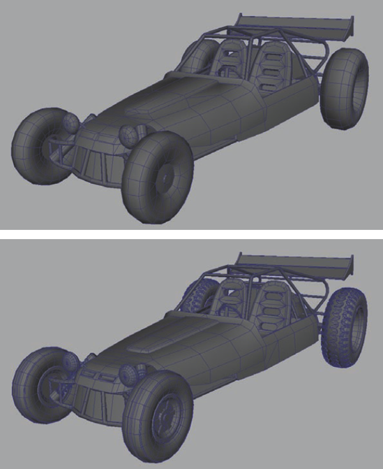
In Figure 4.52, you can see the difference between the high-resolution and low-resolution dune buggies.
UV mapping the buggy will be just like UV mapping the revolver from the prior chapter. Take each piece and focus on it individually. Be patient, as all of those pipes in the roll cage will take a while, but the end result will be worth it.
One thing you'll do differently with the buggy is UV map it with the intention of creating two textures—one for the frame and one for the rest. The reason for this is twofold. First of all, the pipe-based frame has so many pieces that it will take a significant amount of UV space to accommodate them all. Therefore, giving them their own texture allows you to give the rest of the buggy the amount of space its pieces require.
The other reason is that having a separate frame texture allows you to create multiple dune buggy variations using the same frame. Since the frame has its own texture, you can completely re-do the rest of the accompaniments to redesign a new buggy and not have to duplicate the texture for the frame itself.
Start first with the hood. Select the low-resolution hood mesh and apply an Automatic Mapping command from the Create UVs menu. You should get a result similar to Figure 4.53.
Obviously, this result is not satisfactory, so it will require some editing. The goal is to end up with two UV shells—one for the top of the hood and one for the bottom.
Focus first on the top of the hood, as that's the main part that people will naturally see. Select the largest UV shells (most likely the middle of the top and bottom of the hood) and move them to the side. For the remaining small parts, enter Edge component mode and select all the edges. Press the Cut UV Edges button (on the UV Editor toolbar or under Polygons → Cut UV Edges) to separate each selected face.
Select the left and right edges of the large UV Shell of the top of the hood and use the Move And Sew UV Edges command to attach the side faces to the side of the shell.
Because each face was separated from the small UV shells before, each face that you just connected is separate from each other face. The easiest way to attach them together is to select all the edges of the hood UV shell and then deselect all the highlighted edges that are separate from the UV shell. This will result in only the wanted edges being selected. Use the Sew UV Edges command to merge them together.
Continue to sew edges together, attaching UV shells to either the top or bottom UV section until you have both the top and bottom UV shells complete. If you accidentally attach a bottom section to the top UV shell, you can simply select the edges that attach them, cut them, and sew them where they belong. You should eventually get a result similar to Figure 4.54.

The reason the bottom of the hood is so much smaller than the top in this example is because the scale of the UV shells needs to be relative to each piece as well as dependent on their visibility. While the bottom of the hood is obviously the same size as the top, because it isn't really seen, the shell can be scaled much, much smaller.
Continue to UV map the rest of the buggy in the same way, skipping the frame for now. When you're done, it'll be time to arrange each UV shell into a workable texture sheet. In Figure 4.55, you can see how I arranged mine.

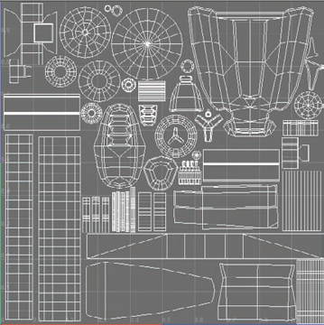
Notice that the pieces are, for the most part, correctly scaled in relation to each other. The hood, wheels, and chairs are the largest portions of the UV shell because they are the largest portions of the buggy. The major exception is the undercarriage, but since the undercarriage shouldn't be seen all that often, the scale doesn't have to be one-to-one with the rest of the vehicle.
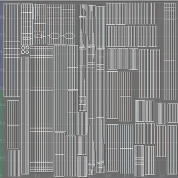
For the frame's UVs, you'll be following the same steps and arranging the UVs for their own frame texture. Be sure to lay out the UVs so that the longest pipes are the longest UV shells and so on. You can see how mine turned out in Figure 4.56.
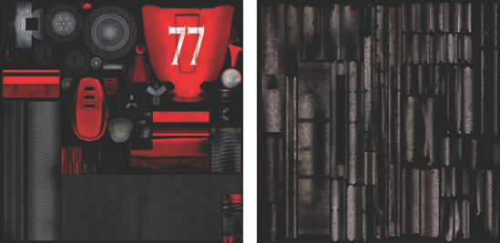
Once the UVs have been completed, you are able to bake normal and AO source textures for both the frame and the buggy. As you did in the prior chapters, you'll bake 1024×1024 resolution textures for the maps.
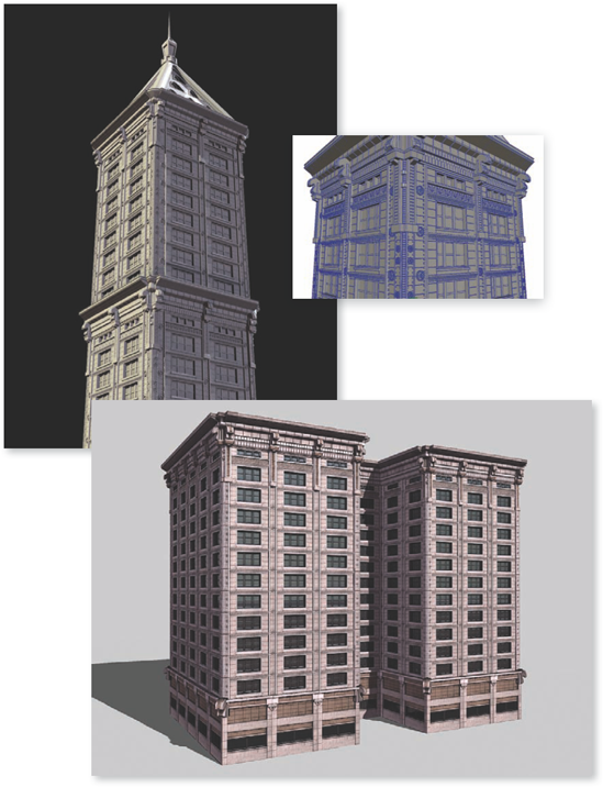
Aside from character work, a vehicle is arguably one of the more complex kinds of props you can create. Sometimes vehicles are simply props for the background. Other times, they are the focus of the entire game. In the next chapter, you'll tackle the challenge of creating the most common type of prop for an environment artist—a building!