
Although not in every game, combat appears in a large percentage of games. Whether it is guns, swords, or lightsabers, in combat-heavy games weapons play a major role. Especially in a game that requires switching weapons frequently, you may need to create a large variety of weapons. In fact, some role-playing games have arsenals of hundreds of unique weapon art assets for players to draw from. In this chapter, you'll focus on modeling in greater depth by going over some of the common modeling tools and commands that every game artist should know.
Weapons in video games can come in all sorts of themes. In Microsoft's Halo series, the weapons are science-fictional and alien, firing lasers, plasma bolts, and other sorts of fantastical, otherworldly ammunition. In Rockstar's Grand Theft Auto series, the weapons are more realistic—machine guns, rifles, grenades, missile launchers, and so on. Medieval themes also are commonly used in role-playing games like Square Enix's Final Fantasy series, in which swords, magic staves, and crossbows are the norm.
All that is to say that a weapon can look like nearly anything and can be almost anything. Even a baseball bat with some nails driven into it can be a powerful weapon, such as in Konami's SAW video game based on the popular horror movie franchise.
Depending on the type of game you work on, weapons may need to be created in multiple levels of detail. For instance, in a first-person shooter, the weapon the player wields is seen extremely close-up. Being able to scrutinize the model so closely means it needs to be highly detailed and polished. After all, players will always develop favorite weapons that they will literally see all the time, and you want those weapons to look good. On the other hand, the weapon that the player finds in the world (whether set on the floor, hanging from the wall, hidden in a treasure chest, or so forth) will be seen from a farther vantage point. Because that version of the weapon is seen from a relative distance, it can be far less detailed.
Some melee-type weapons require damage systems. In SAW, the melee weapons the player finds will become damaged as they are used until they break. Each different state of damage the weapon has is a separate model that needs to be created and swapped in by the programmers.
For this project, you'll be going to the Old West and creating an old-fashioned revolver. Creating such a weapon will bring you to a new level of complexity that I've yet to cover—animation. By animating the revolver, you can create several different animation sequences that a game can use during the course of play. Firing, reloading, jamming, and so on, all require that different parts of the weapon move. Such techniques would be used for any weapon that was composed of moving parts, from guns to chainsaws. You'll explore how in this chapter.
Note
Before you can jump straight into animation, you of course must first focus on creating the art for the weapon. You can probably find a ton of references online, but I've gone ahead and done the dirty work for you. On the DVD, open the pistol_start.ma file from the Chapter 3 project directory to begin. You'll first create a high-resolution mesh that you will use to bake your source textures from, as you have done in the previous chapters.
Note
Before starting, make sure you set your project to your project directory by going to File → Project → Set.
In the scene, I have a reference image already set up and in its own Reference layer. To create the revolver's cylinder, the aptly named rotating cylindrical casing that holds the weapon's bullets, select Create → Polygon Primitives → Cylinder and draw the shape of a simple cylinder.
Rotate it 90 degrees on the z-axis to flip the cylinder to lie horizontally.
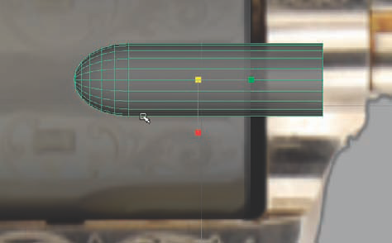
Change to the Front view and position scale and position the geometry to line up with the cylinder in the reference image like in Figure 3.1.
To make using the reference image easier, you can adjust the geometry's transparency. You could do this by turning on XRay mode in our viewport, but this makes everything transparent, reference image included. What you want is to make only your geometry transparent while maintaining the opaqueness of the reference image.
To do this, you can simply apply a new Lambert material onto it and adjust the material's Transparency slider up a tad. Now, your reference image maintains its opaqueness and you can see it through the geometry you're working with. Do this now to the cylinder to see whether it helps you when placing it. As you need to throughout this lesson, raise and lower the transparency of this material to help you match the reference image.
Once you have the cylinder's scale and position like you want it, return to the Perspective view and, under the polyCylinder1 Inputs in the Channel Box, reduce the Subdivisions Caps value to 0 and increase the Subdivisions Axis value to 40. This will make the cylinder much rounder, giving you a far smoother shape to work with.
Select both caps of the cylinder and apply a Bevel (Edit Mesh → Bevel). In the polyBevel1 Inputs in the Channel Box, you can adjust its Offset value from its default 0.5 (which is way too large) to something more like 0.05 to give it a nice beveled edge.
Now, create a polygon sphere. Lower its Subdivisions Height value to be about 12 (while keeping the Subdivisions Axis at the default value of 20) to make its mesh less dense. Rotate it 90 degrees so that the sphere's poles are facing to the left and right of the reference image. Go into Face component mode and delete either the left or right half of the sphere.
Select the resulting border edge loop around the sphere's open end and extrude the edges (Edit Mesh → Extrude) approximately 3.5 units, thus creating a long, nearly bullet-like shape.
Select Mesh → Fill Hole to cap the open end of the shape.
You're not actually going to use this to make a bullet, but rather to make the distinctive rounded indentations you can see within the pistol's fluted cylinder casing. To do this, you're going to use a Boolean operation, similar to what you did with the bricks in Chapter 1. See the "Boolean Operations" sidebar for more in-depth information about Booleans.
Return to the Front view. Position and scale the "bullet" on your cylinder geometry, matching the position of the reference cylinder's indentations. Apply the transparency material you made earlier and adjust its opacity a bit to help if needed (Figure 3.2).
Once you have the shape matched to the reference, you can move the negative space object to intersect with the cylinder where the indentation should go. Take a look at Figure 3.3 to see an example.
As in the figure, position the Boolean object so that it intersects the cylinder just below its center edge. By ensuring that this edge isn't too close to the cylinder, you've prevented having a dirty geometric result after the Boolean takes place.
Double-click the Move tool in the Toolbox (on the far left of the interface) to open the Move tool's settings. Make sure that the Move Axis option is set to World, if it isn't already.
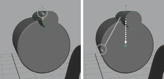
With the bullet-shaped Boolean object selected, press the Insert key (on the keyboard near the Delete key usually) to enter Edit Pivot mode. You want the pivot of the Boolean object to align with the center of the cylinder. You'll do this by holding the V key to enable Snap To Point. At the same time you are holding V, left-click and drag on the green y-axis handle and drag your cursor to a point on the edge of the cylinder that lines up with the cylinder's center. Take a look at Figure 3.4 to see this step illustrated.
You'll notice that instead of following your cursor, the pivot will instead align on the y-axis with whatever point your cursor hovers on.
Your revolver will be a six-shooter, so you will need six indentations positioned around the cylinder equidistantly apart. Since the cylinder is 360 degrees around, you can divide that by 6 to get the result of 60 degrees.
Duplicate the Boolean object and rotate the duplicate 60 degrees around the cylinder. You'll notice that with the pivot placed at the cylinder's center point, its position is placed perfectly aligned as the first one was. Do the same operation four more times to create six evenly spaced duplicates.
Select the six Boolean objects and select Mesh → Combine to combine them all together. This way you can do one Boolean operation rather than six, decreasing the chances of it failing (as was described briefly in the sidebar).
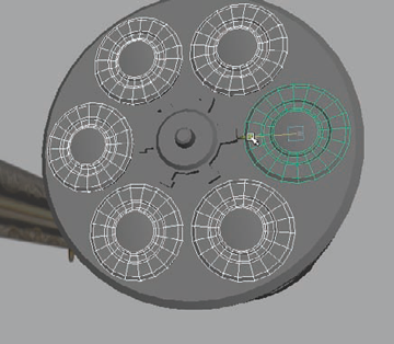
Deselect everything. Select the cylinder first and Shift-select the combined Boolean object second. Select Mesh → Booleans → Difference. You should get a result like Figure 3.5.
Select the Front view. You'll next add an indented channel into the surface, which will be seen later in the normal map that you generate. Enable the Cut Faces tool (under the Edit Mesh menu).
With this tool, you can cut straight loops of edges through geometry based on your camera's view. If you hold the Shift key while doing it, the cut will align vertically or horizontally, depending on which direction you click and drag. On the left end of the cylinder (from the Front view perspective), hold Shift and drag down with the Cut Faces tool to cut a straight vertical edge loop into the cylinder.
Return to the Perspective view. Select one of the edges we just added and select the Select → Select Contiguous Edges menu item. This will select the entire edge loop.
Apply a Bevel to the loop and adjust the Offset to about 0.2, shrinking the new loop to fit the surface seam you'll add here.
Select the Select → Select Edge Ring Tool menu item, and double-click one of the horizontal edges within the new loop of faces, selecting all of the edges within the loop. Press Ctrl+F11. This is the shortcut for the Convert Selection To Faces command. Your selection of edges will convert to a corresponding selection of faces.
Sometimes it's quicker to select an edge loop or ring like this and convert the selection to faces rather than selecting each face you want along the same path.
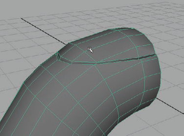
With the ring of faces still selected, extrude them inward, creating a groove running around the cylinder (Figure 3.6).
Center a small cylinder with a beveled end cap on the grooved side of the revolver's cylinder. This small detail will serve as the cylinder's axis for later when you animate it spinning (Figure 3.7).
Now, add one more detail before calling the outer surface of the weapon's cylinder complete and you switch your focus to another area. Create a small rectangular cube that's approximately 0.25 × 0.25 × 0.15 units in size and center it above the cylinder.
Bevel the bottom-facing side (keeping the default offset) and then bevel the side edges, adjusting this offset to be approximately 0.4.
Lower the cube, intersecting it into the cylinder so that the beveled downward facing end is entirely submerged into the surface. Repeat the steps you did with the previous Boolean object:
Edit the pivot point to be aligned with the cylinder's center point.
Duplicate the cube and rotate it 60 degrees.
Repeat until you have six cubes positioned around the cylinder at equal distances.
Combine the cubes together.
Rotate the combined cubes 30 degrees so that they are positioned between the fluted indentations you made previously.
Making sure to select the cylinder first, perform another Difference Boolean operation to carve out the cubes from the cylinder. Figure 3.8 shows the result.


Now that you have the basic form of the weapon's cylinder casing created, you can start adding details and components that are associated with this part. For instance, in the following steps, you'll add the tiny ratchet that will rotate the cylinder casing when the trigger is pulled, and you'll create the bullet caps that will rotate around the cylinder:
Create a new polygonal cylinder and center it with the cylinder casing on the end facing where the weapon's grip will be. Scale it down to be similar in scale to the axis you made in step 22 in the previous section.
Under the polyCylinder Inputs in the Channel Box, change the Subdivisions Axis value to 18. This will give you the number of faces you want for the next step.
To make the cylinder more ratchet-like, you're going to extrude teeth from the side of the cylinder. You want six teeth to coincide with the six bullet chambers that you'll eventually make. Select every third face on the side of the cylinder, giving you six total selected faces (you gave it 18 faces around the axis in the previous step because 18 ÷ 3 = 6).
With the six faces selected, extrude them outward by about 0.04 units. Press the G key to redo your last action and extrude again by about 0.04 and taper the end slightly.
For this particular ratchet, the teeth have small hooks on the ends. You'll simulate this by selecting the left-side face of the last extrusion on each tooth and extruding them outward by about 0.02, tapering the ends and moving them down a bit to straighten it if needed.
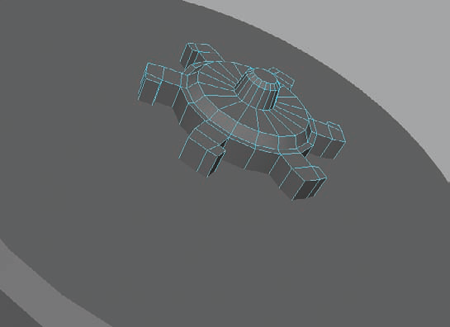
Select the circular front face of the ratchet and perform another Extrude. Scale inward a small amount (with no outward distance extruded). Extrude again, this time pulling outward by about 0.02 and tapering the end. Extrude a third time, scaling this one in by about two thirds of diameter of the circle. Extrude a fourth time, pulling outward by 0.055 and again tapering the end.
Lastly, bevel the tip of this new face, adjusting the offset to be about 0.27. You can see the end result of these steps in Figure 3.9. These last several steps used a series of Extrudes and Bevels to create lots of shape detail in a small space. These details will all serve you well when you bake your normal map later on.
Next, you'll create the illusion of bullets loaded into the cylinder's chambers. Create a new cylinder and position it on the cylinder where the bullets would be visible, between the fluted indentations. Under the Inputs, lower the Subdivisions Caps to 0 to give you clean circular faces on each end.
Select the outward face and bevel it with an Offset of about 0.2 to give it a rounded edge.
Select the end cap face and perform an Extrude. Scale in the extrusion about one third of the cylinder's diameter and extrude again. Indent this extrusion into the cylinder very slightly, around 0.01 units deep.
Extrude this face again and scale inward a bit. Extrude once again, pulling this face back out and tapering it slightly. Apply a new Bevel with an Offset of 0.02 to give the edge a slight amount of rounding. With that series of Extrude and Bevel operations, you should get a result similar to Figure 3.10.
This shape will act as the cap of the bullet that is loaded into the weapon. You don't need to actually see the entire bullet, just the cap to properly give the illusion of a full bullet resting in the weapon's chamber.
Duplicate six bullet caps around the cylinder and the ratchet in the same way you have done before with other things. Remember that you want to keep the bullets between the fluted indentations of the cylinder, as that is where there is room to accommodate them.
With the cylinder and some details created, it's now time to move on to the revolver's barrel. The barrel is basically composed of a couple of cylinders, along with some additional details for the gun site and such.
Create a cylinder in the Front view, and match it to the reference image in length and diameter. Use your transparency-controlled material if you need to. Reduce the cylinder's Subdivisions Caps to 0 to remove those edges. Rename it
Barrel.Duplicate the barrel and lower it down and match the length and diameter to the ejector rod (the barrel-like cylinder beneath the actual barrel). It's OK if the two cylinders intersect. Rename it
Ejector.Select the face on the barrel-end of the ejector cylinder and apply a Bevel command. In the polyBevel Inputs in the Channel Box, increase the Segments to 3 and decrease the Offset to about 0.36. Increasing the Segments gives the Bevel a more rounded edge.
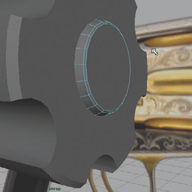
In the Front view, create a cylinder that matches the diameter of the gun site at the end of the barrel. Enter Face component mode and select the lower half of the cylinder's faces and delete them.
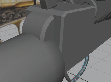
Return to the Perspective view and scale the width of the cylinder to more closely accommodate the barrel and how a gun site would actually be positioned. See Figure 3.11 for an example image.
Back in the Front view, adjust the profile of the gun site cylinder to more closely match the reference image, giving it a more sloped forward side.
Delete the remaining cap edges. Select the two bare faces that result and bevel them, decreasing the Offset to about 0.25. Adjust the gun site's scale as you see fit and rename it
GunSite.Back to the barrel, you'll perform a series of Bevels and Extrusions to create the barrel's opening. Select the face on the "business end" of the barrel and give it a slight bevel, decreasing the Offset to about 0.1.
With the end cap face still selected, perform an Extrude and scale the result about a fourth of the face's radius. Perform a second Extrude and move it into the barrel slightly, tapering the end. Extrude again and move it farther into the barrel. If you were to think of it in real distance, move in about an inch.
Do another extrusion and scale it inward slightly. Do one last extrusion and this time move the face all the way back into the rear of the barrel. When you're done, you should have something like Figure 3.12.

The hammer is the lever that the weapon's owner would pull back to arm the gun before pulling the trigger to fire it. When the trigger is pulled, the hammer would then slam down on the back end of a bullet, firing it from the barrel. This crucial piece of the gun is the next piece you will create.
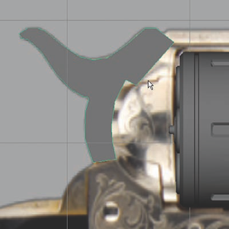
In the Front view, select Mesh → Create Polygon Tool. Using your reference image as your guide, click points down to create a profile shape of the hammer.
You'll have to use your own instincts and any supplemental reference you may be able to find to create the shape of the parts that are hidden in the provided reference. I added on a mallet-like head that I would assume such a piece would have. You can see how mine turned out in Figure 3.13.
In the Perspective view, select the hammer's profile and extrude it out, giving it some thickness. Rename it
Hammer.When the profile was drawn in the Front view, it was drawn on the origin line. Extruding it extruded it from the origin, resulting in the hammer's center no longer being aligned with the origin, or more importantly, with the gun.
With the hammer selected, select Modify → Center Pivot. Then, hold the X key to enable Snap To Grid mode. Move it back to the center grid line, centering it with the revolver parts you've created so far.
Select both of the hammer's profile faces and bevel them, adjusting the Offset to be about 0.8.
The hammer's "head" should be wider than the rest of its "body," so use the Split Polygon tool (from the Edit Mesh menu) and cut in a couple of edges to separate the head from the rest of the shape. Do so on both sides of the hammer.
With these cuts in place, you can adjust the head of the hammer's vertices, widening it. You should have something like in Figure 3.14. You'll return to the head later, but for now, you can move on to the grip.

In this section, you'll focus on modeling the weapon's grip, the handle that will be held by a character in the game. It can be important ahead of time to know how the weapon will be seen in the game before spending too much time detailing the area of a weapon that is covered by the hand of a character model. If the player will never see the weapon grip, there's not much reason to spend too much time on it. However, if the model that the player holds is the same model that is found in the game's world, such as in a gun case, then the time spent detailing is worth it since the gun's handle will be seen.
Make certain the communication between you and your art director is detailed and clear. Many games will have a highly detailed model for the weapon the player holds and a less detailed model for the weapon the player finds within the world. Knowing which one you are working on can save you a lot of unnecessary work, or can save you from lacking the detail that is needed in your weapon's grip. For your project in this book, you can give the grip all the details you want!
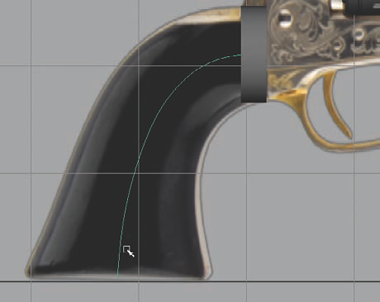
Select the Front view. Create a new cylinder, remove its Subdivisions Caps, and position it where the grip meets the pistol as in the reference image. Rename it
Grip.Draw out a curve from the cylinder through the center of the reference grip to the base, as in Figure 3.15.
In the Perspective view, make certain the Grip cylinder and the curve you've just drawn are both centered at the origin line with the rest of the revolver geometry before continuing.
Just like you did with the tree trunk in Chapter 2, select the face of the cylinder that is touching the curve, hold Shift, and select the curve. You should now have both the face and the curve selected at once.
Perform an Extrude and the extrusion will stretch down to the base of the curve. In the Channel Box, under the polyExtrudeFace settings that are available, scroll down to the bottom and increase the Divisions to around 6, depending on how many points your curve is made of (or whatever looks best in your own scene if it's different from mine).
Back in the Front view, adjust each row of edges on the grip, rotating them for a smoother flow and scaling them up to more closely match the width of the grip in the reference image. You can see my result in Figure 3.16.
Returning to the Perspective view, it's obvious that the scaling you just did caused the grip to flare out comically toward the base. That's all right; you can fix that now. Selecting each row of vertices in turn, scale them in the x-axis (assuming your revolver's geometry is oriented the same as mine) making the geometry thinner. Do so for each row, allowing it to flare outward toward the base.
Feel free to touch up any vertices to help smooth the curvature of the grip and improve the flow of the surface geometry.
Once you have the grip's shape as you like it, select the bottom face of the grip and apply a Bevel, adjusting the Offset to be approximately 0.2 and giving it a rounded lip at its base.
The next step is to model the trigger and trigger guard, a very distinctive area of the gun. Once again, like the grip, the trigger is an area that may or may not receive much scrutiny in an actual game. In fact, many games won't even animate the trigger being pulled since it's so infeasible and the player will never see it. The shower of sparks and smoke that come out of the end of the barrel is usually enough to convince any player that, yes, the gun was fired! For the purposes of this book's lessons, however, all aspects of this weapon will be created with the idea that it will be looked at, even if not very closely.
In the Front view, create a small cube and place it where the trigger guard meets the pistol on the side nearest the grip. In vertex mode, adjust the cube's profile to match the reference like in Figure 3.17.
Select the bottom face of the cube and extrude it down about 0.07 units and scale it in the x-axis to match the width of the trigger guard reference.
Extrude again approximately the same distance and scale it in to match the trigger guard reference's width. Repeat this step again, continuing the trigger guard mesh along the reference.
You could continue to extrude and scale, extrude and scale, along the entire trigger guard if you'd like, or you can use the curve extrude method again. Draw a curve from the last extruded face around to the other side, like in Figure 3.18.
Select the bottom face (the last extruded face from before), hold Shift, and select the curve. With both the face and the curve selected, perform an Extrude. Increase the extrusion's Divisions to about 10 or so, depending on how many points your curve was made of.
Extrude the new end of the trigger guard a few times to match its opposite end.
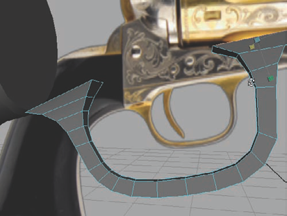
In the Perspective view, scale up the rows of vertices where the trigger guard meets the body of the pistol so that it appears to blend into the future surface of the gun at both ends. You can see how mine looks in Figure 3.19.
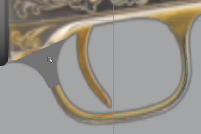
Back in the Front view, create a small cube at the base of the trigger reference. You'll use the curve extrude method again here as well. Draw out a CV Curve from the bottom of the cube through the length of the trigger in the reference image.
Just as before, select the bottom face of the cube, hold Shift, and select the curve. Perform the extrusion and increase the divisions to approximately 5 (depending on how dense your curve is) and increase the taper to 0.6 to make the extrusion smaller as it gets nearer to the tip of the trigger.
Using the Select Edge Loop tool, select the four long edge loops of the trigger guard and bevel them, adjusting their Offset to approximately 0.4.
Do the same for the trigger, beveling the long edge loops to get rid of the hard edges.
Select the bottommost face and bevel it as well to round off the tip of the trigger. Make any vertex adjustments to the trigger guard and the trigger to get them positioned and shaped to your liking.

At this point, you've created the main focal shapes that make up the revolver's overall shape: the barrel, cylinder, grip, trigger and trigger guard, and the hammer. Now you'll focus on the center frame that holds all of these parts together. It's a rather complex shape and will require a bit more modeling finesse than the basic shapes you've created so far. To make things a little more digestible, I'll split the frame into two main parts: the cylinder frame and the trigger frame. You'll start with the trigger frame—the part of the frame that the trigger guard attaches to and that fits into the grip.
Note
Because the modeling of the frame is rather complex, you may find it useful to follow along with the video supplement that is found in the DVD's Video directory as you read the steps to help you understand each step's instruction better.
To help with your focus, create a new layer in the layer bar and name it
HighRes. Select all of the pieces of your revolver, right-click the HighRes layer, and choose the Add Selected Objects option from the marking menu that opens.With all of the existing geometry included, click once on the middle box next to the layer. A T will appear in the box and the geometry will become locked and in Wireframe mode.
This is called Template mode and it allows you to see the geometry without accidently moving or adjusting it. Also, because it is in Wireframe mode, you are able to see through it and do not have the geometry blocking your view.
In the Front view, use the Create Polygon tool from the Mesh menu and create a profile of the trigger frame using your image as a reference. You can see an example in Figure 3.20. Don't concern yourself with the revolver's cylinder. You'll accommodate it in a much later step. Press Enter once you have completed your profile to finalize the Create Polygon action.
Notice in the figure that the bottom of the trigger guard profile doesn't include the extension that is present in the reference where the right arm of the trigger guard meets the frame. This will be added shortly, starting with step 9.
In the Perspective view, you will see the profile in the center of the pistol at the origin. Click on the HighRes layer's T to toggle it to an R. The pistol's geometry comes back into view, but it is still locked.
This is Reference mode, which is identical to Template mode except for the obvious fact that instead of wireframe, the geometry is rendered normally. This is useful if you want to keep the geometry locked but need to see it more clearly.
Extrude the trigger frame profile out about 0.2 units, or until it's a few centimeters past the trigger guard. Rename this object
TriggerFrame.Delete the back face of the frame.
Using the Split Polygon tool, cut an edge as in Figure 3.21, directly across from where the frame extends down to the left arm of the trigger guard to the back of the frame where it meets the grip.
With this edge in place, you can now select the face without selecting that lower section and extrude again approximately 0.3, or until it begins to poke out of the grip where they intersect.
Using your reference, cut in another edge toward the front of the trigger frame where the lower extension (that we didn't use when drawing out the frame in step 3) meets the frame.
Select the two faces shown in Figure 3.22 and extrude them about 0.08 or until they meet the right arm of the trigger guard. Delete the backside faces this created.
This creates a rather obvious gash in the geometry near the trigger. This can be fixed easily by deleting the two faces of the gap and then merging the vertices together to stitch the gap closed.
Select the front edge of this extended piece of geometry and bevel it, giving it a rounded corner.
Select the large face on the side of the frame and bevel it, rounding the edges all around it. Also, bevel the edge loop that runs along the extension below the frame (Figure 3.23).
Make any vertex adjustments you like before continuing. When you're ready, Select the TriggerFrame and duplicate it (Ctrl+D). With the duplicate selected, scale it −1 in the z-axis, mirroring it to the other side of the gun.
Select both halves of the trigger frame and combine them together (Mesh → Combine). With the two halves combined together, select all of the vertices and select Edit Mesh → Merge → Options. In the options, input a low number, such as 0.001, as the Threshold value and press the Merge button. This will merge all of the duplicated vertices running up the middle of the frame together, giving you a clean mesh. You can then delete the center edge loop.
As you can see in the reference, there's a rounded object at the back of the trigger frame that merges into the grip. You can add this in with a simple cylinder with beveled caps inserted into the geometry, as in Figure 3.24.


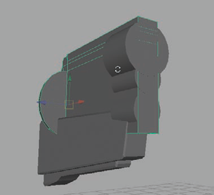
Now that you have the main part of the trigger frame complete, you can move on to the cylinder frame, the part that holds the barrel, cylinder, and hammer together and attaches to the trigger frame. Once again, the shape is rather complex and will require a bit of work to achieve the results you want, so pay attention and study the figure images and the supplemental video to help you follow along.
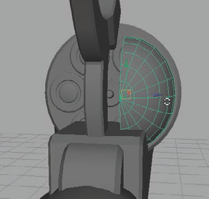
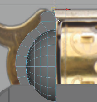
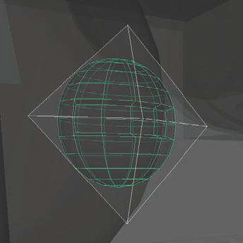
You'll start with the rounded part of the frame that supports the cylinder. Create a sphere and center it on the revolver. Lower its Subdivisions Height to 12 and, in the Front view, position and scale it to match the reference image.
Delete the front-facing half of the sphere and, in the Perspective view, delete half the sphere again, leaving a quarter sphere behind.
Position it as in Figure 3.25, so that it matches the general proportions of the cylinder. You may need to stretch it upward some.
Once you have it positioned the way you want, duplicate it to the other side. There will be a large gap between them. Select both quarter spheres and Combine them together. Then, select the edges that face each other on both halves and select Edit Mesh → Bridge. This will fill in the gap between the two halves, making an elongated shape. You can then use the Fill Hole command (under the Mesh menu) to cap off the open end facing the cylinder.
Next, create two new cylinders that are aligned with the two barrel cylinders but slightly wider in diameter. Position them on the ends of the barrel facing the cylinder and fill the gap between them. Don't worry about them intersecting. You'll fix that later.
Position a third cylinder below these (intersecting is OK here as well). On this one, manipulate its vertices to elongate it, as in Figure 3.26. Make sure all three cylinders are aligned together.
Return your focus to the rounded part of the frame near the hammer. Select the faces running down the rounded hammer side (that you created with the Bridge command earlier). Deselect any that were accidently selected or that are hidden from view. With the visible faces selected, select the Front view and extrude them outward until they match the depth of the reference image. Edit the extruded faces' vertices to more closely match the roundedness of the reference as in Figure 3.27.
Note in the image, the flattened topmost face is pointing up. This will be where the rest of the frame gets extruded from in the next steps.
Select that top face and extrude it up, matching the height in the reference image. Bevel the upper-left corner to round it off and get rid of the hard edge.
Using the Cut Faces tool (still in the Front view), cut through the upper-right corner of the extrusion, which allow you to lift up on the upper corner like in Figure 3.28 and more closely match the shape in the reference image.
Use the Split Polygon tool to continue the edge loops into the surface facing the cylinder.
Now, selecting all of the forward-facing faces running down the middle, extrude them all the way to the right, aligning them with the forward edge of the three cylinders we created earlier (Figure 3.29).
Use the Insert Edge Loop tool, to insert an edge loop in this large extrusion directly in front of where it intersects with the three cylinders. Bevel the top forward edge to round the corner.
Now, you'll do a little bit more beveling to get rid of some more of these hard edges. Select both faces of the rounded parts of the frame (from the original quarter spheres you placed) and bevel them, rounding their edges. Then select the two long edge loops that run along the back and top of the entire frame and bevel them as well to round their edges.
You can now start to do a bit of cleanup. Look back at the three cylinders near the barrel end of the cylinder frame. Select the top cylinder and Shift-select the middle one. Select Mesh → Booleans → Union. This will fuse the two cylinders together, removing the geometry that was intersecting between them. Delete this new object's history and unite it with the third cylinder below it by using another Union. Once again, delete the history.
Next, select the cylinder frame, Shift-select the fused cylinders, and perform another Union Boolean operation. This will merge this entire geometry group together. Rename this fused object
CylinderFrame. You may notice some miscellaneous edges sticking out here and there. Delete them and fix any hanging vertices.Clean up the top of the CylinderFrame, removing the remains of the intersecting that was originally there and replace it with a smoother surface, as in Figure 3.30.
Select the front face of the frame, which is shaped like a deformed figure eight, and bevel it to round off the surrounding edges.
Make any geometry cleanup or adjustments to the shape that you want. When you're done, you should have something like Figure 3.31.


At this point, you have the major forms of the revolver complete. The next step is to add any details and additional components that you haven't gotten to yet to make it look even more realistic.
If you take a look at the reference image, the only major component that you've not made yet is the protrusion coming from the bottom of the ejector rod. This can be made with a simple beveled cube, adjusted to fit the shape and position seen in the reference.
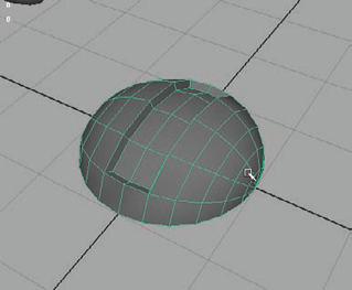
You may also notice a few small screws: one on the ejector rod and a few on the side of the trigger frame. You can create a simple screw head by creating a sphere and deleting half from pole to pole.
Flatten down the half sphere so it's not so rounded. Select a rectangle of faces from the side of the screw and extrude them inward like in Figure 3.32.
Using the reference as your guide, position three duplicates of the screw head on the side of the TriggerFrame. Position the original on the underside of the barrel's ejector rod.
Because of the rounded surface of the ejector rod, you'll need to create a hole for the screw to be placed into. First, use the Insert Edge Loop tool to insert a loop of edges near the end of the rod, where you will be placing the screw. This will keep the hole detail localized to this area of the mesh and prevent it from creating any surface abnormalities along the entire length of the rod.
Create a cylinder and intersect it into the rod where the screw will be. Deselect everything. Select the ejector rod mesh, Shift-select the cylinder, and perform a Boolean Difference operation to carve out a hole in the rod where the cylinder was. Insert the screw head and you're good to go (Figure 3.33).
Now that you have all of the additional details created, you can finally do what you've been waiting to do all this time and carve out the hole in the frame to keep the revolver cylinder from intersecting all that geometry!
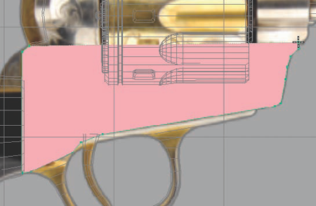
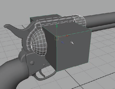
In the Front view, create a cube that is the right size to encompass the entire cylinder object. Scale it out so that it sticks out both sides of the gun and duplicate it in place, making two cubes (Figure 3.34).
You need two cubes because when you perform a Boolean operation, it will remove the negative space object that you use. Since we have two pieces to the frame (the TriggerFrame and the CylinderFrame) we need a cube for each of them.
Deselect everything. Select the TriggerFrame, Shift-select one of the cubes, and select Mesh → Booleans → Difference.
Deselect everything again. Select the CylinderFrame, Shift-select the remaining cube, and do another Difference Boolean. The result of these two Boolean operations carves out a hole for the cylinder to sit in unimpeded.
Now that you've carved out the frame, there's only one small detail left. You'll notice in the reference image that the top of the grip has a metal surface.
In the Front view, use the Cut Faces tool from the Edit Mesh menu to carve a horizontal edge loop through the grip geometry where the metal surface is in the reference image.
Select the faces that make up this carved section of the grip. Extrude them inward a small amount. Extrude them again back outward and scale them in slightly. You should get a result similar to Figure 3.35.

Now that you have the high-resolution revolver, you can begin creating the low-resolution version. The low-resolution revolver will be the model that is used in your fictional game for this project. The high-resolution mesh was created simply to generate texture source details from it. These textures will be applied to the low-resolution mesh to create the illusion of detail, just as you did in Chapter 1 with the Brick Wall project. This is a typical procedure, not only in weapons but in game art in general.
However, don't feel like all that work is wasted on something you'll never use. You can extrapolate a large portion of your low-resolution geometry directly from the high-resolution geometry, making this mesh much faster to create in most cases.
First, select all of your high-resolution geometry and make certain it is all included in your HighRes layer by right-clicking the layer and choosing the Add Selected Objects option from the marking menu that opens.
Next, with all of your high-resolution geometry still selected, apply a new Lambert material by right-clicking; from the popup marking menu, going to Assign New Material → Lambert.
Make the Lambert's color dark, but not completely black. You still want to be able to make out the surface detail of your model.
You'll start with the grip. Select it and duplicate it. With the duplicate selected, right-click and select Assign Existing Material → Lambert1. This assigns the duplicate grip the default gray material.
With the duplicate grip still selected, enter Vertex component mode and select all the grip's vertices. Over in the Toolbox on the left, double-click the Move tool to bring up the Tool Settings dialog box. Under the Move Axis setting, change it to Normal.
The Normal setting on the Move tool allows you to move a vertex along the surface direction of its individual position. The regular X, Y, and Z directions on your gizmo get replaced with U, V, and N, where N represents the Normal direction.
With all the grip's vertices select and your Move tool set to use the Normal setting for its Move Axis, click and drag on the N-labeled handle on your gizmo. You'll notice that all of the vertices get pushed in or out along the surface direction. What you want to do with your duplicate grip's vertices is push them outward so that the mesh is slightly larger than the original grip mesh. The original grip will sit inside the duplicate grip.
Having a dark material on the original and a lighter gray material on the duplicate helps you easily tell when the lighter gray color of your duplicate completely envelopes the dark color of the original. Then you can know that you've pushed the duplicate out far enough to stop.
After pushing the duplicate grip out to encompass the original, you can then modify its geometry to remove the detail, making it lower resolution. The main detail we want to remove is the horizontal cut that you inserted into the original grip earlier. Select those edges and delete them, removing them from the mesh with Edit Mesh → Delete Edge/Vertex. Also, if there were any geometry completely hidden from view, that is, intersected within another piece of geometry and unseen, those faces can be deleted as well.
In the Layer Bar, create a new layer and name it
GameRes. This will be the layer for all of your low-resolution geometry. Select the new grip, right-click the GameRes layer and Add Selected Objects.
Keep in mind that even though some parts of the mesh may have a lot of geometry to create smoothness (such as the roundness of the barrel cylinder), don't remove that geometry just yet. Maintaining that roundness will assist in creating texture sources in a later section. Afterward, that density can be adjusted easily. Also, don't worry about creating a low-resolution version of the tiny screws and such as they will be details included in the normal map.
The barrel of the gun is essentially a hollow pipe. In the low-resolution version, that is a detail that you won't need because that kind of detail would be completely hidden from view—especially if the gun would be pointed away from the player most of the time when they are using it!
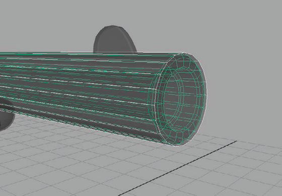
Once you have your duplicate geometry pushed outward along its vertices' normals, you can continue here. Select the face way down at the end of the interior of the barrel. Press the shortcut Shift+. to grow your selection. Keep growing your selection until you have the entire interior of the gun selected, along with the end of the barrel (but not the long cylinder that makes up the barrel's exterior). Delete them.
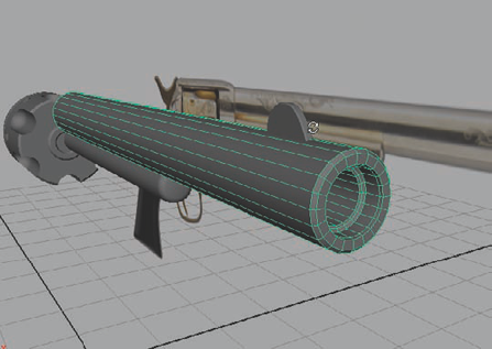
Select the edges bordering the open end of the barrel and select Mesh → Fill Hole to cap the end of the new barrel. Move the end of the barrel out until it covers up the end of the high-resolution barrel. You should end up with something like Figure 3.36.
In this image, I'm using Xray mode to demonstrate the two meshes on top of each other. The green highlighted mesh is the original high-resolution geometry and the white highlighted mesh is the new, low-resolution geometry surrounding it.
The cylinder is a relatively complex object. It may even be easier to re-create it from scratch for the low-resolution version. However, I'll continue to use the method described here for this lesson to give you an alternative.
Once you have your duplicate geometry pushed outward along its vertices' normals, you can continue here. The first detail you can remove is the carved-in groove. That's a simple matter of selecting the edge loops and removing them with the Delete Edge/Vertex command from the Edit Mesh menu.
Next, select the faces that make up the six fluted indentations around the cylinder and delete them, leaving empty gaps where they were. You'll fill these in a bit later.
Before doing that, you can take care of the six square-shaped indentations that are also around the cylinder. Select the bottom face for each of them and press Shift+. to grow your selection until you have all the indentations' faces selected. Delete them.
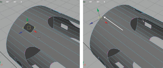
Select the vertices for one of the holes left behind. Hold the V key to enable Snap To Point mode. Click and drag the vertices to the side to snap them along the edge that they intersect (Figure 3.37). Do this for all six holes.
Use the Merge (Edit Mesh → Merge) command to merge the stacked vertices together, fusing them each into one point.
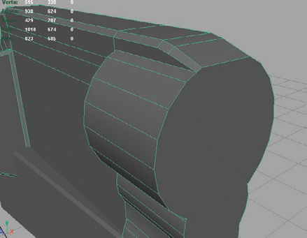
Now that those holes are gone, you can focus on refilling the cylinder's fluted notches, this time, with a much lower resolution mesh. If you go into Vertex component mode, you'll see that there are a lot of vertices running along the edge of the holes that are left behind from when you deleted the faces that were there.
An easy way to do this is simply to select all of the vertices that make up the curved area of the notches and press the Delete key on the keyboard. You'll notice that all of the hanging vertices (that is, vertices without edges) are deleted while the others are left alone. However this deletes too many, so undo that if you did it.
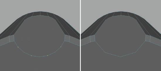
Select all the curved vertices again but this time deselect the vertices at the points where the notches begin to curve as well as the second vertex from there on each side of the curve. See Figure 3.38 for an example.
With those vertices deselected, you can delete the rest of them and end up with a low resolution result that you can work with. It won't be nearly as smooth, but the normal map later will help fake it.
On the other end of the notched gaps, you can do something similar, selecting every other vertex and pressing delete (Figure 3.39).
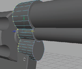
Select the edges on the back of each notch and extrude them toward the front, so they are aligned with the first row of vertices that make up the curve of the notches to begin filling in the holes.
Extrude the edges again and begin point-snapping the ends of them to the notch curve to fill in the gap. Once the gaps are filled, you can use the Merge command to fuse the stacked vertices together (Figure 3.40).


The rest of the gun is pretty much a process of following the prior listed steps. If you get lost, feel free to refer to the video supplemental on the DVD. The videos in question are named Pistol_Texturing.
The main detail left to go over is the screws on the side of the TriggerFrame mesh. You don't necessarily need to devote an entire half sphere to each screw, even if they were low poly half spheres. Instead, you can use small pyramid shapes that are textured appropriately later with opacity and normal maps to effectively fake the details!
First, select Create → Polygon Primitives → Cone. Decrease the Subdivisions Axis down to 4, turning the cone into more of a pyramid shape.
Delete the bottom face (you won't need it), and squash the pyramid down so it isn't so tall.
Position the pyramid over one of the screws as in Figure 3.41. Do so for all three screws. (Not the one on the ejector rod. That one will be handled strictly by the normal map.)
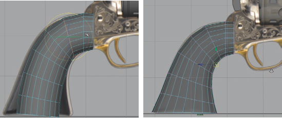
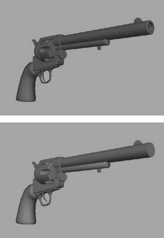
That pretty much wraps up the work for creating the low-resolution revolver. When I finished, my high-resolution revolver was approximately 10,000 polygons while my low-resolution revolver was about 2,900 polygons, which is very doable in most next-generation action games. Figure 3.42 shows them side by side. If need be, the geometry density can be taken down even more without losing too much of the low-resolution gun's overall shape, but I'm going to leave mine here for now. You can continue to lower the geometry of yours as much as you want!
The next step is UV mapping the low-resolution geometry to get it ready for texturing. You'll start with the cylinder.
Select the cylinder mesh and press Alt+H to hide all the other geometry so you can focus your attention.
Select Window → UV Texture Editor to open the UV Editor you'll be working in. I like to place the UV Editor window on the right and have my working camera view on the left.
You can see, with the cylinder selected, that the UVs are a mess in the editor. It's up to you to get them cleaned up. First, select the left cap face (facing the grip side of the gun) and select Create UVs → Automatic Mapping. Because the face is round, it lays it out as a circle. Select the circle of UVs in the editor and move them to the side to get them out of the way.
Select the other cap face and repeat the Automatic Mapping, then move the result to the side.
With the two caps mapped, you can now map the cylinder itself. Select the remaining faces and select Create UVs → Cylindrical Mapping. Take a look at the result in the UV editor.
If your results are anything like mine, it probably doesn't look right. The cylindrical mapping manipulator is not aligned with the cylinder, creating a warped result.
Click the small red crosshair located at the bottom left of the cylindrical mapping manipulator. Clicking it brings up the transform gizmo, which allows you to rotate the manipulator 90 degrees, thereby aligning it with the cylinder and creating a much nicer result.
Continue to UV map pieces of the revolver using methods like this as well as what you learned in Chapter 2 when you UV mapped the trunk of the Savannah tree. If you get stuck or lost, you can refer to the video supplement found on the DVD. Eventually, you'll have everything UV mapped and strewn about the UV editor. You'll then need to lay the different UV shells out in the editor.
The idea behind laying out UVs is to make as efficient use of the UV space available as possible, as well as maintaining proportional UV density throughout the object. For instance, if the UV layout of the cylinder is much smaller in scale proportionately then the UV layout of the grip, it'll look too blurry or the grip will look too crisp—one or the other.
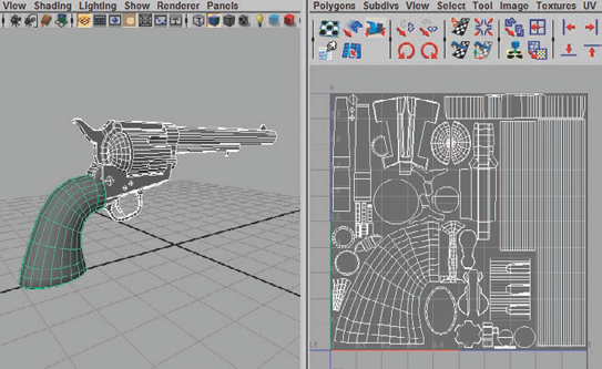
You can see my resulting UV layout in Figure 3.43. Notice that I divided the UV shells of the grip and the cylinder and layered them on top of each other. This way, each half of the grip and cylinder can share UV space and share the texture.
After generating texture sources already for the previous two chapters, you are getting the hang of it, I think. You should be aware of just a couple of differences to pay attention to when generating texture sources for moving objects.
The AO maps that you generate for the moving parts should be generated separately from the rest of the model. Since the generated result is what you are using to bake in shadow information, you obviously can't have a shadow baked into, for example, the cylinder because you would notice it move unnaturally. So, when generating your source textures for Ambient Occlusion and Normals, generate the trigger, hammer, cylinder, and bullet caps separately.
Also, because in my example I'm stacking UV shells, you'll need to separate the stacked geometry and generate the texture sources for each half by itself. Then you can combine them back together afterward. So, in my example, I would need to separate half of the grip and cylinder before generating my texture sources. Eventually, I ended up with what you see in Figure 3.44, an AO source and a Normal source, both 1024×1024 targa files.

Animation for a weapon, or any game prop for that matter, is just like animating anything else in games. The geometry is rigged with a skeleton and then animated by an animator on the team. Depending on how large a team you are working on, that animator could very well be you! So, it's important to understand at least some of the basics. With that in mind, you'll focus on creating a simple animation of the revolver firing.
Note
Just so we're on the same page with this lesson, browse on the DVD to the Chapter 3 project directory and open the Maya file named Pistol13_AnimationStart.ma. This will be the starting point for animating the gun. It consists of the main revolver all joined together with its separated moving parts:
Revolver (main frame with grip and barrel)
Hammer
Cylinder
Trigger
Before beginning the actual rigging and animation, you'll need to do some minor animation setting adjustments. Open the Preferences window by going to Window → Settings/Preferences → Preferences or by clicking the Animation Preferences button near the bottom left of the screen, next to the AutoKey button.
In the Preferences dialog box, open the Time Slider section under the Settings heading in the list on the left side. Check and see what the Playback Speed setting is set to. You want it to read Real-Time 30 fps (frames per second). If it says 24 fps instead, you'll need to make an adjustment.
Open the Settings header in the list on the left and change the Time setting to NTSC (30 fps). The majority of games are animated to this speed. If your particular project in the field requires something else, make sure your art lead informs you.
Once you have the speed set, you can click Save and return to the project.
Press F2 to switch to the Animation menu sets. Select the Front view and press the 4 key to enter Wireframe mode.
Select Skeleton → Joint Tool to start creating skeleton joints. Place a joint near the center of the grip and press Enter to finalize its placement.
Select the joint and duplicate it. Place the duplicate near the base of the trigger where it meets the frame of the weapon. Duplicate the joint again.
Place this duplicate near the base of the hammer where it meets the frame of the weapon.
Duplicate the joint once more and place it at the center of the cylinder.
Rename the joints
Root,Trigger,Hammer, andCylinder, respectively.Once you have them placed the way you want, select all of the joints except the Root joint. Shift-select the Root joint and press the P key on the keyboard. This will parent the other joints to the Root (Figure 3.45).
Select the cylinder and rotate it 30 degrees. After all, when the gun is loaded, the bullet needs to be lined up with the barrel!

Many games handle skeleton binding differently. Some simply parent geometry to joints if it's not going to deform. Other games require a Smooth Bind, whether it will deform or not. For this project, assume the latter and use Smooth Binding.
Select the revolver geometry (all of the non-moving parts) and Shift-select the Root joint. Select Skin → Bind Skin → Smooth Bind → Options. Change the Bind To option to Selected Joints and the Max Influences to 1.
Smooth Binding is generally used for deforming geometry. However, for rigid meshes like props, you don't need anything to bend or deform. To ensure that doesn't happen, the above settings in step 1 will force the geometry to be bound 100 percent to the selected joint with no chance of being influenced by another.
Click Bind Skin. You can test this by selecting the Root joint and rotating it. The revolver geometry should follow suit.
Repeat these steps with the Hammer, Trigger, and Cylinder, binding them to their respective joints.
Now it's time to start the animation! For the firing sequence, you'll need the following to happen in order:
The hammer pulls back, rotating the cylinder into place.
The trigger is pulled.
The hammer releases, and the gun recoils.
The trigger returns to the original position.
Easy, right?
Select Frame 1 in the Time Slider. Select the Hammer joint and set keys for its Rotation channels by selecting them in the Channel Box, right-clicking, and choosing Key Selected from the menu that opens.
You can probably time it out in your head, but for this lesson, you can assume it takes approximately a third of a second to pull the hammer back. Since we set it to 30 frames per second, select Frame 10 and rotate the Hammer joint about 40 degrees in the Z direction, pulling back into a cocked position.
When the hammer is pulled back, what is actually happening is the cylinder is being locked into place with a fresh bullet. So, with that in mind, we want the cylinder to rotate as the hammer is being pulled.
Select Frame 3 and set keys for the Cylinder joint's rotation channels.
Then, select Frame 11 and rotate it 60 degrees. You'll recall that 60 degrees is the distance between bullets on our cylinder, so this will effectively portray the cylinder being primed for firing (Figure 3.46).
With the gun now "loaded," go to Frame 30. Select the Trigger joint and set keys for its Rotation channels.
You can perhaps picture that it takes only a third of a second to pull the trigger, so go to Frame 40 and rotate the Trigger back about 30 degrees to a good position for firing.
The hammer shouldn't fire immediately. That would mean the trigger was a "hair" trigger with no give in it. Wait until Frame 35 and set another keyframe for the Hammer's rotation channels. This is halfway through the trigger's pull-back animation.
The hammer would clap down extremely quickly, so go to Frame 35 and rotate the Hammer back to 0 (its original location) and set another keyframe here.
This is about when the gun should recoil from the energy output of the gunpowder igniting! Go to Frame 37, about halfway through the Hammer's release animation. Set a keyframe for the Root joint's Rotation channels.
Go to Frame 40. Rotate the Root back about 20 degrees, as if it were kicking backward from the shot.
Go to Frame 50 and rotate the Root back the other way approximately −20 degrees, as if the person holding it overcompensated when trying to push the gun back into an aimed position.
Go to Frame 60 and return the gun to its original position and set a new keyframe.
Lastly, select the Trigger joint and set a keyframe at its last position for Frame 45. Then move forward to Frame 55 and rotate the Trigger back to its original position and set a new key.
If you rewind the animation and press Play, you should see an effective firing animation! All it needs now is a blast of particle effects bursting out of the barrel and a good sound effect to really sell it. But that's a different department. You can check out the Pistol15_AnimationFinal.ma file on the DVD to see my final animation as an example.
Hopefully by now, some of the patterns of creating game art are becoming apparent to you. While many steps may be repeated, they are never necessarily exactly the same. There are definitely differences that can be found on a per-project basis. Following along with these different projects should introduce you to many of those variables. Creating weapons can be one of the more fun props to create for an environment artist; second only to vehicles, perhaps!
