A basic interior game environment CONSISTS of some combination of walls, ceilings, and floors. For the most part, the way you create any of these three surfaces will follow standard procedures, but they definitely have differences that you need to consider. These surfaces (and I'll refer to them as backgrounds from now on) will be forming the foundation from which you'll be building all other props and environmental visuals in your interior spaces. You definitely want to treat your backgrounds consistently and to the highest quality.
In this chapter, the term backgrounds refers to 3D surfaces that serve the basic function of a wall, a ceiling, or a floor. The way a game handles such surfaces can differ depending on the game editor being used, if any. A game's editor is typically the program used to create the levels in a game. Assets from applications such as Maya are imported into the editor to be used. The level can then be exported from the editor into a format the game itself (or the game engine) can understand and run as a playable product. Many types of editors exist, and not all game engines use them in the same ways. Your art lead will fill you in on the specific idiosyncrasies of the project you are working on.
For instance, in Tomb Raider: Anniversary (published by Eidos), there wasn't an editor involved at all. All of the game environments were created directly in the 3D program and exported into a format the game could understand. In games created with the Unreal engine (developed by Epic Games and licensed to other game developers), developers used the Unreal Editor to create shapes and volumes of surfaces that can be textured to form background surfaces. Other editors have terrain generators that can create large expanses of ground or water volumes. And in some games, certain background surfaces aren't even needed. In Diablo II (famously developed by Blizzard Entertainment), the game's overhead, isometric perspective eliminated the need to create ceilings.
Most games, no matter what kind of editor they use or what type of backgrounds they need, will adhere to very specific rules for creating them. These can vary greatly between projects, but most do have two commonalities. They will have specific sizes and shapes and they will tile.
When something tiles, it means several assets (textures, models, and so on) can be laid end-to-end and there will be no gaps or visible seams between them. This applies to all background surfaces as well as textures. Walls need to tile from left to right, while ceilings and floors need to tile from all four directions. I'll go into much more detail about tiling later in the chapter.
You also need to regulate the specific sizes of background shapes you create. If environment artists were to create background pieces without such regulations, it would make the process of tiling them in a game level much more difficult and time-consuming. It can even change the way a game can be played. If it is specified that a game character can climb up onto platforms that are no higher than eight feet tall, then it's important that such platforms are created in that manner, as well as making sure areas that shouldn't be climbed are higher than eight feet. These different sizes can also vary between games, but whatever size conventions are used, they must be used consistently.
Background surfaces will typically be used throughout an entire game. The wall that is used in a castle in level one is actually the same wall being used in the dungeon in level two. It just has a different texture applied. The floor? Same thing. The floor that represents a marbled foyer is the same one for the hardwood floor in the forest cabin with different textures applied. And so on for ceilings. In this example, these would be in your game's set of "man-made" background elements.
The more varied in style the backgrounds a game has, the more sets of background pieces will need to be made. For example, you'd need a different set of background pieces for your cave environments or your sewer environments, and so on. But all the pieces within each set should tile together with others from the same set. A custom piece could then be created for the purpose of merging two sets. A cave entrance piece, for instance, could lead from one environment set into the cave environment set seamlessly.
Understanding this, you can see that it's actually the textures that are the most important part of making the background elements. While there are just a handful of different shaped wall segments, there can be dozens, if not hundreds, of textures that could be applied to drastically change how each wall looks. Start tiling the backgrounds end-to-end, placing floors and ceilings, adding props and lighting, and before you know it, you have a game environment on your hands!
But hold on. Don't put Maya away just yet! The path toward creating tiling textures for your backgrounds still requires some 3D work. You'll understand better when you start your first project. You'll start simple, with a grungy, dirty brick wall.
You'll use Maya to create a brick wall. Without worrying about polycounts, UVs, or any other game art restriction, you'll create a high-resolution wall of 3D bricks. Once that's completed, you'll then create your low-resolution wall. This low-resolution wall will be the actual piece that will go into your fictional game. Then, using your high-res geometry, you'll create your textures in a 2D image program, such as Adobe Photoshop. But I'm getting ahead of myself.
The first step of creating a simple brick wall is creating a simple brick. In this and in all of this book's projects, you'll be using polygons for both high- and low-resolution models. You'll also use this standard: one unit in Maya is equal to one foot (or 12 inches) in real-world space. A quick look into architecture will show you that a typical brick is 8 × 4 × 2.25 inches. For your purposes, you don't have to be incredibly accurate. The only real criteria that most game artists have for their final results are as follows, unless of course something else is important to your game's play:
Does it make sense?
Does it look cool?
Does it work in the game?
If those criteria are all met, for the most part, you've got a winner!
Note
Before starting, make sure you set your project to your project directory by going to File → Project → Set.
Since you know the typical dimensions of a standard brick, you'll use that as your starting point and create a brick:
When first opening Maya, make sure your Menu Set is set to Polygons.
Select Create → Polygon Primitives → Cube → Options.
In the options, set Width to 8, Height to 4, and Depth to 2.25.
Click Close.
Hold the Shift key and click near the origin of your scene. This will create the cube with the entered dimensions rather than creating it interactively. A cube will be created using the set dimensions. Go ahead and hold the X key and move the cube to the origin. Holding the X key while moving an object enables Snap to Grid mode, which allows you to snap the cube to the origin.
Rotate the cube 90 degrees in the y-axis to make the forward-facing side of the brick point in the positive X direction in your scene. You can also move it up 2 units in the Y direction to make it appear to set upon the grid like a shelf. This is mainly to make viewing your scene easier.
With the cube selected, select Edit Mesh → Bevel. This will apply a Bevel command to your geometry. In the Channel Box on the right side of the screen, under the Inputs list, select the new polyBevel1 item that has appeared, if it's not selected already.
Under polyBevel1 is a list of different settings that you can adjust for your new bevel. Change Offset to 0.15, Segments to 2, and Smoothing Angle to 90.
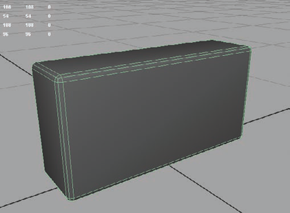
You should have a box with rounded edges, like in Figure 1.1.
Note
Your grid spacing may vary from mine, depending on what your settings are. My settings (you can find yours under Display → Grid → Options) have Length and Width set to 12, Grid lines every 5 units, and Subdivisions every 5 units. In general, it shouldn't affect the project negatively if your settings are different.
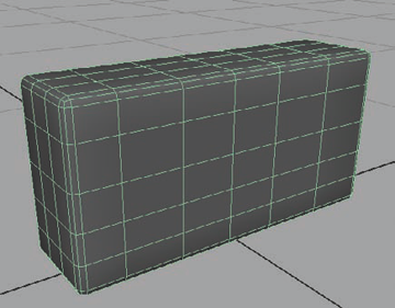
Change to the Front viewport and select Edit Mesh → Cut Faces Tool. Holding the Shift key to make straight cuts, click and drag to the right, cutting four or five cuts into the front of the brick, dividing it roughly into equal slices along its entire height. Do it again vertically, dividing it lengthways in the same manner. In the Side view, do the same: Cut two or three vertical slices into the brick. You should end up with something like what you see in Figure 1.2.
Duplicate this brick two times, giving yourself three pristine bricks to start with.
Now that you have some very clean-looking brick shapes, you'll dirty them up a bit. You'll add some pockmarks, chipped-off chunks, and so on, so that your bricks look like they've been out in the elements for years and years.
Select Create → Polygon Primitives → Sphere. Create a small sphere next to your first brick.
In its Inputs, under the polySphere1 options, change both Subdivisions Axis and Subdivisions Height to 8.
With the right mouse button (RMB), hold on the sphere and choose Faces from the marking menu, turning on Face component mode.
Select and delete the faces that make up the lower half of the sphere.
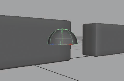
Press F8 twice to return to Object mode. With the half sphere selected, select Mesh → Fill Hole. This will cap the hole that you left behind, creating a solid half sphere (Figure 1.3).
The half sphere will become a negative-space object. It is going to be used to carve out pieces of your currently pristine bricks. You first need to knock it around a bit—mess the sphere up so that it looks more like a rock than a smooth round shape.
Make sure the Keep Faces Together setting is selected in the Edit Mesh menu. Entering Face component mode again, select the sphere's remaining faces (not selecting the cap face you just created with the Fill Hole command) and select Edit Mesh → Extrude. Pull these new faces out and scale them inward.
In the extrude face's Inputs in the Channel Box, adjust the Random attribute until you get a suitably randomized result without any faces sheering.
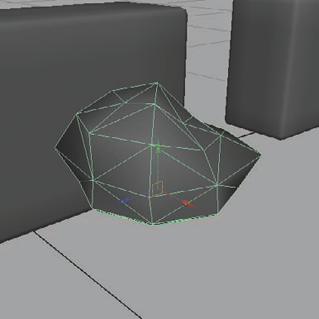
Back in Object mode, select Mesh → Triangulate (Figure 1.4).
The main goal of this step is to get an organic, natural-looking shape. The only thing you don't really want is to have sheer edges that are overlapping or intersecting each other. You'll go one step further in making the sphere look a bit more messed up to get a few more surface variations.
Select a clump of three or four faces on the top of the sphere and select Edit Mesh → Extrude to extrude them up. Scale them inward a bit. Do the same on another clump of three or four faces, extruding them up at a different height, scaling them inward slightly.
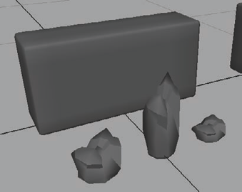
Duplicate your resulting rock-like object two more times. Leave the first as it is, but scale the second up to be tall and skinny. Scale the third down to be short and squat. You should have something like the objects in Figure 1.5.
Start duplicating and positioning these rocky objects around your first brick, slightly intersecting. Rotate them so that the rocky tops are the sides that are intersecting into the brick shape. Think about where a brick would be the most weathered. Focus on the corners and along the edges more than the flat surfaces. Don't be afraid to clump the rocks together, intersecting each other. You can also continue to scale the shapes further if necessary.
Do the same for the second brick, making certain to intersect the rocky shapes differently than you did for the first. Don't position them on the third brick at all.
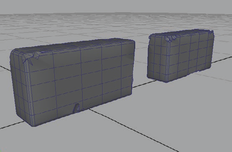
Just remember, don't intersect them too deeply. You mainly want the bricks to look as if they have been chipped, not gouged out completely! When you're done, you should have something like Figure 1.6.
Now for the fun part! Select your first brick and Shift-select one of the intersecting rocks that are around it. Select Mesh → Booleans → Difference. The rock should disappear, carving out of the brick wherever the rock intersected the brick.
With the brick selected, Shift-select another rock and press the G key. (The G shortcut key will redo whatever action you last did.) Continue to carve out the remaining rocks from both bricks, making sure that the brick is selected first and then a rock is Shift-selected before pressing the G key.

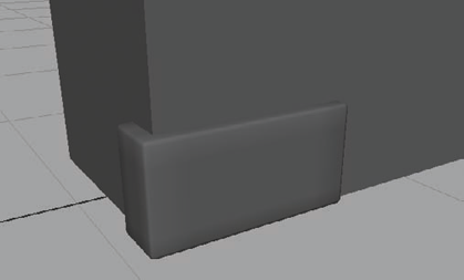
If, when you are done, you find that you would like more chipped-away parts or that some of your rocks were intersecting the bricks too deeply and too much brick has been carved away, undo (Z) and readjust them until you get a result you like. Eventually, you should get a result similar to Figure 1.7. With these three bricks, you'll have enough variation that your brick wall shouldn't look too repetitive or boring.
Now, you'll lay out your bricks to form your tileable wall, from which you will be able to create your brick wall textures. The important part is laying them out in a way that doesn't look too mechanical. The story you are trying to tell is that these bricks weren't laid out by a machine but by a flesh-and-blood masonry worker, in other words, someone who couldn't possibly align bricks next to each other perfectly.
First you'll get organized. Select all three bricks and make sure they have their pivots centered by going to Modify → Center Pivot.
Select the clean brick—the one without any nooks or crannies carved out of it. Select Edit → Group. This command places the brick within a group. Once you have a bunch of clean bricks lying around, it'll make it a lot easier to select them all if they are grouped. Name your new group
CleanBricks.Repeat this with the other two bricks. Name the first group
DirtyBricks1. Name the second dirty brick's groupDirtyBricks2.Now, you'll create a surface to place the bricks against. Select Create → Polygon Primitives → Cube. Follow the onscreen instructions and lay out a cube. Once the cube is in place, click its polyCube1 Inputs in the Channel Box and set the following: Width: 10, Height: 100, Depth: 100.
Reposition the cube to be set on the grid.
Grab your clean brick (don't select the CleanBricks group, just the brick itself). Position it at the bottom-left corner of the blank wall, approximately as in Figure 1.8.
Duplicate (shortcut Ctrl+D) the brick and move it to the right, leaving what would be about a 1-inch gap between the first brick and the second.
Immediately after placing the duplicate brick, you can press Shift+D. This is the shortcut for Edit → Duplicate With Transform, which will make a new duplicate and automatically move it the same distance as you moved the previous duplicate. Continue pressing Shift+D until you have a complete row of bricks that stretches across the entire blank wall.
Press Shift+D one more additional time to make an extra brick on the end of your line of laid bricks.
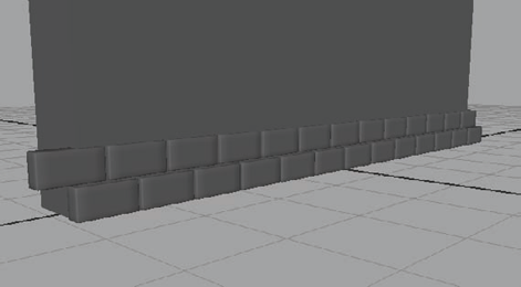
Select all of the bricks you have so far and press Ctrl+D to duplicate them all and raise them up, leaving about an inch gap between the two rows. Now, move the entire row of new bricks to the left until the left-most brick is extending about halfway beyond the blank wall's surface. The extra brick you made in step 8 is now filling in what would have been a gap on the far-right edge of your second line of bricks (Figure 1.9).
Select both rows of bricks now. Press Ctrl+D to duplicate both rows and move these new bricks up, also leaving about an inch gap between the old rows and the new ones.
Press Shift+D to Duplicate With Transform. Continue until you have filled the empty wall's space as in Figure 1.10.
Well, you have a full brick wall now, but that was a little too easy, don't you think? And what about your dirty bricks? How do you fit them in? And how did your masonry worker set these bricks out so uniformly? You'll add some random dirty bricks and natural chance into your brick layout.
Start selecting bricks at random, holding down the Shift key to add each additional brick to your selection. Try to really be random about it and don't let your selection fall into any sort of pattern. Try to select at least one or two bricks on each row. Keep selecting bricks until you have selected about 10 to 15 percent of them. If you see any of your selected bricks in an unintentional pattern, don't be afraid to deselect them and choose an alternative by Ctrl-clicking them. Once you have a selection of bricks that you are happy with, press Delete to get rid of them.
Go into the Side View and turn on Wireframe mode (by pressing the 4 key). In Wireframe mode, you can more easily see where your new gaps are in the brickwork. Select one of your dirty bricks (once again, only select the brick, not the DirtyBricks layer it belongs to). Move it into one of the vacant spots on the wall.
Press Ctrl+D to duplicate it and move it into another empty spot. Don't worry about lining it up perfectly with the bricks on either side, because the goal is imperfection. Don't fill every gap, but fill about half the available empty spots with duplicates of this brick.
Do the same with the second dirty brick, duplicating and repositioning it to fill in the rest of the empty spots.
Now, you have a good random percentage of bricks that have some imperfections, nicks, scratches, and the like. However, they all are kind of the same nicks and scratches. You'll add another level of chance to your layout.
Select one of the clean bricks and press the up arrow on the keyboard. This will step up the brick's hierarchy to select the CleanBricks group. Press Ctrl+H (or Display → Hide → Hide Selection) to hide the clean bricks, leaving just the dirty bricks visible.
Now, select one of the remaining dirty bricks and press the up arrow as well, selecting its group (in my case, I selected DirtyBricks2). Select Window → Outliner. The Outliner is a window that simply displays everything that is currently in your scene. In the Outliner, scroll down until you see the group you have selected. Click the + symbol next to the group name to expand the group and to see all of the group's contents (in my case, all of the dirty bricks within the DirtyBricks2 group).
Holding Ctrl, select every other brick in this list and rotate them all in the Y direction 180 degrees, flipping them completely around. The side of these bricks that was hidden from view is now revealed on the wall. Deselect them.
Holding Ctrl, select some of these bricks at random, whether or not you just flipped them around, and rotate them in the X direction 180 degrees, flipping them upside-down. Deselect them.
Lastly, make another random selection, whether or not you have made any change to them yet, and rotate these in both the X and Y directions by 180 degrees. Deselect them.
What these last couple of steps did was take some of the dirty bricks from the DirtyBricks2 group and flip them around completely, some of them upside-down, some of them around and upside-down. Some bricks were left completely untouched. This gives you a randomized look, even though they are all the exact same brick.
Repeat steps 6–8 on the bricks in the other dirty brick group (in my case, DirtyBricks1).
If you look and see spots that, even after all those steps, still have a couple of identical bricks right next to each other, go ahead and rotate one of them around, upside-down, or both to prevent that kind of pattern.
Press Ctrl+H (or Display → Show → Show Last Hidden) to unhide the clean bricks.
Note
If you've hidden other items or turned Maya off since you last hid the CleanBricks group so that it is no longer the "last hidden" item, you can display it by going to Display → Show → Show Geometry → Polygon Surfaces
What else can you do to add interest and chance to your brick wall? So far, you have a nice smattering of bricks that aren't pristine in your wall, but they are still very regularly spaced and placed. Except for your dirty bricks, which you intentionally didn't align perfectly, the rest of them are perfect and pristine in how they are placed in relation with each other. You'll change that now.
Return to the Side View and once again hold Shift as you select a random selection of both clean and dirty bricks. Go ahead and choose about 15 to 20 percent of them, trying not to pick them with any sort of pattern. If you select any brick that extends beyond the left or right edge of the wall, make sure you also grab the one on the opposite edge of the wall to make sure your final result tiles properly.
Move these bricks outward, making them protrude from the wall slightly more than the rest. Then, deselect them.
Select another random 20 percent, making sure that you again select the brick on both sides if you select one that extends beyond the edge of the wall, and move these slightly down and to the left. Then, deselect them.
Repeat the selection process, ensuring no pattern and not worrying about whether or not you have already selected any brick more than once. Move these bricks inward slightly, so they don't protrude outward as much as the rest.
Select another set of bricks randomly, and move these slightly up and to the right.
Take a look at the results. If you see any bricks that are intersecting or touching, fix that by moving them apart.
Now, select just a few bricks. No more than 10. Rotate these very slightly, tilting them to the right.
Repeat this, selecting no more than 10 bricks randomly, and rotating them slightly to the left and slightly tilting downward. You can move these bricks outward some as well if you'd like, but not cartoonishly so. They shouldn't look as if they are about to fall out of the mortar.
Double-check to make certain no brick is protruding too far out, is too close to any of its neighbors, or is intersecting, and reposition any offending brick(s) if necessary. Also double-check to make certain that any bricks that are extending beyond the wall on the left or right edge match the position of their counterpart brick on the opposite edge. If they are different, it will mess up your brick wall's ability to tile correctly.
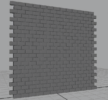
Now that's a wall! With this, you can create a good representation of a real-world wall, with all of the imperfections, age, and interest that will make your game environment feel true and alive (Figure 1.11).
Unfortunately, no magical button exists that will spit out a perfect texture. You will need to do some work first. You'll need three kinds of textures (or maps) for your brick wall project: diffuse, normal, and specular. See the "Diffuse, Normal, and Specular Maps" sidebar for more information regarding these texture types.
You can create textures using several methods. The method I use with the most success is to generate my basic texture sources in Maya and then manipulate these sources in a 2D image program such as Adobe Photoshop to get my finished results. There are plug-ins and applications that can automatically generate texture sources, but I find them to be either too slow or too imprecise. This is all a matter of preference, of course, and with these tools your mileage may vary. Although most methods have their valid uses, for this book, you'll be following this method.
You'll now focus on each of your three texture sources, one at a time. Once you have your finished texture maps, you'll apply them to a low-poly mesh that will represent a finished wall in a game.
You'll first create a simple source for your wall's diffuse map. This source will act as a starting point for your final diffuse texture later.
Select all of your bricks (not selecting the background cube) and select Mesh → Combine. This will combine all of the bricks into one object. Name your combined brick object
Hi_Bricks. You can also name the background cube simplyBackground.Note
Now is a good time to perform some housekeeping on your scene by deleting the unnecessary history that your objects may have. To do this, simply select everything and select Edit → Delete By Type → History. I tend to make a Shelf shortcut for this common command by holding down Ctrl+Shift and selecting it from the previously mentioned menu path. It will then appear on your Shelf for easier access.
With Hi_Bricks selected, hold down the right mouse button and, from the marking menu that appears, choose Assign New Material → Lambert. The Attribute Editor for your new material should automatically open. If not, open the Attribute Editor by pressing Ctrl+A, and then click the Lambert2 tab near the top-right of the window that opens to access the new Lambert material's attributes.
With the attributes of Lambert2 displayed, change the color to white by simply dragging the Color attribute's slider all the way to the right. Feel free to rename this Lambert to something more appropriate (perhaps
brickColor?) by typing a new name in the text field near the top of the Attribute Editor, next to where it reads "Lambert."Select the Background cube and repeat step 2, assigning a new Lambert material. This time, change this Lambert's color to black by dragging the Color attribute's slider all the way to the left. Again, you can rename this Lambert material to something more appropriate if you like, such as
mortarColor.In the Side View, select Create → Polygon Primitives → Plane. Drag from the top-left corner to the bottom-right corner of the brick wall. A new plane is created.
With the plane selected, now select its creation options under the Inputs section of the Channel Box on the right and set the following:
Width
100
Height
100
Subdivisions Width
1
Subdivisions Height
1
Create Uvs
Normalization Off
Rename the plane
Low_Poly_Wall. Center it on the high resolution wall geometry and have it "set" on the grid just as the wall does.By turning off UV Normalization, you've prevented problems in the future. Specifically, with Normalization on, the plane doesn't use 100 percent of the UV space available for its textures. For tiling textures, it's important to use the entire UV space. If you don't, you'll have large gaps in your textures when they tile.
Note
UVs are texture coordinates. Think of it this way—as you probably know, 3D geometric space is represented by three coordinate directions, width, height, and depth, which are represented as X, Y, and Z. Texture space in Maya is represented with two coordinate directions, width and height, which are represented as U and V. That's how you get the common shorthand term: UVs.
Push the Low_Poly_Wall plane back so that it is embedded into the brick wall you have created so far. You'll want to move it into the wall so that you do not see the plane between the bricks anymore. Deselect everything.
On the status line in the upper-left corner's drop-down box, switch your menu set from Polygons to Rendering. There are lots of useful new menu commands here, but there's only one that you're interested in right now.
Select Lighting/Shading → Transfer Maps. The Transfer Maps dialog box will open. There are lots of settings and options in here that you will be making extensive use of throughout this book. Move the window to the side so you can easily see it and your scene.
Select the Low_Poly_Wall (use the Outliner if you have difficulty selecting it while it is inside the wall). In the Transfer Maps window, under the Target Meshes section, click the Add Selected button. The Low_Poly_Wall will be added to the Target Meshes section.
Select the Hi_Bricks and Background objects that make up the high-resolution mesh. Under the Source Meshes section, click the Add Selected button. Likewise, the selected high-res models are added to the Source Meshes section.
Under the Output Maps section, click once on the Diffuse button, indicated by the four-color circle in the row of icons. Beneath it, you should see a Diffuse color map check box appear, along with several settings.
In these settings, click the folder icon next to the Diffuse color map setting and browse to a good location to save your generated source textures. Save it as a Targa (tga) file and call it
brickwall_diffuse_source.tga.Before moving on, make sure the check box next to the Diffuse color map section title is checked if it isn't already.
Under Connect Output Maps, uncheck Connect maps to shader if it isn't already.
Lastly, under the Maya Common Output section, make sure the following are set:
Map Width
1024
Map Height
1024
Keep Aspect Ratio
Yes
Sampling Quality
Medium (4×4)
This will generate a 1024×1024 texture with a medium quality. You don't need anything to be super high quality at this stage. The higher the quality you set, the longer it takes to finish generating your textures.
Back up at the top, under Target Meshes, change the Display drop-down menu to Both and slide the Search Envelope (%) slider to the right until the red plane in your scene extends in front of the bricks. In my scene, I extended it by about 3.0 percent.
The Search Envelope tells Maya how far out from your plane's original position you want it to look to generate your texture. You don't want it to look too far, so that you save processing time, especially in cases where there is other geometry in the scene that could interfere with the textures being generated.
Click the Bake button.

This may take a few minutes, but when done, you should have a black-and-white image of your brick wall, like in Figure 1.12.
Black and white is OK, but it's a bit boring. Just to help out a little, you'll add some color to your source image before moving on.
Note
For this project and all other projects in this book, I'll be using Adobe Photoshop for textures. Other 2D image programs, such as GIMP (GNU Image Manipulation Program) or Corel Painter are also viable but will obviously have their own commands and shortcuts to do the same tasks I'll be doing in this book. They should be similar enough, though, that you won't have too much trouble following along.
In Photoshop, with your
brickwall_diffuse_source.tgaopen, select the entire image (Ctrl+A) and copy it (Ctrl+C).Open the Channels tab (next to the Layers tab). Click the Alpha 1 channel to select it and paste (Ctrl+V). You now have a copy of your black-and-white brick image in your Alpha channel.
Deselect all (Ctrl+D). Click the RGB channel to get out of the Alpha channel.
Ctrl+click the Alpha 1 thumbnail next to its channel to load that channel as your selection. This means that you've selected the white area of the bricks and not the black area of the mortar between the bricks. Return to the Layers tab without deselecting.
At the bottom of the Layer palette, click the New Layer button to create a new layer above your original layer. Double-click it to rename it
Bricks.Change your foreground color to white and fill your selection with white by pressing Alt+Delete. Deselect all.
Select the Background layer (your original layer) and fill it with black. Now, you've recreated your original image, but with your two layers separated you can manipulate the bricks and the mortar separately! Before continuing, select the Bricks layer to make it the active layer.
Click the New Layer button to make an empty layer above the Bricks layer and fill this layer with a red color. Rename this layer
Color.Hold down the Alt key on your keyboard and put your cursor between the Bricks layer and the new Color layer. Your cursor should change to what looks like two intersecting circles. Click here and the Color layer will indent above the Bricks layer.
By nesting the Color layer over your Bricks layer, the color will appear only where your bricks layer is visible, allowing the black background layer to show through. You'll be doing something similar to this later when you start making the final textures for your brick wall.
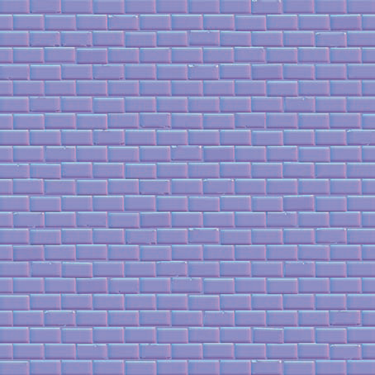
Save this file as brickwall_diffuse.tga and a copy of the Photoshop file as brickwall_diffuse_master.psd. If you like, go ahead and apply brickwall_diffuse.tga to your Low_Poly_Wall plane to see what it looks like. It should look similar to Figure 1.13.
The next step will be to generate a starting point for your normal map. You'll again use the Transfer Maps tool in Maya. I'll also show you an alternative method that can be useful for certain situations. But first, you'll get a little organized.
You'll create a couple of layers to make things a bit more manageable, so if the Layer Editor isn't already visible, toggle its button above the Channel Box to enable it.
The three available Channel Box displays show the Channel Box, the Layer Editor, or both the Channel Box and Layer Editor together. Choose either the second or third option to toggle the Layer Editor as useable.
Click the Create a New Layer button twice. Double-click Layer 1 and in the dialog box that opens, rename it
high. Do the same for Layer 2, renaming itlow.Select both the Background and Hi_Bricks objects, right-click and hold on the high layer, and from the menu that appears, choose Add Selected Objects.
Select the Low_Poly_Wall object, RMB and hold on the low layer and choose Add Selected Objects.
Now, you can toggle the visibility of the two layers to make it easier to select what you need. With that done, you can focus on generating your normal map source. It's done in much the same way as the diffuse map source was generated, with the Transfer Maps set of commands.
Hide the high layer so only the Low_Poly_Wall is visible. Select it and select Lighting/Shading → Transfer Maps. By having selected the wall before opening the Transfer Maps window, it automatically loaded it into the Target Meshes section.
Unhide the high layer, select the Hi_Bricks and Background objects and, under Source Meshes, click the Add Selected button.
Under Output Maps, if the Diffuse color map section is still there, you can click the Remove Map button next to it to remove it from the output list, or simply uncheck it to deactivate it.
Click the Normal icon to add a Normal map check box. Within the Normal map section, make the following changes (if they aren't already made by default): set File Format to Targa (tga), and set Map Space to Tangent Space.
Note
Object-space normals can be used in limited circumstances, but they aren't used nearly as often as Tangent-space normals in most games. Object-space normals can be used (if the game engine supports them) on objects that are not going to be rotated, deformed, animated, and so on. Otherwise, the shading would change and make it incorrect to the viewer. Tangent-space normals are more flexible, allowing limitless deformation and rotation.
You'll want to use all the same settings that you did for your diffuse map in the Transfer Maps options.
Click the folder icon next to the Normal map option and browse to the folder where you saved your diffuse textures. Name it
brickwall_normal_source.tga.Click the Bake button and wait as the normal map gets generated and saved. This can take a while, depending on the complexity of your objects. For this brick wall, though, it shouldn't take too long.
Open Photoshop and open
brickwall_normal_source.tga. In the Layer palette, located in the middle of the buttons that run along the bottom, click the Create New Fill or Adjustment Layer button and choose Brightness/Contrast from the list that appears.Set Brightness to +10 and Contrast to +30. Then click OK.
Save the result as
brickwall_normal.tga. Also save a Photoshop copy asbrickwall_normal_master.psd.
This helps your normal map "pop" a little, getting rid of some of the washed-out look that the generating process sometimes can give you. Figure 1.14 shows my resulting normal map.
You can go ahead and assign the normal map to your material's bump map attribute to see what it looks like. You would have to turn on High Quality Rendering mode and maybe create a light source to get the full effect (as mentioned earlier).
What you just did is the process of creating a normal map source that you'll use for 99 percent of every model you make in your career. However, this brick wall project is presenting you with that exceptional 1 percent scenario—you are creating a texture using a flat, square plane of modeled source details. This allows you to use the light array method. This alternative method works only with these sorts of projects, but it can give you quicker, more accurate results.
Hide your low layer and unhide the high layer. You can turn off High Quality Rendering mode if you haven't done so already.
Select the Background and Hi_Bricks models and apply a new Lambert material by right-clicking and choosing Assign New Material → Lambert from the marking menu that appears.
In this Lambert material's attributes, change the Color to white and slide the Diffuse attribute all the way up to 1.0. You can then close the Attribute Editor.
Select Create → Lights → Directional Light. Scale it up larger if needed to make it easier to see and manage. Facing the brick wall, move the light to the right and rotate it 180 degrees in the X direction so that it is pointing to the left, in my case, along the positive z-axis.
In the Persp viewport menus, select Lighting → Use Selected Lights. In the following steps, only the selected light will be active in the scene. As you can see right now, a white light is currently hitting the wall from the right side.
With the light still selected, hit Ctrl+A to open its Attributes. Click the white box next to the Color attribute to open the Color Chooser dialog box.
Under the Sliders section of the Color Chooser, change the drop-down menu from using HSV (which stand for Hue, Saturation, and Value) values to instead use RGB (which stands for Red, Green, and Blue) values. Also make sure that the drop-down menu on the right is set to 0 to 1.
For the R, G, and B sliders, input the following:
R 1.0,G 0,B 0. This makes your light 100 percent red. Click Accept to close the Color Chooser and minimize the Attribute Editor. In the scene, you now have a red light coming from the right side.Duplicate (Ctrl+D) the red light and move it to the left of the brick wall and rotate it 180 degrees to face the right, along the negative z-axis, pointing back toward the first light. Open the second light's Attributes and, keeping it red, change the Intensity value from 1.0 to −1.0.
Select both lights and you can see you have the red light on the right and the negative red light on the left (displaying as black). Duplicate the first light and rotate it 90 degrees to point it down and move it above the brick wall. Change its color from 100 percent Red (1, 0, 0) to 100 percent Green (0, 1, 0). Make sure this light's intensity is a positive 1.0.
Duplicate this green light, rotate it 180 degrees to point up, and move it below the brick wall. Make its Intensity value −1.0.
Duplicate the first light once more and rotate it 90 degrees in the Z direction to point this light at the front of the brick wall. Move it to a position in front of the wall. Change its color to 100 percent Blue (0, 0, 1) and 1.0 Intensity.
You're almost done with the lighting setup. Select Create → Lights → Ambient Light. Move the new ambient light in front of the brick wall as well. Set Ambient Shade to 0, and make these changes to Color:
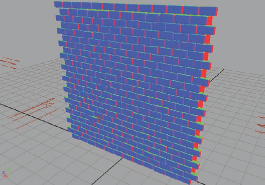
ColorR0.5G0.5B0.5In the viewport menus, select Lighting → Use All Lights (or press the 7 shortcut key) and your resulting lighting should look something like Figure 1.15.
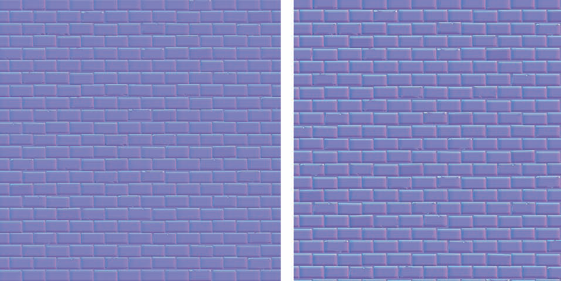
So, what was the point of all that? If you go to your Side View camera angle and render an image, you get what looks like a complete normal map! Check out the side-by-side comparison in Figure 1.16. The normal map on the left was generated using the Transfer Maps method while the one on the right was rendered with the light array method. The one on the right is just a bit crisper and more vibrant. It's up to you to decide which method you prefer, but remember, this alternative only works when dealing with a block of detail geometry that can be rendered from one direction like this.
It doesn't have to be that limited, though. For example, you could render a normal map of a grid formation and add it to another normal map in Photoshop. This way, you can add details with different models. I'll go over how to combine normal map details together later in this chapter in the "Mixing Normals" section. Be creative and you can come up with all sorts of uses for both normal map generating methods.
The last source texture you'll generate is known as an Ambient Occlusion map, or an AO map. It will be used to help create your final diffuse map. Once again you'll use the Transfer Maps commands to do this. An ambient occlusion is used as an adjustment layer. It's not a map that you'll use all on its own, but rather it's an image that you'll add to your final diffuse map to give additional details. In the next section, I'll go over that process. But for now, just worry about actually making it.
Select the Low_Poly_Wall object and open the Transfer Maps window, automatically adding it to the Target Meshes section.
Add the Background and Hi_Bricks objects to the Source Meshes section as you did earlier in the chapter.
Click the Ambient icon under the Output Maps section to add an ambient occlusion map check box with options. Deselect the normal map check box if it's still checked from a previous step. Here, you want to keep the default settings. Click the folder icon to browse to your texture locations and name the ambient occlusion map
brickwall_AO.tga.Unlike the diffuse map and normal map, which used the Maya Common Output settings, the ambient occlusion will use the mental ray Common Output settings. Here, set the following:
Map Width
1024
Map Height
1024
Keep Aspect Ratio
Yes
UV Range
Normal (0 to 1)
Otherwise, keep default settings. All you did here was make certain the resulting texture will be 1024×1024, just like your previous generated textures.
Note
To generate an ambient occlusion map, make sure you have mental ray turned on. To do this, select Window → Settings/Preferences → Plug-in Manager. In the list of available plug-ins, check the Loaded and Auto load check boxes next to the
Mayatomr.mllplug-in. All of the mental ray options should now be available.Click Bake. This can take a few minutes. Eventually, you should have something like what you see in Figure 1.17.

You're now ready to create your final textures. Texture creation is one of the most important steps in any game asset's pipeline. You can have a fantastic 3D model, but if the texture isn't good, the model won't look good. On the flip side, even a mediocre 3D model can look amazing with a great texture!
Texture creation is also a very experimental step in an asset's pipeline. If you're following along with me on the DVD video supplement, you may notice I try a few things before settling on a result I like. Here in this written instruction, I'll be showing you the steps I decide to use for my final textures.
Note
Browse on the DVD to the Brick Wall project and open
Brickwall_Start.psdin Photoshop. In this file, I have the generated normal map in its own Normal folder set to invisible. In the Diffuse folder, I have the previously generated AO map as well as the white and black masking layers from thebrickwall_diffuse_master.psdfile. This will be your starting point.Note
It's a good idea to keep a library of texture resources handy. Rock, wood, foliage, brick, skin, metal—the more photographic reference material and source material you have, the more flexibility you'll have in your textures. One good online resource for these kinds of source files is
www.cgtextures.com.Open a good concrete source image from
www.cgtextures.comor from your own personal texture source library. The one I've chosen can be found on the DVD asConcreteBare0145_1_M.jpg. Drag it into your brick wall file in Photoshop to add it as its own layer above the black background layer near the bottom of the layer stack. Double-click the new concrete layer's name and rename itMortar.Double-click the AO layer. This opens the Layer Style window where you can do all sorts of layer adjustments. Right now, you just want to adjust the AO layer's Blend Mode. There are lots of different blending modes to choose from and you should take some time to look into them to see how they react with different color values and such in future projects.
From the drop-down list, choose the Multiply blend mode. This makes all white pixels become transparent and all black pixels remain opaque.
Select the Mortar layer and create a new adjustment layer (from the button at the bottom of the layer window); choose Brightness/Contrast and set Brightness to
+23and Contrast to+40.This gave your mortar layer a bit more contrast and brightness without adjusting the layer itself. Only layers below an adjustment layer are affected by them.
Drag the Mortar layer to the Create a New Layer button at the bottom right of the layer window to create a copy of the Mortar layer. Rename this layer
Brickand drag it to be above the Brick_Mask layer.Hold the Alt key and click in between the Brick and Brick_Mask layers to nest the Brick layer in the mask layer. This way, the mortar below the brick layers will show.
With the Brick layer selected, create a new Brightness/Contrast adjustment layer and set Brightness to –
35and Contrast to+35.For my concrete sample, this will increase the contrast while darkening the brighter areas of the texture to serve as a good base for my brick.
If you're using the same concrete texture source that I am, select the Brick layer and click Ctrl+T to turn on Free Transform mode. You may need to zoom out (Ctrl+-) a bit to see the full extents of the Free Transform handles. Pull these in to be flush with the sides of your texture. Press Enter to finalize the adjustment.
With the Brick layer still selected, create another adjustment layer. This time choose Hue/Saturation. Input these values: Hue –
72, Saturation –37. This will shift the brick layer's color toward the cool side of the spectrum, adding a more blue/purplish hue.Hold the Alt key and click between the Brick layer and the Hue/Saturation adjustment layer. Do the same between the Hue/Saturation and Brightness/Contrast adjustment layer. This nests both adjustment layers within the Brick_Mask layer, keeping the Mortar layer beneath unaffected by the adjustment layer's effects.
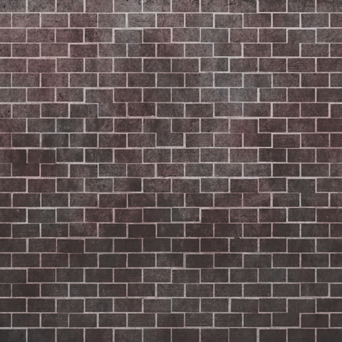
At this point, you should have something like Figure 1.18.
Create a new layer above the Brightness/Contrast adjustment layer and Alt-click between them to nest this new layer within the same group as the Brick_Mask. Rename this layer
Color.Fill (Alt+Delete) this layer with a dark red color. I chose a color with the RGB Values as follows: R
102, G54, B54.Change the Color layer's Blend Mode to Overlay. This mixes the Red layer's color in with the color of the layers below it, giving you a good base red color for what will be a red-brick wall.
Take the Color layer's Opacity down to about 90 percent to lessen its impact a tad.
In real life, hardly anything is just one hue. Things usually have some kind of color variation, splotches of dust or grime, scratches, and so on. You'll add a layer of that to your brick texture.
Get a new concrete-like source image, one with more splotches of dark and light hues. It doesn't really matter what color it is. The one I found can be located on the DVD called
br013.jpg. Drag it into your file and nest the new layer below the Color layer, keeping the group of layers nested with the Brick_Mask layer as before. Rename the layerColor Variation.Change the Color Variation layer's Blend Mode to Overlay and take its Opacity down to about 55 percent.
This new color variation layer overpowers the general look of the brick a little too much, so you'll try something new. Double-click the Color Variation layer to open the Layer Style window. Toward the bottom are two sliders—one labeled This Layer and the other labeled Underlying Layer.
Using the Underlying Layer slider, slide the black handle about halfway to the right. You should notice that the Color Variation layer starts to "melt" away, showing more of the layers beneath it. See Figure 1.19 for an illustration of what I mean.
You can continue to adjust the sliders to get a look that you are satisfied with. But to be honest, no matter how I adjust these sliders, they tend to result in a very grainy, speckled look. In a game especially, that kind of thing can lead to strange mosaic patterns developing when a grainy texture is viewed from a distance. Let's smooth the blend transition.
Looking back at the Underlying Layer slider, hold down the Alt key and click and drag the black handle to the left. You'll see the handle actually split in half, creating a smoothing effect on the blending! Take a look at Figure 1.20 to see the results of this kind of adjustment. It's subtle, but it helps prevent speckling and graininess.
You'll add a gradient to the texture so that it is darker toward the base of the brick wall, representing years of dirt and grime that accumulates at street level. Create a new layer and place it above the Color layer. Don't worry about nesting this one. Rename it
Grime.Click the Gradient Tool (G) and you'll have a new set of options along the top of Photoshop's interface, giving you several different gradient types to choose from. Make sure Linear Gradient is the active option.
Hold the Shift key and click and drag upward, making a gradient that runs upward black-to-white. Move the layer down so that the blackness only covers about 20 percent of the lower side of the texture.
Change the Grime layer's Blending Mode to Multiply and lower the Opacity to about 35 percent.
Select the topmost AO layer. With the Rectangular Marquee Tool (M), select an area around an individual brick. Create a new Brightness/Contrast adjustment layer. With the brick selected, it automatically loaded the selection into the adjustment layer's mask so only the selected area is being affected. Set Brightness to –
26and Contrast to –10.Continue to select random, individual bricks and within the mask fill your selection with white to add it to the adjustment layer's mask. Do about 10 bricks.
Do it again, selecting an individual brick and creating a new Brightness/Contrast adjustment layer. This time, set Brightness to
+26and Contrast to+10. Add about ten random bricks to this adjustment layer's mask.These last few steps added some random discoloration throughout the wall, giving much more of a worn, aged look and feeling, which is always important for such environments. At this point, your Diffuse texture is nearly done. You can do one last thing to finalize it and make it ready for your wall.
Select all (Ctrl+A) and press Ctrl+Shift+C to Copy Merged. This command copies every visible layer, not just the selected layer. Press Ctrl+V to paste, making a new layer. Move the layer to the top of the stack if it's not already there and name it
Final.With the Final layer selected, select Filter → Sharpen → Unsharp Mask. Make the following adjustments:
Amount
50%
Radius
1.5 pixels
Threshold
5 levels
The Unsharp Mask filter will help sharpen up the details of the texture, allowing them to stand out, and remove any unwanted smudging.
Save the .psd file so you can make any future adjustments that may be necessary and save it as
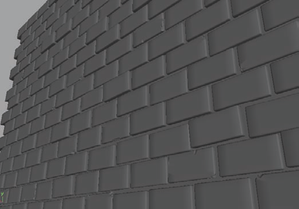
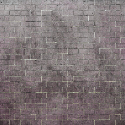
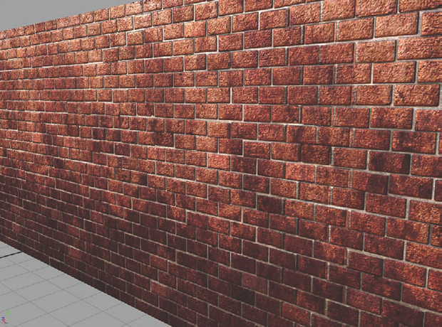
Brickwall_Diffuse.tga. Apply the new texture to your wall to see how it looks so far (Figure 1.21).


Now, you will take your Normal map source and modify and improve it to create a final normal map texture you can use for your wall. As mentioned, in the Brickwall_Start.psd file, I've provided you with a Normal folder that includes the normal map images you would have created thus far. You are free to replace these with the ones you have generated yourself if you prefer.
With the source that you generated, you already have the basic forms that make up the individual bricks and the grooves in between them for the mortar. However, other than those large details, there aren't any smaller details in the normal map source, such as scratches, granularity, grooves, and so on. These small details are what you will add now.
First, you'll take a source image from your diffuse texture layers. Hide the Final layer as well as the AO layers and Brightness/Contrast layers until all that remains is the red-rock brick and white mortar. Click Ctrl+Shift+C to Copy Merged.
Open the Normal folder and select the Brightness/Contrast layer here. Ctrl+V to paste the copied brick layer. Rename this layer
BrickNormal.Select Image → Adjustments → Desaturate to desaturate the brick image, removing the color information and leaving a grayscale version.
Back under the Diffuse folder, Ctrl+click the Brick_Mask layer to load it as a selection. You'll notice that you have the bricks selected and not the mortar.
Select the Select → Inverse menu to invert the selection. Now, you're selecting the mortar pixels instead of the bricks. If it's not still selected, select the BrickNormal layer back in the Normal folder.
Select Image → Adjustments → Levels to open the Levels dialog box. Lower the Output Levels values near the bottom from the default of 0, 255 to
0,49to make the mortar area black rather than white.When converting a grayscale image into a normal map, the range from white to black plays an important role in determining height. Where pixels are dark, a normal map will be indented or recessed. Where pixels are light, a normal map will be bumped up or raised. So, if you wanted to accurately represent a brick wall's depth in your grayscale image, you needed to make the mortar much darker. Otherwise, the mortar would look like it was sticking far out of the wall.
Now that you have your grayscale image more accurately represented, you can convert it from height information into normal information for use in a normal map. Several widely used Photoshop plug-ins exist that can do this for you. I like to use xNormal, which you can download for free at
www.xnormal.net/Downloads.aspx. Another popular one is the nVidia Normal Map filter (http://developer.nvidia.com/object/photoshop_dds_plugins.html). For this book's instruction, I'll be using xNormal commands, because I like the quality of its results better than most other alternatives.Now you'll convert your grayscale height map into a normal map. With the BrickNormal layer still selected, select Filter → xNormal → Height2Normals. In the dialog box that opens, the default is typically fine, but feel free to play with the settings to get the results you are after. Press Continue; your grayscale image will be converted into a normal map.
Select and drag the BrickNormal layer to the New Layer button to effectively make a duplicate layer above the original.
Rename the new layer
NormalAdd. Rename the BrickNormal layerNormalSubtract. So, now you have the NormalAdd layer above the NormalSubtract layer in the Layer palette.
The next steps will mix the normalized details of your new layers with the Normal_Source layer by using the NormalAdd layer to remove negative values and the NormalSubtract layer to remove the positive values. It sounds complicated, but as you go through it, you'll pick up on what each step is doing.
Select the NormalAdd layer and select Image → Levels. Make the following changes, changing Channel first:
In the NormalAdd layer, you've removed all negative values, leaving only the positive values. You'll work on the NormalSubtract layer next. You can hide the NormalAdd layer by clicking the eyeball icon next to it in the Layer palette.
Select the NormalSubtract layer and select Image → Levels. Make the following changes, changing Channel first:
CHANNEL
RED
GREEN
Input Levels
0, 1.00, 127
0, 1.00, 127
Output Levels
0, 127
0, 127
Leave the Blue channel as it is.
Similar to removing the negative values from the NormalAdd layer, here you've removed the positive values from the NormalSubtract layer. Next, you're going to convert these two layers into offsetting positive and negative values which can then be blended with the Normal_Source layer.
With the NormalSubtract layer still active, select Image → Adjustments → Channel Mixer. Change the Output Channel to Red and set Red to –
100and Constant to50.Change the Output Channel to Green and set Green to –
100and Constant to50.Change the Output Channel to Blue and set Blue to
−100and Constant to100. Click OK.Unhide and select the NormalAdd layer. Open the Channel Mixer once more, set Output Channel to Red, and set Constant to
−50.Change the Output Channel to Green and make its Constant value
−50as well. Make no changes to the Blue channel.The NormalAdd layer now contains offsetting positive values while the NormalSubtract layer contains offsetting negative values. You'll adjust their Blending Mode to finally mix the values with the original Normal_Source layer.
Select the NormalAdd layer if it isn't selected already and change its Blending Mode setting to Linear Dodge. The linear dodge blending mode takes the base colors and brightens them with the blend colors, enhancing their affect on the base normal information rather than overpowering it.
Select the NormalSubtract layer and change its Blending Mode to Difference. The difference blending mode is the function that actually causes the color subtraction to take place.
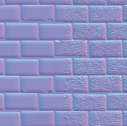
Voilà! The normals are mixed (Figure 1.22)! You may want to adjust the intensity of your new normal information by decreasing the opacity of both Add and Subtract layers. I typically might reduce them both by 50 percent, but in this particular case, leaving them at their full intensity looks pretty good. Make sure that you make any changes to both layers to keep their offsetting values in sync.
Save your Photoshop file and save your normal map as brickwall_normal.tga. Feel free to take a look at your handiwork in Maya if you like. Remember that High Quality Rendering mode must be active to view a normal map in Maya in real time.
The final step in your texture creation process for this project is to create a specular map. Unlike the normal map or diffuse map, you don't need to generate anything from Maya to have a source. Instead, you'll be using Photoshop to make one from scratch.
Specular maps can be grayscale images, where black represents areas with no specular and white represent areas with maximum specular values. They can also include color information. If they do have color, the color is seen in the hue of the specular shine on the model.
Realistically, only metallic objects should have colored specular maps. However, including some color in a specular map on nonmetallic objects can help pump up their visual presentation, which can add a bit of pizzazz to the look of an object. It'd really be up to the art direction of each particular project and how realistic you were trying to be. In general, the main concern is that your art looks good. Looking good usually trumps looking realistic. After all, realism can be boring!
So let's get started!
Note
Make sure you don't confuse reflection with specularity. If my plastic spoon is shiny and reflective enough, I can see myself in it and see that my reflected image is obviously in full color. But the spoon's specular highlights are themselves always white. A metallic surface's colored specularity will reflect my own coloring as well as the coloring of its surface, tinting my reflection a different color.
First you'll take a source image from your diffuse texture layers, just as you did when you began your final normal map. Hide the Normal folder. Then, hide the Final layer as well as the AO layers and Brightness/Contrast layers until all that remains is the red brick and white mortar. Press Ctrl+Shift+C to Copy Merged.
Select the Final layer and press Ctrl+V to paste the copied brick layer. Rename this layer
Spec_Base. Move this layer so that it's between the Diffuse or Normal folders. You're going to make a new folder for it.With the Spec_Base layer selected, select Layer → New → Group From Layers. In the dialog box that opens, name the new folder
Specular. You should now have a new folder named Specular between the Normal and Diffuse folders. Within the Specular folder is your Spec_Base layer.Because you're dealing with a brick wall, your final specular map will be mostly grayscale. As mentioned previously, it's primarily metallic objects that will have a colored specularity. However, because of what brick is made of, there are tiny rocks and metallic particles within it. To convey this, you'll add just a hint of color to your specular map.
Select Image → Adjustments → Desaturate to desaturate the brick image, removing the color information and leaving a grayscale version.
Create a Brightness/Contrast adjustment layer and set Brightness to
−42and Contrast to−42. This will darken the image. If you left the whitest pixels as bright as they were, your specular would be incredibly bright and hot. You'll want to be a little more subtle.Create a Levels adjustment layer and make the following changes:
Input Levels
0, 0.77, 162
Output Levels
0, 186
Above the two adjustment layers you've made, create a New Layer and name it
Color.Click the Foreground color swatch on the Tools palette (usually on the left side of the Photoshop interface) to bring up the Color Picker. Select a deep red color and click OK.
Click the Background color swatch and choose white and click OK.
With the new Color layer selected, select Filter → Render → Clouds. This command will fill the image with a cloudy pattern using the two colors you've selected.
Change the Color layer's Blending Mode to Soft Light, adding a tint of the red color to the specular map.
Lower the Color layer's Opacity to about 50 percent to reduce the impact of the coloring.
Save your Photoshop file and save your specular map as
Brickwall_specular.tga.
In Figure 1.23, you can see the final specular map. You can view the end result in Maya by assigning the specular map to the Specular Color attribute of a Blinn material on your wall. To see a more accurate view of the specular map in real time, you'll need High Quality Rendering mode turned on.
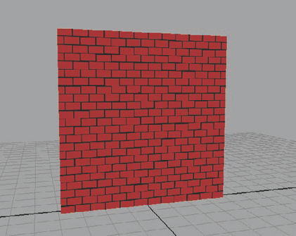
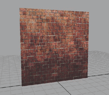
With the final diffuse, normal, and specular maps completed and applied, your brick wall is complete (Figure 1.24)! You can apply the textures you've created to a modular wall mesh system to create an interlocking series of walls in a final game world. And you can create textures for ceilings and floors in the same fashion as you have for this wall. In the next project, you'll get off the walls and start making some scenery.
It may seem as if I've introduced an enormous amount of new information to you in just this first chapter. Don't be too concerned if you feel a case of information overload. Such a feeling is common when starting a new job in the game industry as well! All it takes is time and practice to develop a familiarity with each of these methods.
The concepts introduced in this first chapter will be gone over again in later chapters to help give each task additional information and context, and to allow you, the artist, more practice in using them as well as learning new concepts that are introduced as the book progresses.