When creating any sort of exteriors, rural and urban alike, you'll usually have some sort of foliage. Trees, vines, grass, flowers, weeds, corn stalks, lily pads, fungi, river reeds, seaweed, etc. The list can stretch on potentially forever. Not to mention the possibility of completely fictional plant life that can be created for fantasy or science-fiction games. But even with the current game consoles and high-powered PCs, there are still concessions that must be made to realize those details in any lush digital environment.
Practically every game requires some kind of plant life. For example, Rockstar Games' Grand Theft Auto IV takes place in an intricately detailed metropolis, filled with highways, streets, overpasses, sidewalks, skyscrapers, warehouses—in other words, complete urban sprawl. Yet there are trees, potted plants, grass, and other types of realistic foliage scattered around in parks and gardens, flower beds, and front lawns. Another example is Blizzard's World of Warcraft. Each area of this massive, online role-playing game is covered in unique types of trees and plants, a large portion of which are complete fantasy. Even an arena-based sports game like Electronic Arts' Madden NFL '09 has trees and bushes lining the exteriors and interiors of several stadiums, not to mention the grass and turf football fields themselves.
But all of these different game environments share one particular detail in common: opacity maps. In Chapter 1, "Walls, Floors, and Ceilings," you learned about the three major texture types—diffuse maps, specular maps, and normal maps. Opacity maps are a fourth texture type, and you'll learn how to use them in this chapter. Opacity maps, as you may gather from the name, control the opacity (or transparency) of a model. And if there's any type of environment prop that heavily relies on opacity maps in games, it's foliage.
Think of all those leaves! Each and every one of them. If you modeled a tree with every single leaf in place, how many polygons do you think that would take? For one tree? What about a dozen trees? Or a hundred? And then let's say you want them to sway in the breeze. Imagine a game like World of Warcraft, for instance, that has a forested area. If every single leaf and branch were modeled and present, the amount of calculations and animations involved in such a simple thing as tree branches swaying with the breeze would be staggering, never mind trying to have an actual game running in there somewhere. Frame rates would chug to a crawl, and the game would be completely unplayable.
So, what's a tree-loving game artist to do? That's where opacity maps come in. Using different sized sheets of geometry and a well-crafted opacity map, you can create the illusion of heavy details (like thousands of leaves). In the first project of this chapter, you'll come to a better understanding of how you can create such foliage models and opacity maps.
Imagine an ivy vine crawling up a tree or a swath of ivy covering an old church and you'll realize ivy is a great plant to start with when learning how to create foliage. Ivy is almost completely made up of leaves, with a few vines thrown in for structural stability's sake. Taking a look around my neighborhood, I came upon several different examples of ivy that you can use as inspiration in this project (Figure 2.1).
Note
Before starting, make sure you set your project to your project directory by going to File → Project → Set.
Note
Browse on the DVD to Projects → Chapter2→ Ivy and open Ivy01_Start.ma. This file contains a preset scene to begin creating the ivy.
In the Side view, you can see the reference image of an ivy leaf in full profile. Start by going to Mesh → Create Polygon Tool.
Using this tool, begin placing points along the profile of the leaf, tracing its image, starting from the base of the leaf (where it would meet a stem) and ending halfway around the leaf at its tip. Press Enter to finalize the tool's action.
With half of the leaf filled in, select Mesh → Mirror Geometry → Options. Make sure that the Mirror Direction is set to +Z (or whatever direction is applicable to your scene, if you aren't following along exactly), and that Merge With the Original and Merge Vertices are both selected. The half of leaf you have created so far should now be mirrored and connected on its opposite side.
If the tip or the base of the leaf isn't merged together, select the two vertices at these points and select Edit Polygons → Merge to merge them together.
After merging the two sides, select the edge that runs down the center and delete it.
Back in the Side view, you can tweak the vertices of the new side of the leaf to more closely match the image reference you have. If you need to add vertices, you can use the Split Polygon tool found under the Edit Mesh menu. With the tool active, simply click once on an edge where you want a new vertex and press Enter. At this point, you should have something similar to Figure 2.2.
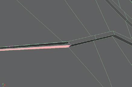
Once you have your leaf profile the way you like, select the face that makes up the entire leaf and select Edit Mesh → Extrude. Pull out the extrusion a small amount to give the leaf some thickness.
Select the front face again and select Edit Mesh → Bevel. Adjust the Offset to be about 0.32. You can delete the face on the back of the leaf.
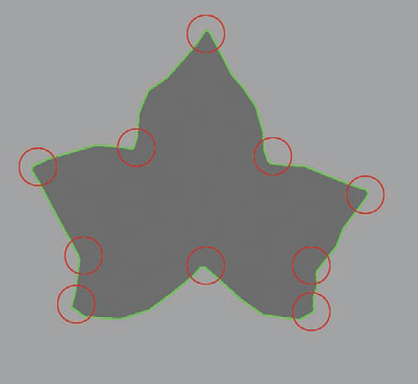
Select the edge loops that run along the tips of the leaf's pointy ends and the indentions between leaf fronds (as indicated in Figure 2.3) and apply a new Bevel. Adjust this bevel's Offset to be around 0.34.


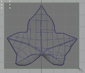
The next step is to add detail by cutting in geometry to represent the details that make up the veins of the leaf. You'll do this primarily with the Split Polygon tool. You'll want this leaf to be able to fold later, so while you're working, you can cut in the necessary geometry for that to work as well.
Using the Split Polygon tool, start cutting in geometry in the path and shape of the leaf veins. You can also cut in geometry to help with bending later. Figure 2.4 demonstrates what I mean.
Once you are finished cutting, you can select the faces that make up the veins of the leaf, but deselect the faces that are on the very ends of the veins where they merge into the tips of the leaf. Apply an extrude command and pull the veins out slightly.
The reason for not extruding the faces at the tips of the veins is that you want the vein geometry to blend back into the main leaf mesh. You can do this easily at the ends of the veins in the next step.
Select and delete the two faces on the end of each extruded vein. Then, use Edit Mesh → Append to Polygon Tool to close the gaps between them, as portrayed in Figure 2.5. You can also reference the video supplement on the DVD for more details regarding this step.
When all of the veins are sufficiently blended, select the edges of each vein and apply a Bevel to them with an Offset of approximately 0.6.
The Select Edge Loop tool, which you can find in the Select menu, can help select the vein's edges quickly. With the tool active, simply double-click an edge, and the entire loop of edges will be added to your selection.
Now you'll bend the leaf geometry to make it not so cardboard-rigid and straight. First change your menu sets from Polygons to Animation (either through the interface or by using the F2 shortcut key). Deformers are under the Animation menu set.
With the leaf mesh selected, select Create Deformers → Lattice. You'll see a wire box appear around your leaf.
The lattice deformer simply modifies a large number of points using a cage of fewer points. This helps by making large changes to a high-resolution mesh much easier to manage.
After applying the lattice, in the Channel Box on the right, change the following settings, which are found under the Shape node named ffd1LatticeShape: S Divisions:
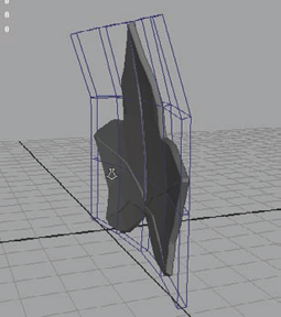
2; T Divisions:4; U Divisions:5. This gives you a better density of lattice points to work with based on the shape of the leaf.Right-click the lattice and select Lattice Point from the marking menu that appears to activate component mode and gain access to the lattice's points. Manipulate the lattice points to bend the leaf into a concave shape like in Figure 2.6.
Delete the history of the leaf (Edit → Delete by Type → History in case you have forgotten). Deleting the history removes and bakes in the changes made to the leaf by the lattice deformer (as well as all previous modeling operations, if you haven't deleted the history before now).
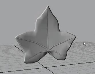
With the leaf still selected, return to the Polygons menu set (F3) and select Normals → Soften Edge. If your leaf is like mine, you'll probably notice it become covered in dark splotchy colors. This is because you need to adjust just how soft you want the leaf's normals to be.
After applying the Soften Edge command, click the polySoftEdge1 Input in the Channel Box to access the Soften Edge command's options. Change the Angle setting to about 80 degrees, or whatever value works best on your model. The goal is to remove the majority of the splotches, yet avoid obvious hard edges in your model.
Rename your model
HiLeaf.

Just as you did with the brick wall in Chapter 1, you'll follow many of the same steps to create your texture sources for the ivy leaf. You'll start by creating your low-resolution mesh to bake your texture sources to.
Note
All operations and commands in this book assume the default options are set. You may need to reset the options of tools and commands to follow along most accurately.
Create a polygon plane by going to Create → Polygon Primitives → Plane. Switch to the Side view to view the leaf head-on and left-click and drag to create the plane surrounding the area the leaf is within (Figure 2.7).
In the Perspective view, move the plane forward until it is completely in front of the leaf, with none of the leaf's parts intersecting it. In my case, I moved it forward about 8.1 units. Rename the plane
Leaf.Click the polyPlane Input options in the Channel Box and make sure that the Create UVs setting is set to Normalization Off.
You also will want to ensure that the plane's surface normal is pointing to the front, or away from the HiLeaf mesh. You can check this by selecting the Leaf plane and going to Display → Polygons → Face Normals. This will make the green line that represents the normal direction of the plane's face appear.
If it's pointing the opposite direction, select Normals → Reverse. Otherwise, click the Face Normals display command again to turn it off.
Now you're ready to start generating some texture sources. Switch your menu set from Polygons to Rendering. Then, with the Leaf plane selected, select Lighting/Shading → Transfer Maps.
In the Transfer Maps dialog box that opens, make sure that you slide your Search envelope percentage down to 0, if it's not already.
Select the HiLeaf mesh and load it into Source Meshes. You'll notice that your Leaf plane is automatically loaded into Target Meshes since it was selected when the Transfer Maps options were opened.
You can follow the same steps from Chapter 1 with regard to the settings for an Ambient Occlusion (or AO) and normal map. This time, you can choose to bake more than one map at once because you now have a better idea of how to do it. Go ahead and bake two 1024×1024 texture sources—a normal map called Leaf_Normal_source.tga and an AO map called Leaf_AO.tga.
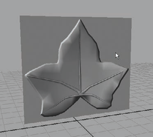
Once the baking finishes, feel free to apply your new maps to check out how they look so far. Don't forget that you need High Quality Rendering turned on for a normal map to render correctly in real time. Figure 2.8 shows how mine looks so far.
You may notice that the normal map results are a bit harsh. You could probably stand to clean that up a bit. Let's open up Photoshop.
Note
As I mentioned in Chapter 1, I'll be using Adobe Photoshop for textures. Other 2D image programs, such as GIMP or Corel Painter, are also viable but obviously will have their own commands and shortcuts to do the same tasks I'll be doing in this book. They should be similar enough, though, that you wouldn't have too much trouble following along.
The resulting normal map isn't too bad, especially the outer edges of the leaf. The irregular smoothing that I normally would attempt to fix doesn't look too bad on what should be a rather irregular shape such as a leaf. You'll just want to smooth out some of those harsh edges and angles.
In Photoshop, open your
Leaf_Normal_source.tgafile. Copy its background layer by dragging it onto the Create New Layer button at the bottom-right side of the Layer palette. Rename this copied layerSmoothDetails.With this new layer selected, select Filter → Blur → Gaussian Blur.
Adjust the Gaussian Blur settings to blur the layer by 4.5 pixels. Now the normal is definitely softened, but maybe a bit too much in most areas. Why not make the blur effect take effect only where it's needed rather than all over the whole thing?
With the SmoothDetails layer still selected, click the Add Layer Mask button on the bottom row of buttons on the Layer palette.
A layer mask is a grayscale image that is associated with a particular layer in Photoshop and acts as an opacity map: Where a layer mask is colored black, the layer is invisible; where a layer mask is colored white, the layer is visible. To apply white or black coloring to a layer mask, you have to make sure you select the mask, represented on the layer as a second preview thumbnail.
Select the layer mask and fill it with black, making it entirely invisible.
Then, with the mask still selected, start painting in white over areas that need to be softened. Make sure you are using a soft-edged brush. You want to remove unnatural hard edges that are visible in the normal map.
Note
To quickly scale your brush size larger and smaller in Photoshop, use the [ and ] keyboard shortcuts.
To soften the blend between the harder edges of the leaf's vein into the surface of the leaf, you'll change the opacity of your brush's painting strength. With the paintbrush tool still selected, at the top of the Photoshop interface, change the Opacity value from its default 100 percent to 50 percent.
First, paint over all of the veins with white using the 50 percent opacity brush. This will make the veins have a softer appearance once the normal map is applied in Maya.
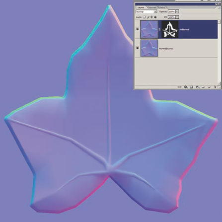
Change your color to black and paint over the ends of the veins, softly blending them into the main surface of the leaf. In Figure 2.9, you can see my final layer mask and resulting normal map.
Now that you have a good source map for both your diffuse and normal maps, you need to make the opacity map to get rid of the excess geometry that you can see surrounding the leaf. After all, you want your leaves to look like leaves, not big squares with pictures of leaves on them! Creating the opacity map for this particular project is actually quite easy.
Open the
Normal_Source.tgafile again, if you don't still have it open from the previous step.Select the Magic Wand tool (you can press W on the keyboard). With the tool active, at the top of the screen, change the Tolerance value to 0.
Select the original normal source layer (not the softened one) and click anywhere outside the leaf.
The Magic Wand tool selects pixels of similar hue values. The Tolerance setting adjusts how exact the hue value has to be for it to be selected. With the tolerance set to 0, you're telling it to select only the specific color of the pixels you click. In this case, the tool will select the entire area outside of the leaf on the normal map. This is the perfect selection with which to create your opacity map.
With the region outside the leaf selected, create a new layer and fill the selection with black. Press Ctrl+D to deselect.
Create a new layer and fill the entire layer with white. Move this new layer to be beneath the previous one. Select the black layer and press Ctrl+E to Merge Down with the white layer beneath it. The result gives you a new layer that contains a white silhouette of the leaf with a black background. This is your opacity map!
Save the resulting black and white image as
Leaf_Opacity_source.tga.
At this point, it really depends on your project's guidelines as to whether your opacity map is truly finished. Saving it as a separate file like you have done here is a common practice in certain editors and game engines, but there is another method (the one used by Maya) that many other editors use as well. This method utilizes alpha channels.
You may remember that I briefly used an alpha channel in Chapter 1 as a selection mask when creating a diffuse map source. While that is a valid way an alpha channel can be used, the way they are used in a game engine is entirely different.
Many games use alpha channels as a way of essentially "storing" an extra channel of information. For example, you can have the black and white data that represents a specular map within the alpha channel of a diffuse map that is read by the game engine—two maps in one file. The same thing can be done with opacity maps, and this is how Maya in particular uses them, so that's what you'll do here. Don't forget to consult your art director about how alpha channels are used in your own real-life projects.
It is very simple to include a texture in the alpha channel of a file. The main criterion is that it must be grayscale only. No colored maps can be included in an alpha channel since colors (Red, Green, and Blue) take up their own channels. So, although a grayscale specular map can be included in an alpha channel, a colored one could not and would have to be done a different way. But now you'll focus on putting your opacity map into your diffuse map's alpha channel.
Open your
Leaf_Opacity_source.tgafile, if it isn't already open.Select All (Ctrl+A).
Copy Merged (Ctrl+Shift+C).
Open your Leaf_AO.tga file. Next to the Layers palette tab is the Channels tab. Click it to open the Channels palette and select the alpha channel.
Paste (Ctrl+V) to paste your copied opacity map into the alpha channel.
Save your file using the Save As command (or by pressing Ctrl+Shift+S) and save your file as
Leaf _AO_Opacity.tga. This time, in the Targa Options box that opens, make certain you choose 32 bits/pixel. Click OK.
I'll take a moment to talk about the difference between 24 bits/pixel and 32 bits/pixel. If you notice in the Channels palette, you have three channels by default, not counting any alpha channel—Red, Green, and Blue (the RGB channel is simply a combination of the other three and not counted as a channel on its own). Each channel requires 8 bits/pixel. So typically, if you don't have an alpha channel, you can save your image as a 24 bits/pixel image: Three channels at 8 bits each equals 24 bits total. Therefore, if you do want an alpha channel, you'd need to add the 8 additional bits, making it 32 bits/pixel.
Make sure that, when you save a .tga file without an alpha channel, you don't save it with 32 bits/pixel because it will create an empty alpha channel for you in most game engines. This wastes texture memory, which, by the time a project is coming to its last few months, becomes a precious commodity!
Let's get back to Maya. Apply your new Leaf_AO_Opacity.tga file to your leaf plane's material's Color attribute. You should get a result like Figure 2.10. Only the leaf part of the plane is visible!
You'll finish up the textures later. For now, you'll create the rest of the ivy.
Select the leaf plane and press the Insert key on your keyboard. This toggles Edit Pivot mode. Move the plane's pivot point to about where you would expect the leaf to meet a vine—where all of the veins converge in the middle. Press Insert again to exit Edit Pivot mode.
With the pivot moved to where the leaf would meet its vine, you can more easily position and rotate the leaf when you have the vine mesh completed.
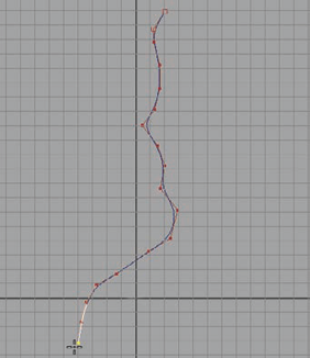
In the Side view, select Create → CV Curve Tool. By left-clicking, create a curve that will represent the path of your vine. You can see mine in Figure 2.11.
Shrink your leaf to be a correct shape next to the curve, as if the curve was the vine the leaf had grown from. I shrunk mine down about 0.2 percent from its original shape, but the amount you scale it will depend on how big your leaf originally was compared to how big your curve is.
Curve snap (hold the C key and middle mouse button, and click and drag on the curve) the leaf to the curve. Because your pivot point was moved to be at its connection point, the leaf will run along the curve at the correct position to represent the idea that it had grown from the vine.
Duplicate the leaf and position the new leaf on the vine. Rotate the leaves to point downward and to point in different directions so they aren't all uniform. Scale the leaves so that they begin larger near the top of the vine and shrink to be much smaller near the vine's tip.
Create another curve and curve snap the first point to the first curve before creating the rest of it. This way, the new curve looks like it is a branch growing off the vine.
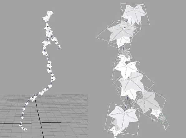
Continue placing ivy leaves on both curves. Eventually, you should have something like Figure 2.12.
Select Create → NURBS Primitives → Circle. Click and drag to draw a small circle approximately the diameter of the vine you want. Mine had a radius of about 0.75.
Under the makeNurbCircle1 Inputs in the Channel Box, change the number of Sections to 4.
Select the circle and Shift+select the main curve that makes up the long vine. Change your menu set to Surfaces. The Surfaces menu set contains menu commands that mostly relate to working with curves and NURBS surfaces. Select Surfaces → Extrude → Options.
Make the following changes:
Result position:
At path
Pivot:
Component
Output geometry:
Polygons
Type:
Quads
Tessellation method:
General
U type and V type:
Per span # of iso params
Number U and V
1
Click the Extrude button. A polygon tube should be created, running along the pathway of the curve you had drawn. Repeat the extrude step for the smaller vine's curve, creating a tube for it as well. You should have a result similar to Figure 2.13.
Take the opportunity to adjust the vines' shape by manipulating the Curve Points on your vine curves. When you're happy with the shapes, select both pieces of vine geometry and delete their history.
Go back to the Polygons menu set. Select the vertices at the tip of one of the vine meshes and select Edit Mesh → Merge To Center. This will combine and collapse the vertices together to make the end of the vine into a point. Do the same for the tip of the other vine section.
Select the row of vertices next to the tip on one of the vines and scale them in. Select the next row and scale them in slightly less. Select the next row of vertices and scale them in even less. Continue until you have tapered the ends of both vines, making them look like they are thick near the top and become thinner as the vine grows near its tip. You can make the top, or base, of the vine thicker if you need to.
At this point, your leaves may need to be repositioned to more closely match the new vine meshes you've created. Go through and position them so that they are accurately attached to the vine.

When all of the leaves are in place, your vine model is complete. Now it's time for the final texture work.
The main challenge of creating the ivy textures will be avoiding a repeating pattern. You want all of these leaves to be clumped together naturally, but there's nothing more unnatural than being able to easily recognize that every leaf looks exactly the same. Of course they're going to, but there are ways to ensure that it's not obvious. By avoiding large details that can be easily seen from a moderate distance, you can prevent this pattern recognition.
Note
Browse to the Ivy project folder on the DVD and open the Ivy_Start.psd file. This Photoshop file contains a diffuse, a normal, and an opacity folder with the base textures I have created inside.
Open a good leaf source image. The one I used is called
Leaves0051_S.jpgfromwww.cgtextures.com. It shows a nice amount of detail in the leaf's surface as well as some good vein detail that you can use. I'm going to grab the vein detail to use for my own leaf.Click the Polygonal Lasso tool and at the top of the screen, make the Feather value 5 pixels (px).
If you're following along with me, select the main vein down the center of the leaf with the lasso tool until you have the entire vein selected.
With the Move tool, click within the selected area and drag from your source image into your Photoshop file. This will drop the selected leaf vein into your file. Reposition and rescale it with the Select Transform tool to make it fit along the middle of the leaf.
Repeat these steps, selecting source pixels from the leaf image and moving and positioning them on your texture to create the vein details.
Select an area of leaf surface detail and move it into your texture underneath your vein details. If your selected detail contains any veins, remove them by using the Clone Stamp tool. Copy the leaf detail around until it covers the surface of your leaf. Merge all of the surface detail layers together into one layer.
Note
To use the Clone Stamp tool to hide surface details, hold the Alt key and click your image where you want to copy pixels from. Let go of Alt and left-click to paint pixels from where you Alt-clicked to the new area, effectively covering up the details you want to hide.
Create a Brightness/Contrast adjustment layer on top of all of your new leaf details and make the Brightness
−11and Contrast+25. These (and all such future adjustments) will be entirely dependent on what your source image is. If you're using a different image than me, then your adjustments will vary.Create a Hue/Saturation adjustment layer and increase the Lightness to
+20. Rename itHighlights. Fill the mask with black and, using a soft white brush, paint in the mask to apply the adjustment layer's effect. Paint along the edges and veins of the leaf. Once done, you should have something like what you see in Figure 2.14.Create a new Hue/Saturation adjustment layer and adjust this one's Lightness to
−25. Rename itLowlights. Fill the mask with black and then, using a soft white brush, paint in the mask to apply the adjustment layer's effect. You want to paint around where the leaf merges to its stem and also around the leaf's surface between the veins to add some color variation.Find an interesting "grime" image from your texture sources. I chose the speckled grime image that's on the DVD called
dira002.jpg. Using my example, I copied the image into my Photoshop file and adjusted its blend mode to Multiply. Scale and position the grime the way you like it. Rename the layerGrime.You'll add a little color to the leaf so it's not just green. In a real project, you'd probably want several different leaf textures: some with color variation, some just green. This way you can have variety in your foliage in the game's presentation.
Choose an interesting color for your foreground color and green for your background color. I chose a red hue. Apply the gradient so that the color you've chosen is visible toward the tip of the leaf. Rename the layer Color.
Change the layer's Blend Mode to be Soft Light and lower the Opacity down to about 50 percent. I chose the Soft Light blend mode simply because I liked the way it looked. If you prefer a different look, feel free to choose a different style.
Save your file as a 32-bit targa file and name it
Leaf_Diffuse.tga. Save your Photoshop source file too.Right now, the leaf texture is 1024 × 1024. This is huge for a leaf's texture! The level of detail that you actually need for this leaf is much smaller. Think of it this way—even with an HDTV, the largest resolution on your television screen is 1,080 pixels wide. So to have a 1,024 pixel-wide leaf texture would mean that the leaf would need to fill the TV screen to make the most of that texture's resolution. I think it's safe to say that in most cases, you don't need your ivy to be focused on that closely. So, at most, you can probably imagine the leaf will be at least a character's arm's width away.
With that in mind, open the Leaf_Diffuse.tga file you've just made and select Image → Image Size. Decrease the width and height to 128 × 128. This will blur your texture significantly.
Select Filter → Sharpen → Unsharp Mask. Make the Amount about 50 percent and the Radius about 1.0. Click OK.
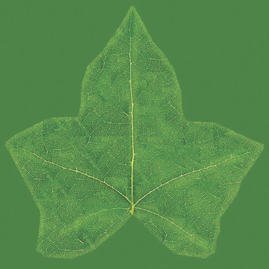
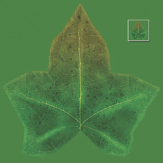
The Unsharp mask filter was able to sharpen the details on a per-pixel basis, bringing all those details you spent so much time on back into focus, even at such a small resolution. In Figure 2.15 and Figure 2.16, you can see the final diffuse texture and how it applied in Maya onto the leaf meshes.
Now, after you create a simple diffuse texture for the vine, it'll essentially be completed. The vine is a very thin piece that's not meant to draw too much attention. It merely needs to keep the leaves together in a logical way. The leaves are the main focus and the main thing needed for believability, but if the vine weren't there, you'd instantly notice the floating leaves and wonder where it was. I've prepared a final scene as an example on the DVD called Ivy04_Vine.ma. You'll now move on to the chapter's next project and expand on the practice of using opacity maps by creating a tree.
Trees can be such a hassle in games—so much so that there are several tools and software plug-ins that are used for the express purpose of creating trees and plants to take a lot of the burdens off the artists. But whether they are generated procedurally or individually by hand, trees are a necessary object in most games, and in many cases, games need lots of them. Being on tree duty can be pretty boring and repetitive. (Don't get me started on being on rock duty!) For this project, you'll learn how to create one that isn't your typical oak or pine tree but instead a more interesting and stylized version of an African acacia tree, such as the ones found in these reference images (Figure 2.17).

Before you begin, it's important to know ahead of time how a tree will be used. For example, will the player be able to stand next to it? Or will it only be seen from a distance? Will the player's experience only be on the ground and therefore, will the player only look up at the tree? Or will they be able to fly and look down on it? How will it be placed in the scene? Standing upright like a normal tree? Or will it be on its side, as if it had been cut down? There can be many factors involved. For your tree, assume that the game doesn't allow flight and that the players will be able to see the tree only from the ground, looking up at it.

The reason knowing this is important at the outset is because it dictates how you will construct the tree. You can focus all of your time ensuring that the tree will look good from the player's only vantage point and not be too concerned if it looks odd from above.
A good example of this is the extremely popular game World of Warcraft. As this game was first released, when players started out they were only able to walk, run, swim, and ride a horse (or some other animal). Occasionally, a player could hop a ride on a zeppelin or take a ride on a winged animal to get from point A to point B, but these flight paths were fixed, and the player couldn't control the flight's direction or elevation. After a year or two, the game released an update that allowed players to enter another world where they could obtain flying mounts, which allowed them to fly anywhere they wanted! This was very fun for players in this new world; however, the game designers decided that these new, winged mounts could not be used in the original game world. They were only allowed in the new area that had been expressly designed for this kind of gameplay.
The reason for limiting this new mode of travel was because the original game world was not designed with player-controlled flight in mind. There were entire cities that would completely look ridiculous if the player could see them from the air!
Note
Before starting, make sure you set your project to your project directory by going to File → Project → Set.
With this in mind, don't be surprised if your tree in this project looks rather ridiculous from above. Luckily, the players in your fictional game won't ever see that. All they will see are great-looking trees from the vantage point they were designed to be seen from.
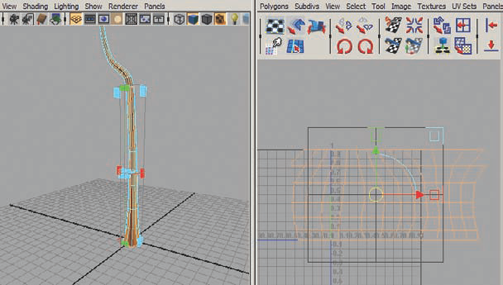
Begin with a new Maya scene and create a polygon cylinder. Position it as if it were set on the grid, and under the polyCylinder1 Inputs in the Channel Box, set the Subdivisions Axis to 12, Subdivisions Height to 6, and the Subdivisions Caps to 0. Scale the cylinder up to be a tall trunk for your tree. This will be the starting point.
Press the F2 shortcut key to switch the current menu set to the Animation menu set, if it isn't already. With your object selected, select Create Deformers → Lattice. Adjust the lattice points to shape the trunk so that it tapers from the base to the tip of the trunk (Figure 2.18).
Continue to adjust the lattice points to insert some bend into the trunk and some flaring in the trunk's base. The idea is to get rid of the straightness and add in some natural-looking curves. Once you have the trunk to your liking, you can delete the mesh's history to bake in the lattice's changes and remove the lattice.
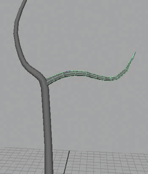
In the Front or Side view, use the CV Curve tool (found under the Create menu) to create a curve from the top of the trunk to the tip of your tree's main branch like in Figure 2.19.
Position the curve so that its end is centered on the end-face of your trunk and rotate it so that it isn't straight up and down but flowing in the same direction the trunk is, so that when you attach them in the next steps, they'll merge together smoothly.
Return to the Polygons menu set, if you haven't already, by pressing the F3 shortcut key. Enter Component Select mode and select the face on the end of your trunk. Hold Shift and select the curve. You should now have the face and the curve selected at the same time. With the selection still active, select Edit Mesh → Extrude. You'll notice right away that a new section of trunk has extended off the face and stretched across to the end of the curve. But that's not exactly what you want.
Under the polyExtrudeFace1 Input in the Channel Box, scroll down toward the bottom of the available settings and increase the Divisions setting to 14 and the Taper setting to 0.2. If you like, you can also add some slight Twist to the branch as well. After applying settings you like, you should have something like Figure 2.20.
The tip of the branch is a bit too straight in my example. To add a few divisions, I'll use Edit Mesh → Insert Edge Loop Tool. With this tool, you can click an edge and have a new loop of edges be inserted into the mesh. Do this a couple of times to add a few edge loops anywhere the branch or trunk look too straight. You can then move these new points to add more curvature.
Select the face on the end of the branch and select Edit Mesh → Merge To Center. This will collapse the face down into one point. Select the rings of vertices leading up to the point and scale them to make the branch taper gradually to the end.
Let's create another branch. Use the CV Curve tool in the Side or Front view to create the path of another branch off the trunk, as in Figure 2.21.
Create a NURBS circle and scale it down to about the diameter of the branch you want. Select it and then hold Shift and select the branch's path curve to add it to your selection.
Open the Surfaces menu set. Select Surfaces → Extrude → Options. Use the same settings you used before for the ivy vine, except this time, you'll increase the Number V value to 2. Keep the Number U value at 1 as before. Click Extrude to apply the command.
With history still active, you can select the branch's path curve (not the mesh) and reposition it on your trunk to perfect its location if needed. You can also scale the circle if your diameter is a little off from what you wanted. When you have your position and diameter as you like, you can delete the mesh's history.
Select the vertices at the tip of the new branch and use the Merge To Center command again to sharpen the tip to a single point.
Select the adjacent rings of vertices and scale them to create a tapering look to the branch. You can scale the base of the branch out some if you want to flare it, but don't have it extend beyond the shape of the trunk.
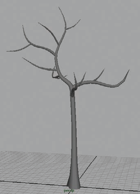
If any additional edge loops are needed to improve the branch's curvature, you can add them now as well. Eventually, you should get something like Figure 2.22.
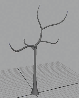
You can duplicate, reposition, and scale the existing branch to make new ones, or you can repeat the previous steps to make new branches from scratch. Whichever method you choose, make about three or four more large branches and position them on the tree to make an interesting shape. Mine turned out like Figure 2.23.


Adding smaller, secondary branches growing from the main branch system is pretty much the same process. The only real difference is that the branches are smaller. These branches will help fill out the rest of the tree's structure as well as provide a base that your future leaves can be attached to.
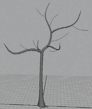
As before, in the Front or Side view, draw out a curve using the CV Curve tool coming off of one of your main branches. Once you get a nice curved shape using around 4 to 5 points, position it in the Perspective view so that it's accurately positioned on the tree branch.
Duplicate this curve and position it around the tree. Scale them up and down slightly to ensure they aren't all identical. I placed about seven branches (Figure 2.24).
Just as before, create a small Nurbs circle to use as an extrusion profile. Perform extrude commands for each branch curve and adjust their shapes to create a tapered affect from their base to their tip. When complete, you should have something like Figure 2.25.
With the ivy, each plane you created was an individual leaf. For a vine of ivy with a few dozen leaves on it, it's not too big of a hit to a game engine or to your time to place them each by hand. A tree, on the other hand, is a different story. You really can't place each individual leaf in the same way. Not only would it be extremely time-consuming, but it would result in a polycount far exceeding what most games would probably be able to budget to a simple tree.
With that in mind, you'll now create a couple of textures that contain a large number of leaves that you'll use to populate your tree. Rather than the relatively realistic style you've used so far in the brick wall and ivy vine, you'll try a more cartoony style, similar to what was used in Nintendo's The Legend of Zelda: The Wind Waker. Such a texture style doesn't require as many different maps as the realistic styles do, but you'll still need a diffuse map and, of course, your trusty opacity maps. You'll start with a texture base, as usual. This time, you'll render your leaf texture sources directly from Maya's native renderer.
First, hide your tree geometry while you work on your leaves. Select your entire tree. In the Layer Bar (found under the Channel Box) create a new layer and name it
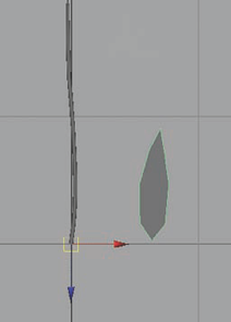
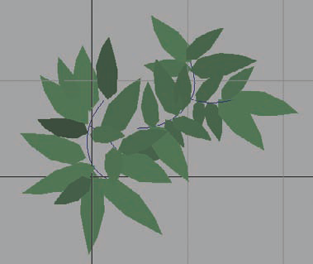
Tree. With the tree still selected, right-click the layer and choose the Add Selected Objects option. Click the V icon next to the layer to toggle its visibility off, thereby hiding the tree from view.In the Top view, create a small branch with leaves growing off it. First, draw out a curve that is mostly straight with some slight curvature to give it a natural look. Extrude a Nurbs circle along it and taper the ends just as you have done for the other branches you've made.
Select Mesh → Create Polygon Tool. Using your left mouse button, drop points into the shape of a leaf, similar to Figure 2.26. Press Enter when you're done to finalize the action and create the polygonal object.
Press the Insert key to toggle Edit Pivot mode and move the leaf's pivot to the base of the leaf, where it will most likely meet the branch.
Move, scale, and rotate the leaf to place it on the branch. Duplicate and repeat this process until the branch is covered in leaves to your liking. Scale them in such a way that, as the leaves approach the tip of the branch, they get smaller and thinner. Toward the base of the branch, the leaves are thicker and larger. Mine ended up like Figure 2.27.
Think of these as your tertiary branches. Rather than spending precious geometry on them, you'll give them a 2-polygon plane to give the illusion of more detail.
Apply a new Lambert material to the leaves and give it a forest green color. Apply another Lambert to the branch and give it a brown color.
Now you'll render an image of the branch to use as a texture for your tree. Select Window → Rendering Editors → Render Settings. These settings control how Maya renders an animation or a still image. Under the Common tab near the top, scroll down to the Image Size section and change the width and height to 256×512.
Under the Maya Software tab, near the top, change the Anti-aliasing Quality setting to Contrast Sensitive Production. Under the Multi-pixel Filtering section, make sure to deselect the Use Multi-pixel Filter check box.
The multi-pixel filter tends to blur your textures, especially if your textures are dealing with any kind of text or small details. I generally just turn multi-pixel filtering off as a rule.
Back in the top view, in the panel view menus select View → Camera Settings → Resolution Gate. Also check the Vertical option rather than the default Horizontal, if it's not already. You should see a box appear. Position your camera as best you can so that the branch is within the box. When you have it positioned, you can render it by clicking the Render Current Frame button at the far right of the Status Line (Figure 2.28).
Save the render as
branch.tga.Create a new layer and call it
branch_sourceand put the branch geometry into it and hide its visibility. Unhide the Tree layer.Create a polygon plane with a width of 25.6 and a height of 51.2. Make sure the Normalization option is off. By creating the plane with these dimensions, you've maintained the size ratio of your 256 × 512 texture, so once it's applied, it won't be distorted.
After applying your branch texture to the plane, press the Insert key on the keyboard to edit the plane's pivot point. Move the pivot to the base of the branch where it would attach to the tree.
Select Edit Mesh → Insert Edge Loop Tool and drag a new edge down the middle of the plane. Select the two long edges of the plane and move them either back or forth a bit. This will give the branch a bit of depth rather than it just being a simple plane. This wedge shape can more easily be seen from multiple directions and is more pleasing to the eye as an organic shape.
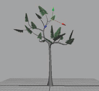
Position the tertiary branch onto the ends of one of your preexisting branches. Duplicate and position more branches around your tree. Focus on placing one at the tip of each main branch and have a couple more branches spaced around to fill the tree out (Figure 2.29). Don't forget, these are simply your third round of branches. You will make some new leaves to act as "filler" in the next steps.
The next texture will be the filler leaves for the tree. These will be the leaves that make up the majority of what is seen in the tree's canopy. Unlike the branch texture, this texture won't have any sort of "attach point" that obviously gives a position where it should meet the tree. These sorts of filler details are designed to literally fit pretty much anywhere and be scaled, rotated, and even intersected to give the illusion of depth and abundance of detail where there isn't any.
Hide your tree (be sure to add your new branch planes to the tree's layer) and unhide your branch_source layer. Move your branch geometry to the side.
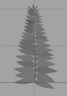
Grab one branch of leaves, duplicate it, and move it over to a clear spot to work with. Use your CV Curve tool to draw out short lines that would represent small branches and position them in a clumping pattern. You'll probably need to adjust them later, but it's good to get a starting foundation.
Start duplicating and positioning your leaves around the clump of curves (representing branches), scaling and rotating them (to diminish their uniformity), with the intention of creating a scattered leaf/branch combination of details, similar to Figure 2.30.
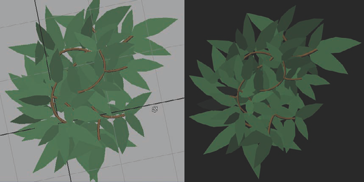
Extrude a Nurbs circle along the branch curves as you have done before. Don't worry about tapering the ends or anything. Select the entire leaf cluster and delete all of its history. You can then group the leaves all together with Ctrl+G. Duplicate the group to make a new clump of leaves and position them below the first group and rotate and scale it so that it's not positioned exactly the same as the first group.
Depending on how dense your leaf cluster is, you may want to duplicate a third copy. Assign your green leaf and brown branch materials accordingly. With these duplicates, I have this result from the Top View camera (Figure 2.31).
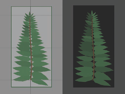
Now, you'll render an image to use as a texture just as you did with the branch. Use the same settings as before, except this time, make the width and height values equal 512, resulting in a 512×512 texture. Save it as
treeleaf.tga.Assign the cluster geometry to the branch_source layer and hide it. Unhide your tree layer.
Create a square polygon plane and apply your leaf texture to it. Because it is just a flat plane, it doesn't really help us fill the tree with natural-looking leaves. Let's add another dimension to it.
Select the leaf plane and select Edit Mesh → Poke Face. This will insert a vertex in the center of the plane. Raise the vertex up so that the plane becomes a pyramid shape.
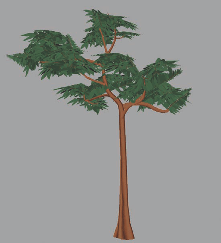
Begin placing, duplicating, scaling, and rotating the leaf planes around your tree, creating an interesting-looking canopy. Don't be afraid to intersect them and extend beyond the strict boundaries of the 3D branches. My result looks like Figure 2.32.
The bark of your tree should match the cartoony look that you've created with the leaves and branches. There aren't really any photo sources you can find to get those kinds of results. It'll have to be done with actual painting by hand. As with any kind of art, painting takes practice. I know as a professional 3D artist, I tend to neglect the 2D aspects of my talent and don't draw or paint nearly enough. It's a pretty common thing in this industry. Try to always reserve time for you to practice drawing and painting. Only through practice will you be able to maximize your potential and your talent.
But even if you feel you aren't a good texture painter, you'll probably be able to do this cartoony bark texture justice. If your first texture doesn't come out quite like you want, don't be afraid to try again. Learning from your prior mistakes is one of the best ways to improve your skills.
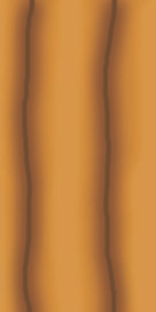
In Photoshop, create a new file that is 512×1024, making a tall, vertical image file.
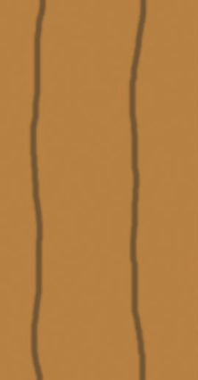
Fill the background with a similar brown color as you did with your branches previously.
Make a new layer. Name it Grooves. Take a soft brush and choose a darker hue of your brown color. Draw two relatively (but not completely) straight lines from the bottom of the image to the top using a small diameter brush, dividing your image into thirds. My brush is about 20 pixels wide (Figure 2.33).
Right-click the Grooves layer and open the Blending Options. Check the Outer Glow style check box. Change the color from the default pale yellow to a darker brown hue. Continue by making the following changes:
Blend Mode:
Multiply
Opacity:
35%
Noise:
8%
Spread:
9%
Size:
68 px
You should get a "shadowing" effect around your two groove lines, making the grooves look as if they are intruding into the surface.
Create a Brightness/Contrast adjustment layer over the Grooves layer and change the Brightness to +21 and the Contrast to +15. Select the mask (the white box on the layer) to make it active and fill it with black, thereby hiding the adjustment layer's effects. Take a black brush and paint over the areas between the groove lines, making that space lighter and giving the illusion of height.
Drag the adjustment layer to the New Layer button to make a copy of it. Select the copy's mask and press Ctrl+I to invert the mask.
Double-click the new adjustment layer to access its settings and change the Brightness to +3 and the Contrast to +25. You should have something like Figure 2.34.
Feel free to continue to adjust the bark's colors and settings until you get something you are happy with.
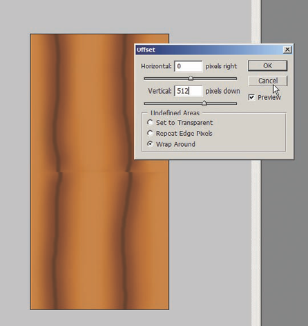
Now that you have some basic shapes, you'll want to make sure that it properly tiles, because you'll want this texture to wrap around the tree's trunk and repeat as it extends up the trunk's length. Press Ctrl+A to select the entire canvas and press Ctrl+Shift+C to Copy Merged. Finally, press Ctrl+V to paste the copied image of the bark into its own layer. Name this layer
BaseBark.With this layer selected, select Filter → Other → Offset. The Offset dialog box will open with two main sliders to adjust. Type 256 into the Horizontal slider. This offsets the texture 256 pixels horizontally (or half of your image's total width of 512 pixels).
In my case, it turned out that my texture looked good already tiling in that direction, but if you see any harsh lines running down the center of your image, get rid of them and apply the Offset filter again to put the image back to its original position.
Once again apply the Offset filter and remove the 256 from the horizontal slider (making it 0) and type 512 into the Vertical slider, inputting half of the height of your image. This offset result gave me an obvious seam that I'll need to fix in the next steps (Figure 2.35).
Apply the Offset filter once again to return to the image's original position. Select the Rectangular Marquee tool (or press M) and at the top of the screen, change the Feather option to 5 pixels.
Select a box around the middle of your image. You'll notice that the corners of your selection box are rounded, indicating that the selection is feathered. This is what you want, but you want the feathering to apply only to the top and bottom of the box, not the left and right edges.
With the selection still active, choose Select → Transform Selection. The Transform Selection tool allows you to interactively manipulate the selection boundary you have already drawn without manipulating the image within it. Hold down the Alt key and click and drag on the left or right handle of the Transform tool to widen the selection box to extend beyond the boundary of the image. Now the feathered edge will not feather the tiling border of your selection.
Press Ctrl+J to copy the selected area into its own layer. Name this layer
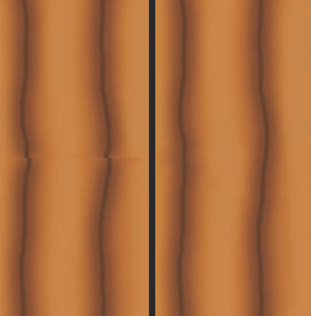
Patch.Select the BaseBark layer again and apply the offset filter, offsetting it 512 pixels vertically. You'll notice the Patch layer is overlaid on top of the seam you had before, although in my case, it hasn't perfectly fixed it right off the bat. I still need to make some adjustments.
In my particular image's case, I need to move the Patch layer around a little bit to best fit along the grooves I had drawn earlier. Then, I make a few strokes of the eraser to remove some trouble spots, and I am good to go. Here are my before and after results in Figure 2.36.
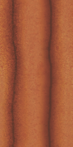
To add a little texture to your colors, you'll use an overlay image. From your texture library or from this book's DVD, pick out an image that provides some splotchy details. I chose a metal texture source. Add it to your Photoshop file as a separate layer and name it
Details. Change its Blending Mode to Overlay.Using the Free Transform tool (Ctrl+T), move and scale the image to lay on top of your bark texture in an interesting way. You may need to lower the Opacity of the layer, depending on how much contrast it has. I lowered my Details layer's opacity to about 36 percent.
Feel free to adjust the colors and remove any seams that the new Details layer may have added and save your finished bark texture as
bark.tga(Figure 2.37).
Back in Maya, if you apply your new bark texture to the tree's trunk, you'll probably notice that it doesn't quite look like you expected it would. Maybe it's all stretched out or has really ugly seams crisscrossing throughout the mesh. This is because the mesh needs to be UV mapped. UV mapping is the process of laying out your geometry's UVs to fit the textures you make for them. To get started, you'll open the UV Texture Editor from the Window menu.
You'll first get the hard part out of the way and begin with the tree's trunk. Select the faces that make up the straighter part of the trunk, starting from the base and ending right before the trunk begins to bend.
Under the Polygons menu set, select Create UVs → Cylindrical Mapping. A cylinder-shaped manipulator will appear around the tree trunk and the selected faces will appear in the UV Texture Editor window. You should see something like Figure 2.38.
If your results are like mine, you may notice that in the upper left and right of the UV shell that is currently active there is a face hanging by itself along with a gap where it should be on the opposite side. To fix this, you'll need to do some manual UV adjustment.
Right-click in the UV Texture Editor window and choose UVs from the marking menu that appears. This will allow you to manipulate the UVs in the editor. Select the UVs of the trunk that you just mapped and move them to the side so that the rest of the UVs won't interfere with your work.
Right-click in the UV Editor and this time choose Edge component mode. Select the edge that connects the hanging face to the rest of the UV shell and in the editor's menus select Polygons → Cut UV Edges (or click the "cutting scissors" button on the toolbar). This will separate the face from the rest of the UV shell.
Now, select the two edges on the other side of the UV shell that border the gap that you want the hanging face to attach to. You'll notice that this also selects the corresponding edges on the hanging face. That's because the two edges you've selected are the same edges on the geometry. With these two edges selected, select Polygons → Move And Sew UV Edges. The hanging face should move to the other side and merge into the shell where the gap previously was.
Now that you've cleaned up any hanging faces, you'll want to position these UVs in a clean grid. The easiest way to do that is to select each individual column of UVs and use the Align command.
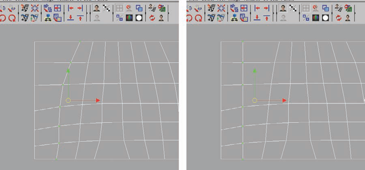
On the UV Editor toolbar, you should see four buttons with arrows pointing in all four directions. These are the align buttons. Depending on which directional button you click, the current UV that you have selected that is the furthest in the selected direction will be the UV that the rest of your selection aligns to.
Look at Figure 2.39 to see what I mean. In the first image, I have a column of UVs selected that are not aligned. The UV at the bottom of the column is the farthest UV to the left out of those I have selected. So when I click the button with the left-pointing arrow, all of the selected UVs line up as in the second image. Do this with each column of UVs to straighten them all out.
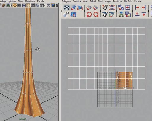
When your UV shell is straightened out, you can start positioning it within the Editor to get the results you want on the tree. Scale, position, and if applicable rotate your UVs as you watch the result on your tree geometry. When you have a layout that you like, you can move on to UV mapping the rest of the trunk in the same way. Mine turned out like Figure 2.40.
For the rest of the trunk, continue to select sections of faces and UV map them. Then go in manually to tweak and clean up the results.
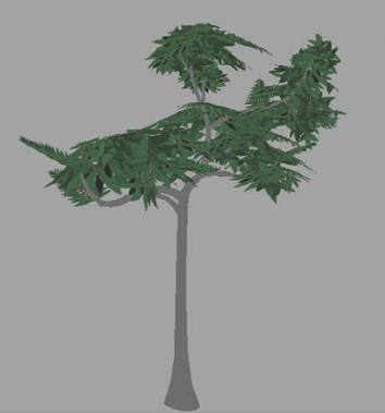
Do the same for each of the branches until finally your entire tree—trunk, branches, and leaves—is UV mapped. Position each shell of UVs in the editor to get the kind of look you want. Mine ended up like Figure 2.41.
The final tree came out to about 1,800 polygons, which is a very conservative number in this current generation of game consoles. You could have several varieties of trees of this polycount range without too much of a problem.
As you can see from both the ivy and the tree, when it comes to vegetation, smart usage of opacity maps can make all the difference in creating the illusion of the details you strive for. And it works well for both realistic and stylized genres. Plants, flowers, grass, and more can all be made using the methods described in this chapter. In the next chapter, you'll tackle something man-made.