
As an environment artist, you can bet that buildings will be a big part of what you do on the job. In fact, most environment artists get their start doing miscellaneous background structures. As you get more experienced and more responsibility, more of the foreground elements will be assigned to you. But even the most experienced environment artists get called upon to do buildings and structures from time to time. The trick is to enjoy it, no matter what level of experience you have!
Just saying the word building can bring up hundreds and thousands of different images in your mind. Or in a Google image search! There are limitless combinations of shapes, styles, and uses for any structure. To create that same sense of limitlessness in a video game is impractical, not to mention entirely impossible. If you look at the buildings in any of the popular games that are set in a large city, such as inFamous or Grand Theft Auto IV, you'll inevitably run across the same building being used in multiple locations.
The main reason for this is simply resources. Sure, it is possible to create hundreds or thousands of completely unique buildings to populate a city, but what about the memory requirements of such a task? Even considering the dense amount of information that modern consoles and computers can handle, there's just not enough space on the disk for that much information. But let's say that space on the disk is no issue. How long do you think it would take to make that many structures with the average development team? Years? And at what cost?
No, it's much more practical to reuse buildings in different parts of the city as much as possible, but in ways that aren't obvious and that don't take away from the player's experience of the game or the setting. One method that is used to help speed up the process of city building is building modularly.
The process of building modularly is creating a series of parts (or modules) that can be put together in different ways to create several variations. For instance, if you create a block of windows, a door, and a roof, you can pretty much arrange them in any number of ways to create differently shaped, generic buildings. Do this on a large scale, and your city can become unique looking.
For this lesson, you'll create a skyscraper using the process of modular building. You'll create 10 modules and use them to put together the structure. At the end, I'll demonstrate a few different examples of this.
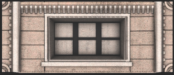
Even if you're building modularly, having a reference to use as a guide is always useful. I chose to use the Smith Tower in Seattle, Washington, as the model for this project. I took the liberty of snapping a few photos to use here as reference in Figure 5.1. You can also use the Internet as a valuable reference resource.

You aren't necessarily going to copy the images precisely. The idea is to use the image as an idea resource. Some details you can expand on yourself; others you can gloss over completely because they are unnecessary. Take a look at Figure 5.2. In this image, I've highlighted the key parts (or modules) that your modularly built skyscraper could be composed of, using this reference image.
If you look at what is highlighted in the figure, you may be able to tell that you wouldn't be able to duplicate the building 100 percent perfectly using just those individual pieces, but you would be able to create a pretty good representation of it in a game. That is the ultimate goal. Not only that, you could create several more variations of the building using the same pieces. So, with the work you do for this one building, you'll end up with the pieces to create a dozen more structures if you want.
Note
Before starting, make sure you set your project to your project directory by going to File → Project → Set.

To get started, you will create a generic block of windows that can be used to make up the majority of the building's surface detail.
Start a new scene and set your project to a new project directory.
In the Front view, create a plane that is 35 units wide and 15 units high. Position it so that the left side is even with the origin and the rest of the plane extends to the right.
In the Perspective view, choose Create → Polygon Primitives → Pipe. Draw out a quick pipe and then change the settings under the Inputs in the Channel Box to be as follows:
Radius:
1.75
Height:
1.15
Thickness:
0.5
Subdivisions Axis:
40
Center the pivot and point-snap it to the upper-left (or upper-right, depending on the orientation of your scene—my example is to the left) corner of the plane.
Select the forward-facing edge loops of the pipe and apply a Bevel command to round them.
Duplicate the pipe and point-snap the duplicate to the lower-left corner of the plane.
Back in the Front view, create a tall, thin cube next to the two pipes that extends beyond the top and bottom of the plane. Just as with the pipe meshes, bevel the two forward-facing edges.
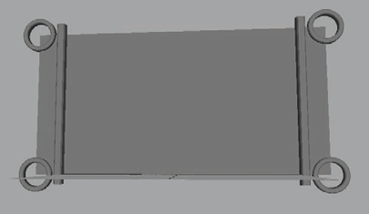
Duplicate both pipes and the cube and mirror them to the other side of the plane. You should have something like you see in Figure 5.3.
Select the plane and apply an Extrude command. Without pulling the extrusion out any, scale it inward. Then apply a second extrude and push it inward, creating the frame that will house the windows. You'll have to delete the extra face that is left behind when extruding from a plane. Also, don't worry too much about the exact shape of the window cavity. You'll get back to that in a later step.
Next, create a cube that is about 6 units long, 3 units tall, and 3 units thick. This will be a brick that will cover the majority of the surface between all the windows and columns on the skyscraper.
Bevel the front face of the brick. Then bevel the four corner edges to round them out as well.
Place the brick on the lower-left corner of the plane, so that its right side is flush with the tall cube. Also, make certain the bottom face is even with the grid. Duplicate the brick and move the duplicate up until it sets on top of the first brick. Do so again until you have 5 bricks set on top of one another on the left side of the plane. If you need to adjust the bricks to fit within the 15-unit-tall area that the plane marks out, you can.
Duplicate the column of bricks and mirror it to the other side. Duplicate them again and move them on the other side of the cube divider, so that their left side is flush with the side of the tall cube. Duplicate and mirror this brick stack to the other side as well.
You'll more than likely need to adjust the size of your window cavity to fit within this brick border on either side. You may also need to bring the four circular pipe shapes and the two tall cubes outward some to stick out from the bricks. At this point, you should have something like Figure 5.4.
Next, in the Front view once again, create a long horizontal cube that stretches across the top of the wall from the left cube divider to the right. Pull it out to extend beyond the bricks and is even with the two bordering cubes.
Select the bottom edge of the front-facing side of this new cube and pull it up, creating a wedge shape. Bevel the two front-facing edges. This cube will serve as a frieze, which is a structural band that runs along the tops of doors or windows. You should have something like Figure 5.5.
Duplicate one of the top bricks and place it above the windows, flush with either the left or right brick columns. Grab the vertices on the opposite side of the brick and pull them to the other side of the window, creating one long brick above the window opening.
Duplicate it and place it below the window as well, filling in the rest of the blank space.
In the Side view, use the Create Polygon tool (under the Mesh menu) to create an upside-down, L-shaped polygon similar to Figure 5.6. This will become one of many in a series of dentil molding that forms a decorative band along the top of the window blocks below the frieze.
Return to the Perspective view. Extrude the polygon out about 1 unit to give it some thickness. Bevel the sharp corners to round them a bit. Place the polygon below the frieze and above the window, leaving a little space between it and the left-side dividing cube. If you need to adjust the shape to make it fit, do so now.
Duplicate the dentil block and move it to the right, leaving a space between the two that is about the same width as the dentil block. Press Shift+D several times to use the Duplicate With Transform command, until you have the entire row filled with the molding blocks like in Figure 5.7.
Duplicate the frieze and position it below the window. Shorten it so that it extends just a small amount beyond the left and right sides of the window and raise up the bottom edge, removing the wedge shape. Push it inward slightly so that it isn't extending beyond the bricks quite so much. This will simply be a window sill.
Next, you'll add the windows. In the Front view, choose Create → Polygon Primitives → Cube. Draw out a cube that fills in the hole that you made for the windows.
In the Inputs section of the Channel Box, increase the Subdivisions Width setting to 3, thereby dividing the cube into three sections.
Select the two dividing edge loops and bevel them, adjusting the offset to be about 0.2. This gives you two thin strips of geometry placed equidistantly apart.
Select all the faces except the two strips and extrude them, pushing them inward to cause the two strips of geometry to protrude outward from the cube. Position the cube into the window cavity.
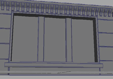
Bevel the forward-facing edges of the two strips of geometry. This will give you the shape of three windows divided by a frame (Figure 5.8).
Create another pipe. Change its Thickness to 0.4 and its Subdivisions Axis to 4 to create a square shape. This will be the main frame of the window.
Rotate the frame 45 degrees to straighten it and select Modify → Freeze Transformations. This command will bake the object into place, removing all transform changes and keeping it at its current position and shape. Rotate the frame 90 degrees forward to stand it up.
Go into the Front view and reshape the frame to fit the window cavity. The easiest way is to grab the top vertices, and move them into position, then grab the left side's vertices and move them, and so on. Work your way around the shape in this manner until it's completely in position.
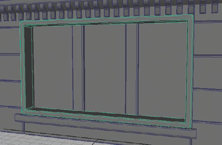
Bevel the forward-facing edges as well as the four corner edge loops (Figure 5.9)
Create a long cube and place it in the middle of the windows horizontally, forming a horizontal bar for the frame to separate the panes of glass. Bevel the forward-facing edges.
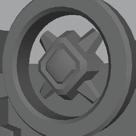
Add a decorative shape (or combination of shapes) in the center of the four corner circles. This can be whatever you want. I created a few beveled cubes and arranged them in a flowery pattern as in Figure 5.10. Duplicate this pattern to all four corner circles.
This block of windows will form the majority of the building. It will be duplicated and snapped end to end and top to bottom to form a large wall of windows. Next, you'll create a corner column to go on the corners of the building.


At the edge of a building's walls, where two walls at 90 degrees form a corner, there is usually a column. The corner column forms a supporting as well as a framing structure. This structure will add a framing shape at the corners, which will help relieve a building's sharp edges and make it look much more structurally believable.
Create a cube that is 5 units wide, 5 units deep, and 15 units high. This will act as the base of your column. For the purposes of this lesson, the front-right edge will be the corner that will face the exterior of the building.
Select that front-right edge and bevel it, making the Bevel Offset about 0.25 if you are following along with my measurements.
Increase the bevel's Segments value to 2, creating a new edge through the middle of the beveled surface.
Select the connector edge that forms on the top and bottom caps of the column and delete them.
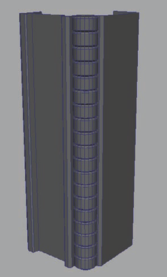
Select the center edge and move it inward, forming a square-shaped cavity that runs along the entire column like in Figure 5.11.
Select all the vertical edges of the column (none of the ones bordering the top and bottom) and bevel them slightly, rounding the hard-edged corners.
Delete the top and bottom faces of the column for now. You won't need them in later steps.
Go to the Front view. Select the front face and with the Cut Faces tool (under the Edit Mesh menu) hold Shift and cut a straight, vertical edge through the center of the selected face.
If you didn't quite cut it in the center and need to adjust the cut's position, you can by clicking the polyCut1 Input item in the Channel Box on the right side of the screen and change the Cut Plane Center X value to 0. This will move the cut to the center of the face.
Select the newly cut edge and bevel it, giving it an Offset value of about 0.7 to create two thin, vertical faces running along the sides of the forward-facing side.
Select the center face and extrude it inward, creating a cut path through the center of the column's forward face (Figure 5.12).
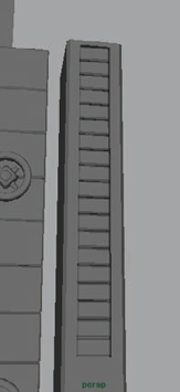
Go to the Top view. Create a cylinder and using Maya's interactive creation, draw it out to fit within the corner alcove of the column, as in Figure 5.13.
Back in the Perspective view, adjust the cylinder's Subdivisions Caps to 0. Select the top vertices and lower them down to make the cylinder about 1 unit tall.
Select the top and bottom faces of the cylinder and bevel them slightly to round the hard edge.
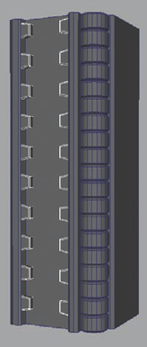
Duplicate the cylinder and place the duplicate directly above the original. Continue duplicating the cylinders (you can use the Duplicate With Transform command with the Shift+D shortcut keys to make this easier) and placing them above the previous one until the cylinders form a small column all the way up the height of the main column shape.
If you find that the topmost cylinder extends beyond the top of the column's base shape, you can select all the small cylinders, group them together, and scale the group down until they fit perfectly. Then make certain you Ungroup (Edit → Ungroup) them afterward (Figure 5.14).
At this point, you can start adding whatever details you want. If you want to skip to the next module now, you can. If you'd like to follow along with me, create a small cube.
Bevel the cube and make one end shorter than the other. Place it within the forward-facing ridge. Duplicate it and place it every two units or so down the height of the column. Duplicate the cubes for the other side of the ridge, and you should get something like Figure 5.15.
You can place these teeth-like details along the left and right edges of the first module and the window block as well, if you want. You may come up with a detail later in the project that might look good on an earlier piece. Don't hesitate to go back and add it to improve the earlier work!
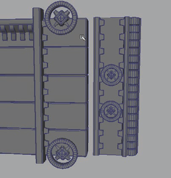
Select the circular corner details of the earlier module and duplicate them to use with the column module. Scale it down to fit and place two of them in the center of the large forward-facing side like in Figure 5.16.
Another detail you can trade between modules is the bricks. Duplicate a brick from the window block module and resize it and reposition it to fit with the column. Duplicate it and stack the bricks to fill the height of the column behind the teeth detail.
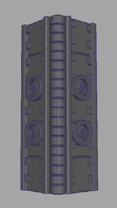
Once you've added all the details you want, you can duplicate and mirror one side of the column for the other and you'll have your completed column module (Figure 5.17).


It's good to have some variation. Allow yourself to have some details look different and, thus, more visually interesting. Of the 10 modules you'll be making for your building, two of them will involve windows. If you want, you could continue to make more variations on the window blocks. The more variation, the better—to a point. In a real project, you'll always want to make sure you are keeping within your rendering budget. The more variation you have, the more textures you'll be required to make, which will making the rendering of it all much more computationally expensive.
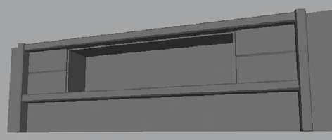
This second block of windows you'll be making in this section will share many of the elements of the first window block. This will keep their design consistent and allow them to be used together.
Create another plane. This one should be the same width as the first window block's plane (35 units wide to be exact), but this time, make it 10 units tall instead of 15. The windows in this module will be a bit shorter, so the plane will be shorter as well.
Place this plane directly above your first module. This will make it easier to duplicate consistent details between the two and keep them lined up correctly.
Grab the bricks from your first module, duplicate them, and move them upward to line up with the new module's plane. Do the same with the left and right dividing cubes. This will give you a result like you see in Figure 5.18.
Select the bottom brick on both sides and delete them. Grab one of the duplicated dividing cubes and rotate it 90 degrees to make it lie horizontally. Scale it so that it reaches across the module from the left dividing cube to the right and place it below the remaining bricks.
This will create an area for more decorative details that will act as a border.
Duplicate the horizontal cube you just placed and move the duplicate up to the top of the module to serve as a border.
Select the plane backing and apply an Extrude. Scale the extruded face to fit within the space that remains between the bricks. Extrude again and push back to create an opening for windows to be placed later. You'll probably need to delete the extra face that is usually left behind to reveal the window cavity (Figure 5.19).
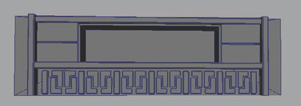
In the Front view, using the Create Polygon tool, use 6 points to draw out an L-shaped polygon. Extrude it outward to give it some thickness and bevel it, rounding the hard-edged corners.
Duplicate it, rotate it 180 degrees vertically and position the duplicate so that the two L shapes fit together like a puzzle, leaving a small gap between them (Figure 5.20). Scale them so that they fit within the gap below the window area.
Move the two pieces to the left side of the area beneath the windows. Duplicate them both and group the new duplicates together (Ctrl+G to group them). Scale the group −1 in the x-axis to flip them so that the shape faces the opposite direction.
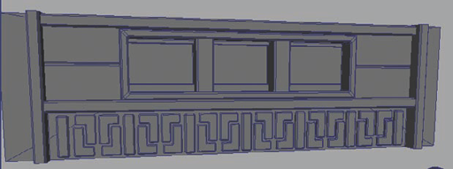
Ungroup the two shapes and select all four L-shaped objects. Group all four together and duplicate them a few times. Move each duplicate to the right so that the shapes fill up the space. If you have any space left over, you can create a few vertical, beveled blocks to go in between, like in Figure 5.21.
You can grab the window details from the first window block module to use in the second. Simply resize them to fit the window cavity and you're done (Figure 5.22)!


The roof ledge module will act as the top border of your structure. Rather than having the windows simply stop when they reach the top of the building, you can add this ledge to the top of the building to make it look more complete and rooted in reality.
Before beginning, think about how your game project handles the rooftops of buildings. In many games, the player will never be able to get to the roofs, so they don't necessarily need to be created. However, if your characters can jump over buildings in a single bound or pilot a helicopter and fly high above the cityscape, you may need to make sure that there actually is a roof. For this project, I'll be assuming that, like in a typical game, the player will not be able to see the tops of the buildings.
Create another plane to act as the base that you'll build from. Make it 35 units wide and 8 units high. You can place it above the other modules you've made to help you with placement and to make sure things line up.
In the Front view, create a tall cube that is 8 units high that will act as a section of dentil molding to form a band at the base of the ledge where it meets the windows below it.
Bevel the forward-facing edges of the cube to round its edges.
Place the cube at the far left of the plane. Duplicate it and move it to the right so that the duplicate cube is flush with the original. Use the Duplicate With Transform command (Shift+D) to continue to duplicate the cube across the surface, like in Figure 5.23.
Duplicate one of the molding cubes and rotate it 90 degrees so that it lies horizontally. Then flip it 180 degrees so that the beveled side is facing the structure. Grab one end of the cube's vertices and stretch it across the band of dentil molding, inserting it partially into the band.
Select all the original dentil molding cubes and combine them together (Edit Mesh → Combine). Delete the new combined object's history (Edit → Delete By Type → History).
Select the combined dentil molding mesh if it isn't selected already and Shift-select the horizontal cube that runs across them. Perform a Difference Boolean (Mesh → Booleans → Difference), cutting an indention across the surface of the dentil molding like that shown in Figure 5.24.
For the purposes of adding interest, you can select the top side of the indention and pull the vertices out, making the upper half of the dentil molding jut farther forward than the lower half.
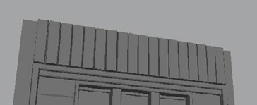
Create a rectangular cube above the dentil molding that is 35 units wide and about 4 units tall. Reshape the cube into a wedge shape that angles upward and extends out beyond the dentil molding that is below. Bevel the forward edges to round out their hard lines.
Select the topmost face of the wedge and extrude it upward about 4 units. Pull the forward-facing top edge outward, making it extend even farther forward.
Select the topmost face again and extrude it up about 2 or 3 units. You should have something similar to Figure 5.25, a ledge that demarks the boundaries of the roof.
Bevel the forward corners to round them off and soften their lines.
Duplicate the ledge. Select the vertices on the right side and move them over to the left until the duplicate ledge is only about 3 units wide.
Select all the thin duplicate ledge's vertices. Hold the W key and left-click and hold. This combination of key and mouse click is a shortcut to access the Move tool's options.
While still holding the left mouse button, drag the cursor to the left to hover over the word Axis. This will open a new marking menu. Move the cursor to hover over the word Normal and release. This changes your Move tool from its regular mode to Normal Axis movement.
Now that you are within Normal Axis movement, click and drag on the handle labeled N (demarking the surface normal direction) and pull all the vertices outward slightly.
Using the Normal Axis movement like this makes every vertex move outward relative from its own position rather than all of them moving in a singular direction as a group. It's very similar to the Push command in Autodesk's 3D Studio Max, if you are familiar with that application.
Return to World Axis movement by accessing the Move tool's options again (either the way you did above or by double-clicking the Move tool in the Toolbox and setting the Move Axis back to World). Move the small duplicate ledge (we'll call it a ledge block from now on) to the far left of the main ledge shape, making it flush with the left side.
Bevel the edges of the ledge block.
Duplicate the ledge block and move it to the right, positioning it flush with the original. Continue to Duplicate With Transform (Shift+D) across the ledge. If the ledge blocks extend too far off the right side, you can select them all, group them, and scale them as a group until they fit snugly (Figure 5.26).
Select one of the horizontal cubes from a previous module, such as one of the ones above and below the windows in the small window block (from Module 3). Duplicate it and move it up to the topmost forward-facing surface of the ledge. Scale it to stretch across the entire front face of the ledge and position it at the top of the ledge on the corner. Duplicate it and position it on the lower corner of the ledge's top face as well. It should look something like Figure 5.27.


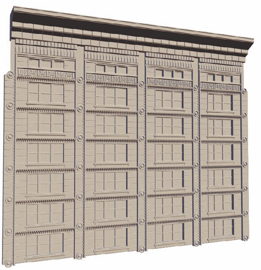
The ledge module is pretty much complete at this point. Feel free to continue to add all the details you want. At this point, with these four modules (large window block, small window block, corner column, and roof ledge) you can make a pretty convincing surface. By duplicating and stacking modules and placing them side by side, you could create a wall of detail similar to Figure 5.28. That's made just with four of our final 10 modules. Let's keep going!
Back in Figure 5.2, you can see that toward the top of the building, near the ledge, there's a different type of column being used on the corners. It is a bit larger and acts as a platform for the corner ledge. It also helps add more variety, which is always a good thing, especially when building modularly.
Create a cube that is 6 units wide, 6 units long, and 25 units high. Just as with the previous column (back in the Module 2 section), select the forward, right edge and bevel it, adding a second Segment and repositioning the center segment edge to carve an L-shaped wedge into the corner of the cube as in Figure 5.29. Don't forget to use Snap Align to help keep things square. Bevel all the vertical edges to round them a bit.
Note
Snap Align is simply the action of snapping in one dimension to align one (or more) points to another point in that same dimension. For example, to snap align two vertices in the y-axis, hold the V key (for Snap To Point) and left-click and drag the green y-axis handle from one point to another. The original point will snap to the second point's y-axis position, but remain unchanged in the other two dimensions.
Select the forward face and apply an Extrude from the Edit Mesh menu. Scale it inward. Select the bottom edge of the extruded face and lift it up, adding some space between the bottom of the column and the bottom of the extrusion.
Select the extruded face and apply a second Extrude. This time, move the extrusion in, pushing a cavity into the column's surface.
Create a small rectangular cube. Bevel all the cubes edges and place it within the column's cavity at the top. Duplicate the cube and move the duplicate down so that it is flush with the original. Continue to Duplicate With Transform (Shift+D) to create a column of small bricks stacked on top of one another within the cavity of the column, like in Figure 5.30.
Delete the other side of the column and mirror the details that you have so far to create an L-shaped column with both sides containing the brick column.
In the Top view, create another small cube and place it within the corner wedge of the column. Bevel its forward-facing edge to round the corner. Bevel the top and bottom faces of the cube as well to remove their hard edges.
Return to the Perspective view. Position this new cube about a quarter of the distance from the top of the column. Duplicate this new cube and move the copy down until it's a little above halfway down the side of the column. It should look something like Figure 5.31.
Select the column of cylinders from the small column (that you created in Module 2's step 14) and duplicate all of them. Place the duplicate cylinders in the larger column's corner wedge. Duplicate more cylinders to fill the space on the large column to run up the entire height.
To create a base and cap to the column, create another cube and add a wedged gap to its forward, right-side corner just as you did to create the column in step 1. Make this cube about 3 units tall and place it at the base of the column.
Duplicate the base and place it on top of the column as well. Modify the vertices of the cap to make it larger and extend farther out from the column so that it will effectively act as a support for whatever will be placed above it in a future step.
Create two wedge-shaped cubes to be placed beneath these flanges of the cap to act as further support.
You can continue to add details as you see fit, but in the end, you should end up with something like Figure 5.32.


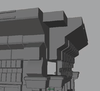
The next module on your list is to create a corner piece for the roof ledge. With the roof ledge piece you have now (Module 4) you can create straight and diagonal roof ledges, but when it comes to the corner, you'd need a new corner piece to fill in the gap that can been easily seen in Figure 5.33.
In the Side View, use the Create Polygon tool (from the Mesh menu) and draw out a profile shape for a decorative stone support. Mine is sort of seahorse shaped. You can, of course, make whatever kind of shape you'd like.
Extrude the drawn out profile polygon to give it thickness. Position it to sit on top of the larger column you made (Module 5 if you recall) so that it is centered on top of one of the platforms that make up the column's cap, like in Figure 5.34.
Select the ledge structure from Module 4 and duplicate it. Select the rightmost vertices and move them to the left to shorten the ledge piece to fit within the gap. It should be flush with the ledge that is to the left of the corner gap and extend to the edge of the large column, which in my case, is about 7 units wide.
Duplicate this small ledge piece and flip it 90 degrees to fit on the right side of the corner gap as well.
For this corner module, you'll create a stepped style corner. In a future module, you can create a more rounded corner module. First, create a cube and place it between the two ledge pieces to fill in the gap. You can make it the same height as the topmost section of the ledge, like in Figure 5.35.
For a moment, return to the decorative supports. You can continue to modify them to be as decorative as you'd like. I took my base shape and added a few details (Figure 5.36). They don't need to be too fancy as they will never be seen up close in the game. These little supports will be near the tops of the buildings most of the time.
Duplicate the support object and place it on the other side of the column so that it is centered on its cap ledge as well.
Now return to the corner ledge details. Select the two horizontal bars that run along the top of the original ledge you made, duplicate them, shorten them, and place them on the ledge corner section you have. Duplicate them and position them to follow the shape of the stepped corner.
You can also duplicate the other details of the ledge module onto this corner ledge module, such as the bricks and the dentil molding and whatever else you may have created that is different from my examples.
Remember the cube that sits within the gap from step 5? It's time to finish that bit. Select the bottom face of the cube and extrude it down to be even with the next section of the ledge. Scale this new extrusion inward to match the angle of the ledge. Once that is done, bevel the edges to round off the corners. You should have something like what you see in Figure 5.37.
Duplicate this corner cube and position it below the first so that it fills the gap below. Move the top of the cube's vertices upward to intersect into the cube above it.
Continue to modify this corner ledge module however you'd like. You can see my final results in Figure 5.38.


The roof module isn't so much a puzzle piece that can be plugged in like the rest, but more of a cap piece to any tall building you may make with this set of pieces. Not all buildings necessarily have to have a cap piece, but having it on top of a building instantly changes the building from a typical square building to a centerpiece structure with an intrinsic visual value that is different from the more typical buildings.
You can create a rooftop piece that looks however you like, but if you'd like to follow along with me, select Create → Polygon Primitives → Pyramid.
Using the interactive creation, drag out a tall pyramid that can be placed on top of a building, similar to the reference image in Figure 5.2. Rotate it 45 degrees to align its square base to be parallel with the rest of the modules.
Select the pyramid's apex vertex and select Edit Mesh → Chamfer Vertex. This will create a new square face on top of the pyramid, which will flatten its tip. Under the polyChamfer1 Inputs in the Channel Box, you can adjust the Width value down to something around 0.13 units to make the new face not quite so large.
Select the top face and bevel it to round the corners some. Select the edges running up the four sides of the pyramid and bevel them as well, increasing their Segments value to 2 and shrinking their Offset value down to something like 0.2 to give the edges a rounded profile.
Select one of the pyramid's four large faces. It doesn't matter which. Extrude it and scale the extrusion inward, giving the face a thick border. Scale this new Extrude again and push it inward, carving into the surface.
Select the large inner face of this new cavity and extrude it again, once again scaling it inward to create a border. And then once again extrude and push inward. This gives your border two distinct tiers.
Select the forward-facing edge loops that run around both tiers and bevel them to round the hard edges. You should have something similar to Figure 5.39.
In the Front view, use the Create Polygon tool to draw out the shape of an alcove. It can be whatever shape you want, but I followed the reference image from the start of the chapter and made it an arch shape.
Extrude this shape out to give it some thickness.
Duplicate it. Hold down the Control key and scale the forward directional handle on the scale gizmo (in my case, this was the Z direction).
Holding the Control key like this will lock the selected scale axis, causing the shape to scale only in the other two directions. This will make it keep the same depth as the original alcove, but expand it outward in the width and height.
Once you've expanded the duplicate arch, you can then let go of Control and scale the duplicate inward in the depth direction to make it not quite as deep as the original alcove. You should have a shape similar in style, as in Figure 5.40.
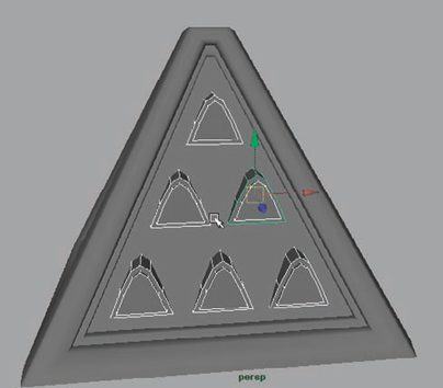
Place these alcove arches together at the top center of the large center face of the pyramid. Duplicate them and place two in the middle of the face and then place three more near the bottom of the face so that they are set almost like pool balls in a rack (Figure 5.41).
Now, using Difference Booleans (from the Mesh → Booleans menu), cut the alcove shapes out of the pyramid.
You can now detail the rest of the roof however you see fit. I took the rows of teeth-style cubes that were used on the window modules and ran them along the inner tier of the roof's border. I also beveled the edges of the alcoves to smooth them.
I would normally say you could now duplicate this side of the pyramid for the rest of the sides, but you don't actually need to do that (even though I did on the DVD video supplement material). Later on, you'll only be using one side of the pyramid to bake texture information, so for now, you need only make one side.
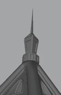
For the top of the pyramid, you can create a spire. Or make a steeple or a weather vane or a radio antenna—whatever you want. I created a simple steeple shape using a cylinder for a base and a cube that I extruded upward for the steeple itself. You can see it in Figure 5.42.


Note
Don't forget that if you expect your player to be able to get up to the roof and view it closeup, you should spend the time to detail it as much as you would any other part of the building. If it's going to be seen only from way down below, at street level, however, a little detail can go a long way toward the illusion.
As we get closer to the end of our 10 modules, you'll start to see that some of the modules you make are based on or even simply just parts of other modules. For example, the seahorse-shaped support structures from the corner roof ledge module (Module 6) will actually be duplicated and broken off to form their own support strut module. These support structures will run along the top of the ledges, to give the roof more structural support as well as to serve as a decorative way to break up all the straight lines that are up near the top of the building.
And, you don't necessarily need to be doing this right now because you will use the low-resolution version in the actual game. Since you will have the low-resolution version of the support structure completed for the corner roof ledge, you can simply use that support strut in the game as your eighth module. Creating it right now actually doesn't serve any purpose, but I'm going over it so you understand that when I said there would be 10 modules, I was telling the truth!
Module 9 is another module that takes parts from a previous module. The round roof ledge module is simply a variation on the corner roof ledge module. Instead of a cornered ledge shape to form a 90 degree angle, this one will be rounded, forming a smooth shape between each side.
Duplicate the corner roof ledge module and move it to the side. Delete the cube in the middle of the two ledge extensions.
Create a cylinder that is the same height as the top horizontal face of the ledge. Bevel the bottom.
Place it in the center of the corner. Scale it to fit, if it doesn't already.
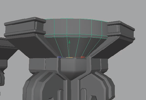
Select the bottom face and extrude it downward. Scale the extrusion inward to fit the angle of the ledge's downward slope like in Figure 5.43.
Use the Insert Edge Loop tool (from the Edit Mesh menu) to insert an edge loop around the top ring of faces to be level with the top border geometry of the ledge extensions on either side.
With the new edge loop selected, bevel it. Adjust the Offset value to make the width of the new ring of faces match the width of the top border geometry.
Select the ring of faces now, and use the Duplicate Faces command from the Edit Mesh menu to duplicate them as their own mesh.
Extrude this new ring of faces to give them thickness that matches the thickness of the border geometry to its left and right.
Bevel the forward-facing edge loops to match the beveling of the border geometry.
Duplicate the piece and move it down to match the elevation of the bottom border geometry. When they both match, you should have a flowing border such as the one seen in Figure 5.44.

The last module is a base wall support. This will be what goes around the base of the building so that it's not just windows at the bottom street level. Keep in mind that if the building is one that the player will actually enter, a door piece would also need to be made.
It can be difficult to find good reference of the base of buildings on the Internet. However, thanks to the magic of Google Maps' Street View technology, you can probably find what you are looking for with a quick address search. Luckily, I live near the Smith Tower, so I was able to take a photo to use here (Figure 5.45). You won't be duplicating this exactly, but it serves as a good reference.

Create a tall cube that is 6 units wide and deep, and 45 units tall. Center it on the origin. You can place Module 1 up above it as a size reference.
Bevel the four vertical edges to round the corners.
Duplicate the cube and select the top row of vertices. Move them down to shrink the duplicate so that it is about 5 units tall. Scale it up slightly so that it is slightly thicker than the original.
Select the top and bottom faces of the smaller cube and bevel them. This will serve as a large stone brick.
Duplicate the brick and move the duplicate up so that it is flush with the top of the original. Continue duplicating bricks up the height of the column until you have covered it.
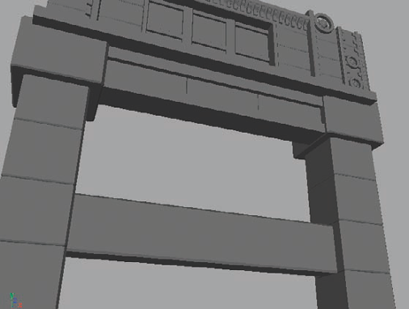
Duplicate the entire column and group it together (Ctrl+G). Move the new column 35 units over. This gives you the two sides of the base module (Figure 5.46).
Now to fill in the details between the two columns. These details can be whatever you like. Bricked walls, window paneling, or decorative molding designs. The sky's the limit. For a real project, you'd actually want a couple of different variations for this module so that the base isn't exactly the same all the way around.
Select one of the columns (not one of the bricks) and rotate it 90 degrees to lie horizontally. Select the front vertices and push them back, making the column half the depth. Place the horizontal column a little lower than halfway down the vertical columns and between the two.
This will be a horizontal border block between the windows and the bricks that you will add in later steps.
Select the top bricks of both columns and scale them up about 125 percent. This will give the two bricks more heft to act as support for the weight above them.
Create a few long, flat cubes along the top to create the beginning of a ledge. Have the top cube stick farther out than the ones below it for a tiered look.
Grab a brick and select the bottom vertices. Move them upward to flatten the brick and place a few along the top within the ledge pattern.
This ledge is for decorative purposes. You can adjust it to be whatever looks good to you. If you're following along with me, you should have something similar to Figure 5.47.
Just like the windows you created for the two window block modules (Modules 1 and 3), you can create another set of windows here. Think of these as storefront windows, so make them taller than the office/apartment windows you made previously.
Alternatively, you can create a different kind of wall here as well, as an addition if you want to give yourself more variation, which is, within reason, not a bad thing (Figure 5.48).
To fill in the space above the center dividing block, you can literally do whatever you'd like. I simply filled it with a brick pattern that will eventually be textured slightly differently than the rest of the area to give it some color variation.
At the top of the columns, below the large support blocks, add in some sort of decorative detail. I used the reference image and created a row of dentil molding with an upside-down omega shaped below it. Simple shapes can go a long way in architecture (Figure 5.49).


With that finished, you have created all 10 modules in this lesson. Please don't hesitate to create more if you like, to give yourself more variations. Keep in mind, however, that each additional module you make will add to the number of textures that will be needed for the final set of building modules. Also, in a real game project, you'll probably be creating a dozen different sets of modules, where each set can create another dozen different buildings. So, don't necessarily try to pack every idea you have into a single set. Save some for other building designs. Using this modular system, you'll be surprised just how quickly a city can come together.
But don't get me wrong, you're not done yet. These meshes were the high-resolution meshes! Now comes the low-resolution mesh building. But don't worry. These low-resolution meshes are pretty simple compared to what you just did. Speaking of what you just did, Figure 5.50 is an example of what can be created with the 10 modules you've made.

Given how detailed that last image looked, you'd be surprised at just how low the polycount of the low-resolution modules will be. Only if you're expecting your game to be like the game Champions Online and allow your players to literally climb tall buildings with Spider-Man style powers should your low-resolution meshes be very detailed.
Before beginning, create layers for each of your high-resolution modules. You can name them specific names for easy identification, such as
Window_Block_HiandRoof_Corner_Hi. The "Hi" designates them as the high-resolution versions of the modules. Assign each module's pieces to its respective layer.Hide all the modules except Module 1, the main window block.
As with the previous chapters, I find it easier to see what is going on by assigning a darker-colored material to the high-resolution mesh. The low-resolution mesh will have the original gray material so it stands out against the dark color for easy visibility.
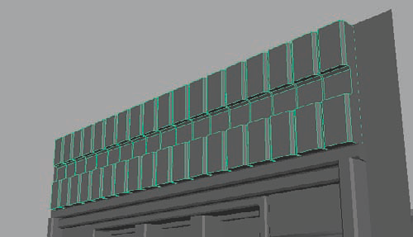
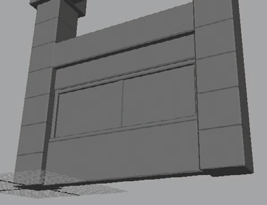
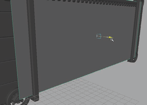
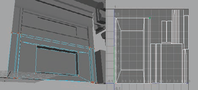
Create a plane that is 35 units wide and 15 units tall. Pull it out so that it is in front of the main window details. The upper ledge and side border shapes will still push through (Figure 5.51).
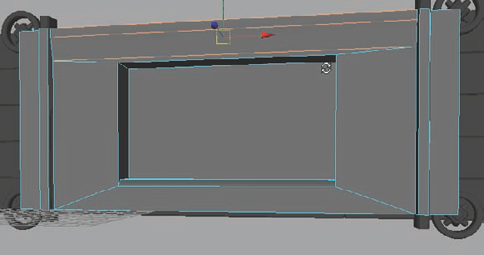
The goal is to add as few details as possible to cover the surface of the high-resolution mesh. For instance, for this window block, you can simply extrude in the window and cut in a few faces for the border and ledge and you are all ready to go (Figure 5.52).
Notice that the four corners of the low-resolution version of the window block go directly to the center of the round corner designs at each corner of the high-resolution mesh. When you duplicate and stack window blocks on top of each other and to their left and right, these details should tile together very nicely.
Note
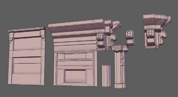
Repeat this process with each module, encompassing each high-resolution module with a lower resolution shell. You'll be surprised at just how easy this process can be for many of these modules, especially the columns. If you need a little extra help, though, you can consult the DVD video supplement, where I recorded each step. Eventually, you'll have something like Figure 5.53.
The next step is to UV map each module. Because each module is mostly rectangular, this process is much easier than some of your previous projects in this book.
Open the UV Texture Editor from under the Window menu. Select the low-resolution window block module and use the Automatic Mapping command found under the Create UVs menu. The result should be something similar to Figure 5.54.
You'll notice that it has the front of the module mostly put together, with a few of the other elements laid out to the side. With these kinds of shapes, it can be very easy to put the UV shells back together again. I'll show you how in these next steps.
In the UV Texture Editor (found under the Window menu), right-click and choose UV from the component selection marking menu that opens. This will turn on UV component mode and allow you to select UVs.
Select a UV from the main part of the mesh, the part containing the window opening. If your Automatic Mapping resulted in anything like mine did, you'll probably need to rotate it 90 degrees to make it right side up. In the UV Texture Editor's menus, choose Select → Select Shell. This will modify your selection to include all the UVs of the current shell you have selected. You can then use the Rotate Clockwise or Rotate Counterclockwise commands on the upper toolbar.
Once the UV shell is rotated uprightly (if it needed to be), you can right-click within the UV Texture Editor and choose Edge as your component selection. Select the top edge of the main UV shell and use the Move And Sew UV Edges command (found on the toolbar or under the editor's Polygons menu).
Do the same for the bottom edge of the shell. This will attach the UV shells on top and at the bottom of the main UV shell, merging them together properly.
Continue to do this for the top and bottom edges until every top and bottom UV shell is attached. You can then do the same for the left- and right-side UV shells.
Then you can select the edges that make up the window opening and use Move And Sew to join their respective UV shells together as well. Once you're done, you may need to manually move some UVs around to straighten them up if they came in at a strange angle. But you should eventually get something similar to Figure 5.55.
With so many pieces, it can be a big resource saver to have multiple objects share the same texture. So for this project, the two window block modules can share a texture, as can the ledge and corner ledge modules. The base and columns can share as well. Or they can be put together in some other combination. The goal is to make them fit together as well as possible with as little wasted, empty space as possible and with as little deformation as possible. To avoid deforming UV shells, you may have to break some shells up into separate pieces. In Figure 5.56, you can see that the 10 modules in this lesson can be laid out to share only four textures.


The textures can be handled many different ways, depending on what the player will be seeing. I hope that since I mention it so often, you can see how important it is to make certain that no time or energy is wasted, especially in a project as big as the construction of a city. So if the player will only see a building from the street level, the only vantage point that needs to look good is the player's vantage point.
The textures you make can be as detailed as you like. For mine, I'm going to make them simple, yet easy to read and understand the shapes. Feel free to follow along:
Just as you have in the previous chapters, you can use the Transfer Maps command to bake an Ambient Occlusion (AO) and normal map base texture for each of the four textures you UV mapped in the previous section (Figure 5.57).
If you are following along with me, you will begin with texturing the window blocks. Open Photoshop and open the baked window block AO texture (either your own or the one included on the DVD).
Note
From the DVD texture sources, open the concrete-looking texture called con004 (or use your own texture source that you like). Drag it into your Photoshop file and move its layer below the AO layer.
Change the AO layer's blending mode to Multiply. This will make the dark values of the AO render on top of whatever is below it.
Use the Free Transform tool (Ctrl+T) to resize the concrete image to fit on the window block module's portion of the texture space. You can rename the layer
Base, indicating that it is the base texture layer that other layers will build on.With the Base concrete layer selected, create a new Hue/Saturation adjustment layer above it. Change the color to a tan hue. If you are following along with me, I used a Hue value of −16 and a Saturation value of 68.
Next, create a Brightness/Contrast adjustment layer and increase both the brightness and contrast to give the surface a slightly more whitewashed look, as if it had been in the sun for years and years. I used a Brightness value of 15 and a Contrast value of 41. You'll have something similar to Figure 5.58.
Now you'll start adjusting the highs and lows of the surface and adding in some color variation. Create a new Hue/Saturation adjustment layer and increase the Lightness to 18.
This brightens the entire image, which you don't want. Select the adjustment layer's mask (the white box on the layer next to the image thumbnail) and invert it using the Ctrl+I keyboard shortcut.
This makes the layer mask black and thus hides the effect of the adjustment layer. You only want this layer's brightness to affect the raised portions of the window block.
Make white your selected brush color (press D to change your colors to the default white and black, if they aren't already). Select the brush tool (or the B shortcut key) and with the layer mask still selected, paint strokes along the raised sections of the window block, such as along the vertical divider blocks on the left and right as well as the ledges and supports, and anything else you may have in your image that represents a surface that is higher than the rest of the surface around it.
Create another Brightness/Contrast adjustment layer. Increase the contrast levels to add more readability to the image. I used a Brightness value of −5 and a Contrast value of 23.
Once again, invert the layer mask so that it is fully black. Then paint white strokes on the raised-up areas of the image.
Those two adjustment layers take care of the highs. Now you'll add the lows using shadow and lowlights.
Create a new Hue/Saturation adjustment layer and decrease the Lightness value to something like −30, darkening the image substantially. Once again, invert the mask to make it black and use a white brush to paint along the lower areas of the image. You can also paint a thin stroke along the brick borders to make them pop more. With the highs and lows painted on, you can see something like Figure 5.59 beginning to emerge.
Now the texture may look a little too whitewashed. It did in my case, so I went back and added one more adjustment layer. To do the same, create a Levels adjustment layer. Increase the lower range of the Input Levels to something like 80, leaving the mid and high input level values alone.
This time you won't invert the layer mask. Hold down the Control key and left-click the mask of one of the highlight adjustment layers from before. It doesn't matter which one. This will load the mask as a selection.
Select the layer mask for the new Levels adjustment layer. Choose black as your brush color and use the Fill command from under the Edit menu (or use the Alt+Delete shortcut key). This fills the selection with black and masks out the new Levels adjustment where the highlights are, making the Levels adjustment only affect the lower surface.


The windows of the building can be done lots of different ways. You could even let them be their own textures so that you could have many different varieties of windows to choose from. For this project, you'll keep it relatively simple and give all the windows just dark tinted glass. Of course, feel free to adjust this to your own liking.
Note
First, select the area that makes up the window frame. Open up a relatively simple metal texture, such as the Aluminum2 image from the DVD's source files.
With the metal image active, select all (Ctrl+A), copy (Ctrl+C), switch to your building texture with the window frame selection still active, and Paste Into (Shift+Ctrl+V).
The Paste Into command will paste the copied image into the active selection as its own layer, making the selection an automatic layer mask.
Press Ctrl+U to open the Hue/Saturation adjustment command and lower the Lightness value down to something like −70, making the window frame a dark metal like in Figure 5.60.
Select the window area again, but deselect the window frame. This leaves only the glass window panes left in your selection. Create a new layer and place it below the window frame layer. Fill the selection with black.
Ctrl+click the black windows to load them as a selection. Press Shift+Ctrl+V to use Paste Into once again, pasting the Aluminum texture into the glass window panes as their own layer. Change this new layer's Blending Mode to Linear Dodge, which creates a slight noise pattern.
Tune down the noise to be more subtle by lowering the layer's Opacity. This can be done to your preference. I lowered mine down to about 20 percent.
For the rest of the modules, you will literally do the same steps. You want all the modules to look consistent, so copy the adjustment layers you use for the first texture to use on the rest. The main difference you may want to make is adding some color variation for a few things, such as the decorative detail on the lower half of the small window block or the brick detail on the higher half of the base module. Once you're done you could have something similar to Figure 5.61.

With the modules completed, you can then go about creating your buildings. It's simply a matter of putting the modules together like a big jigsaw puzzle (Figure 5.62).
Note
Don't forget to break off the support strut to form Module 8!
With modular modeling, you can create a system of modules (also called tinker toys by certain aspects of the industry) to create practically any environmental structure. You could create a modular system of dungeons for a game with a medieval theme, a modular street system to go along with the city, or modular spans to create bridges of any length. There are many possibilities that modular building can afford an environment artist.
Next, let's cast some light on the situation. In the next chapter, you'll learn about illumination and objects that cast light. Campfires, spot lights, street lights, flashlights, lanterns—all sorts of objects may need to illuminate in some way. Turn the page to learn more!

