
CHAPTER 9
![]()
Get Oriented: Interacting with the Phone, Camera, GPS, and More
When you hold a modern mobile phone in your hands, you are a holding a sophisticated and complex system of sensors, hardware, and software—all working in harmony. It's easy to forget that just a few short years ago, each of these “parts” had its own API, and that it was up to the developer to figure out how to make it work.
With Windows Phone, the operating system provides a rich set of integrated APIs for you to use in your application when you want to know the device's location (GPS), orientation (compass, accelerometer and gyroscope), or surroundings (the camera). In this chapter, we'll cover how to use these sensors in your applications, as well as the best situations in which to use each of them.
Prior to the release of the 7.1 SDK, some of these sensors were unavailable. The first is access to the raw data feed from the camera. This enables key scenarios like image manipulation and augmented reality applications. Newer phones may also contain a gyroscope, and there's now an API for the compass that has been in every Windows Phone 7 since the beginning.
Tracking the Position of Your Device
There is much to be learned about a user's device from the data its sensors provide. Location is an obvious one, and it's important to know where the device is in order to give the user more information about where they currently are. Orientation of the device can be equally, if not more important, however. Using the compass, the accelerometer and the gyroscope, we can determine exactly which direction the phone is facing, its physical orientation in space, and rate at which it is rotating.
What makes the orientation sensors exceptional, however, is the Microsoft also provides us with the Motion class, which aggregates the data from all three of those sensors into one robust class that does a bunch of really complicated math on our behalf. We will cover each of these sensors, as well as the Motion class in this chapter.
Using Location Services
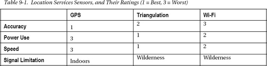
Windows Phone provides three ways to determine the location—the latitude and longitude—of a phone: GPS, mobile phone triangulation, and Wi-Fi. The first and most obvious choice is GPS. Every Windows Phone has a GPS chip, and for most purposes, it works incredibly well. That is, until you go inside a building.
Second, there's mobile phone triangulation. There are cell towers all over the place in metro areas, and by measuring the signal latency from the surrounding towers (and knowing their locations), you can make an educated estimation as to where the phone is, sometimes within as few as 50 feet.
Finally, there's Wi-Fi lookups. By connecting to a Wi-Fi access point, you have an IP address, and that IP address can be located with a reverse-IP lookup. This is not the most accurate process, but if you're trying to find the nearest McDonalds, it's almost certainly sufficient.
Each of these methods has its advantages and disadvantages, as shown in Table 9-1. GPS doesn't work well inside a building, it's relatively slow to get a signal, and it uses a lot of power, but it's extremely accurate. Triangulation is fast and low-power, but less accurate and really only works in populated areas. (There are not many cell towers in Antarctica or North Dakota, for example.) Wi-Fi is probably the least accurate, but again, it's fast.
Thankfully, for Windows Phone, we don't have to determine which service to use. In fact, we can't. Microsoft provides a single object for all of this data in Location Services. To show a device's location, you need a small bit of code in both your Xaml and C# files. Listing 9-1 shows the Xaml you'll need. We are adding three TextBlock values.
Listing 9-1. The Xaml Elements to Add to Your Location Services Project
<TextBlock Height="30" HorizontalAlignment="Left" Margin="12,101,0,0" Text="Latitude" VerticalAlignment="Top" />

<TextBlock Height="30" HorizontalAlignment="Left" Margin="12,239,0,0" Text="Longitude" VerticalAlignment="Top" />

<TextBlock Height="30" HorizontalAlignment="Left" Margin="12,376,0,0" Text="Status" VerticalAlignment="Top" />

<TextBlock Height="101" HorizontalAlignment="Left" Margin="12,137,0,0" x:Name="Latitude" Text="" VerticalAlignment="Top" Width="438" FontSize="72" />

<TextBlock Height="101" HorizontalAlignment="Left" Margin="12,275,0,0" x:Name="Longitude" Text="" VerticalAlignment="Top" Width="438" FontSize="72" />

<TextBlock Height="101" HorizontalAlignment="Left" Margin="12,406,0,0" x:Name="Accuracy" Text="" VerticalAlignment="Top" Width="438" FontSize="72" />

<TextBlock Height="30" HorizontalAlignment="Left" Margin="73,34,0,0" x:Name="Status" Text="Stopped" VerticalAlignment="Top" Width="306" TextAlignment="Center" />
1. Create a new Windows Phone Application project named “LocationSample.”
2. In MainPage.xaml, use the code from Listing 9-1 inside the default Grid named “ContentPanel.”
Now that we have a simple interface to work with, we can dive into the code to get our actual Location data. Listing 9-2 assumes that you want to get a new location every time the device moves, which is why we are using event handlers to get the data.
Listing 9-2. Detecting Location in Our Code-Behind File
using System;

using System.Device.Location;

using Microsoft.Phone.Controls;


namespace LocationSample

{

    public partial class MainPage : PhoneApplicationPage

    {

        GeoCoordinateWatcher gcw = new GeoCoordinateWatcher();


        public MainPage()

        {

            InitializeComponent();


            gcw.StatusChanged += new EventHandler<GeoPositionStatusChangedEventArgs>(gcw_StatusChanged);

            gcw.PositionChanged += new EventHandler<GeoPositionChangedEventArgs<GeoCoordinate>>(gcw_PositionChanged);

            gcw.Start();

        }


        void gcw_StatusChanged(object sender, GeoPositionStatusChangedEventArgs e)

        {

            Status.Text = e.Status.ToString();

        }


        void gcw_PositionChanged(object sender, GeoPositionChangedEventArgs<GeoCoordinate> e)

        {

            Latitude.Text = e.Position.Location.Latitude.ToString();

            Longitude.Text = e.Position.Location.Longitude.ToString();

            Accuracy.Text = e.Position.Location.HorizontalAccuracy.ToString();

        }


    }

}
In Listing 9-2, you can see that we instantiate a new GeoCoordinateWatcher object, and in our constructor method, MainPage(), we add two event handlers to that GeoCoordinateWatcher before we start it up. The GeoCoordinateWatcher class exposes the Location Services that we discussed earlier. Follow the next steps to use this in your project:
1. Replace the code in your MainPage.xaml.cs file with the code in Listing 9-2.
2. Run the application (F5).
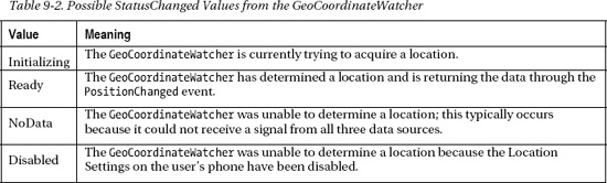
The first event handler in Listing 9-2, StatusChanged, is more for our purposes as a developer than for the end user. It gives us information about what the GeoCoordinateWatcher is doing. This is important because we need to know if it is looking for data, unable to find data, or actively returning data. The values it will return are shown in Table 9-2.
The second event handler, PositionChanged, is where the important data is kept. Each time that the GeoCoordinateWatcher detects that the user's position has changed, this event will fire again, returning a GeoCoordinate object for us to manipulate. The two primary properties of the GeoCoordinate object are a Timestamp object, so we know when we got the information from the device, and a Location object, which contains all of the specifics about the location of the device.
In our example, we retrieved the three most common Location values you'll use: Latitude, Longitude, and HorizontalAccuracy. While Latitude and Longitude are measures with which we're all familiar, HorizontalAccuracy is less so. It measures the GeoCoordinateWatcher's margin of error. HorizontalAccuracy is returned to you in a length of meters, and is meant to specify the radius of a circle that could be drawn around the lat/long point that was provided. This information should be conveyed to the user so that they're aware you're not 100 percent confident in their location. You should never expect a HorizontalAccuracy less than 4 to 5 meters, as commercial GPS devices are generally prevented from greater accuracy than that.
![]() Note: An important point to remember about Location Services is that there are specific rules about when you can and cannot use them in an application. This refers to Section 2.7 of the Application Certification Requirements for Windows Phone
Note: An important point to remember about Location Services is that there are specific rules about when you can and cannot use them in an application. This refers to Section 2.7 of the Application Certification Requirements for Windows Phone (http://msdn.microsoft.com/library/hh184843.aspx). You should take the time and care to read the entire document from start to finish.
It's also important to remember that your user must always be confident that Location services are only being used when they authorize them to be. This means that you need to provide a mechanism for them to turn Location services off (if applicable), or at the very least, the ability to opt-in every time you're going to gather that kind of data. You will fail Marketplace registration without adhering to these rules, so it's very important that you are aware of them.
You will discover that the emulator always defaults to Seattle, Washington, no matter where your computer is actually located. There is, however, a new tool in the emulator that makes it simple to change where the emulator thinks it is. To access it, open your Windows Phone emulator and press the chevron (>>) button that appears next to the emulator. Clicking the Location tab will take you to this feature, as shown in Figure 9-1.
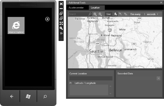
Figure 9-1. Windows Phone emulator location add-on
With this emulator add-on, you can use Bing Maps to specify your location, enter custom latitude and longitude values, or even record a trip to emulate data as the user drives across town or the country. To accomplish the trip emulation, you can click on the map in multiple places, and the individual locations will be added to a list in the Current Location panel of the tool. Once you have a list of locations, you click the Live button at the top of the map, which will enable the “Fire every 1 second” button to its right. You may change the duration to any number of seconds, and pressing the Play button will trigger the emulator to move through the list of locations you created, pausing for the duration of time you specified.
3. Click on the map a few times to add some locations to your map.
4. Click the Live button at the top of the tool.
5. Press the Play icon to have the tool feed each of your locations into your app on a one-second interval.
Now that you know how to determine the location of your device, the next piece of information we can use is the direction the device is heading from that location. We can accomplish this with the Compass sensor.
Using the Compass
The term compass is somewhat of a misnomer in mobile devices. There's not a little magnetic needle pointing north within your phone; instead we're actually accessing a device called a magnetometer (mag-neh-TOM-eh-ter). A magnetometer measures the strength and direction of a magnetic field, and it is the sensor we will use to determine the direction a device is pointing.
There are two primary values that we are interested in when we use the Compass API, MagneticHeading and TrueHeading. MagneticHeading contains the current heading of the device, measured in clockwise degrees, from the Earth's magnetic north. TrueHeading is measured in clockwise degrees from the Earth's geographic north (also referred to as True North). There are many publications dedicated to more specifics on these two locations, but the short explanation is that the true North Pole is a specific location where the Earth's axis of rotation meets Earth's surface. The magnetic north pole is the point on Earth's surface where Earth's magnetic field points vertically downwards. For real compass functionality, you'll want to use the MagneticHeading property.
To get started, we need to create a Xaml interface that shows compass data effectively. Listing 9-3 shows the elements you'll need to use.
Listing 9-3. The Xaml We Will Use to Show the Compass Data in an App
<TextBlock Height="30" HorizontalAlignment="Left"  Margin="20,73,0,0" Text="MAGNETIC" VerticalAlignment="Top" Foreground="White" FontSize="28" FontWeight="Bold"/>

<TextBlock Height="30" HorizontalAlignment="Right"  Margin="0,74,47,0" Text="TRUE" VerticalAlignment="Top" Foreground="Gray" FontSize="28" FontWeight="Bold"/>

<TextBlock Height="30" HorizontalAlignment="Left"  Margin="20,100,0,0" Name="magneticValue" Text="1.0" VerticalAlignment="Top" Foreground="White" FontSize="28" FontWeight="Bold" Width="147" TextAlignment="Center" />

<TextBlock Height="30" HorizontalAlignment="Right"  Margin="0,100,20,0" Name="trueValue" Text="1.0" VerticalAlignment="Top" Foreground="Gray" FontSize="28" FontWeight="Bold" Width="123" TextAlignment="Center" />

<TextBlock Height="30" HorizontalAlignment="Left"  Margin="20,140,0,0" Name="xBlock" Text="X: 1.0" VerticalAlignment="Top" Foreground="Red" FontSize="28" FontWeight="Bold"/>

<TextBlock Height="30" HorizontalAlignment="Center"  Margin="0,140,0,0" Name="yBlock" Text="Y: 1.0" VerticalAlignment="Top" Foreground="Green" FontSize="28" FontWeight="Bold"/>

<TextBlock Height="30" HorizontalAlignment="Right"  Margin="0,140,20,0" Name="zBlock" Text="Z: 1.0" VerticalAlignment="Top"  Foreground="Blue" FontSize="28" FontWeight="Bold"/>

<Line x:Name="magneticLine" X1="240" Y1="350" X2="240" Y2="270" Stroke="White" StrokeThickness="4"></Line>
Figure 9-2 shows what this interface will look like. To add this code to your application, take the following steps:
6. Create a new Windows Phone Application project named “CompassSample.”
7. Like our Location example earlier, add the contents of Listing 9-3 to the ContentPanel Grid that Visual Studio created by default.
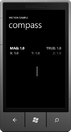
Figure 9-2. The user interface for our compass application
To access MagneticHeading and TrueHeading values on a Windows Phone device, we need to create and start a new Compass object, and then monitor an event handler for the values we need. Every Windows Phone has a compass, but only those that have been upgraded to Windows Phone 7.5 actually have the Compass API. Because of this, we'll also need to check to make sure we have access to this data. The code to do this is shown in Listing 9-4. Please note that we need a using statement for Microsoft.Devices.Sensors to access this sensor.
Listing 9-4. The C# We Will Use in Our MainPage.xaml.cs File for the Compass
using System;

using Microsoft.Phone.Controls;

using Microsoft.Devices.Sensors;

using Microsoft.Xna.Framework;


namespace CompassSample

{

        public partial class MainPage : PhoneApplicationPage

        {

                Compass compass;
        public MainPage()

        {

            InitializeComponent();


            if (Compass.IsSupported)

            {

                compass = new Compass();

                compass.TimeBetweenUpdates = TimeSpan.FromMilliseconds(1);

                compass.CurrentValueChanged += new EventHandler<SensorReadingEventArgs<CompassReading>>(compass_CurrentValueChanged);

                compass.Start();

            }

        }


        void compass_CurrentValueChanged(object sender, SensorReadingEventArgs<CompassReading> e)

        {

            Dispatcher.BeginInvoke(() => UpdateUI(e.SensorReading));

        }


        private void UpdateUI(CompassReading compassReading)

        {

            magneticValue.Text = compassReading.MagneticHeading.ToString("0.00");

            trueValue.Text = compassReading.TrueHeading.ToString("0.00");


            magneticLine.X2 = magneticLine.X1 - (200 * Math.Sin(MathHelper.ToRadians((float)compassReading.MagneticHeading)));

            magneticLine.Y2 = magneticLine.Y1 - (200 * Math.Cos(MathHelper.ToRadians((float)compassReading.MagneticHeading)));


            xBlock.Text = "X: " + compassReading.MagnetometerReading.X.ToString("0.00");

            yBlock.Text = "Y: " + compassReading.MagnetometerReading.Y.ToString("0.00");

            zBlock.Text = "Z: " + compassReading.MagnetometerReading.Z.ToString("0.00");

        }

        }

}
Much like the Location example in Listing 9-2, you will need a new Compass object created at the top of your code. In the initialization method this time, we need to check to make sure that the Compass sensor is supported. We do this with the Compass.IsSupported boolean check. Windows Phones running the original operating system do not have the ability to access the Compass sensor, and will result in an error if we try. To get this code into your project, the following are the next steps:
8. Replace the code in your MainPage.xaml.cs file with the contents of Listing 9-4.
9. Run your project in the emulator (F5).
10. Be disappointed that the emulator doesn't support the Compass.
Yes, step 5 is utter disappointment. The emulator does not support the compass sensor. It is our hope that in the future, there will be a gyroscope and compass tool (like the Accelerometer and Location tools we have now), but for now, you will need to test this application on a real device.
There is one event handler that we will use regularly with the Compass, CurrentValueChanged. As with the other sensors we'll cover in this chapter, you should notice that we actually pass our CompassReading data to a separate thread so that we don't freeze or interrupt the user interface thread. This is done using the Dispatcher.BeginInvoke() method, which moves the processing of our data to a separate thread.
In our CompassReading data, we get a great number of data points, but the most common ones are used in our example. MagneticHeading and TrueHeading are covered earlier in this section, but you can see that we also have access to an X, Y, and Z value. These are the raw Magnetometer readings, measured in microteslas (mT), which are a measurement of magnetic field strength. As an example, a common refrigerator magnet is around 5 mT, while a MRI (magnetic resonance imaging) generally measures around 3,000 mT. The values you will get from the earth's magnetic poles can vary greatly depending on the device's location, so make sure that you understand these variances as you use this sensor. Wikipedia has an excellent article on this topic; you can find it at http://en.wikipedia.org/wiki/Earth%27s_magnetic_field.
We have also created a Line as part of our user interface, and in the code in Listing 9-4, you can see that we are using the MagneticHeading to give that line a direction to point.
As we mentioned earlier, make sure you are aware of the possibility that other magnetic fields can and will interfere with the readings of the compass and its magnetometer, which shouldn't be trusted as 100 percent accurate all of the time. If you are building a true compass application, it might be best to verify your readings against a recent set of GPS locations, to verify that the user is actually traveling the direction that your compass is suggesting. Otherwise, you are going to be getting your customers lost, and that's probably not a great user experience.
At this point, we've covered how to determine the location and heading of our user's device. The rest of this section will focus on the orientation and rotation of a Windows Phone, starting with the accelerometer.
Using the Accelerometer
An accelerometer in Windows Phone is a sensor that measures the acceleration of the device on three axes (X, Y, Z) relative to freefall perpendicular to the earth, as illustrated by Figure 9-3. In addition to a timestamp, the values are expressed in G-forces (1G = 9.81 m/s2or as you may have learned in school, 32 feet per second per second). What this means is that if the phone is laying face-up on a perfectly flat surface, the Z axis would read -1.0, and the other two axes would read zero. To help illustrate this concept, take a look at Figure 9-3. If the phone is sitting still on a flat table, the force of Earth's gravity is pulling the accelerometer downwards on the Z axis, resulting in a -1.0 value. Turning the phone face down would turn the Z axis reading to a positive value. The important lesson here is that the “positive” directions for the phone are when it is being pulled forward, up, or right. Backward, left, and down will all result in a negative value.
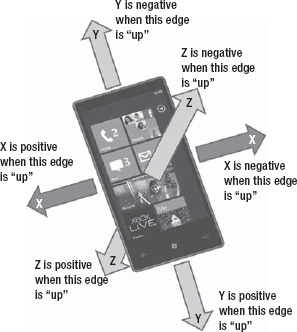
Figure 9-3. An illustration of the X, Y, and Z axes of the accelerometer
Thankfully, getting data from this sensor is very straightforward. The only real challenge we face with this is that we want to keep the process thread-safe. This means passing our accelerometer actions to a separate thread, so that we don't impact the UI thread and lock it up while we acquire the data.
Listing 9-5 shows the Xaml we will need for this simple example. We have a few TextBlock elements that will display the X, Y, and Z axis values from the accelerometer. Figure 9-4 shows what this interface will look like.
Listing 9-5. A Simple Xaml Interface for Our Accelerometer Application
<TextBlock Text="X = " FontSize="60" Margin="0,0,0,0" />

<TextBlock Text="Y = " FontSize="60" Margin="0,100,0,0" />

<TextBlock Text="Z = " FontSize="60" Margin="0,200,0,0" />

<TextBlock x:Name="xValue" FontSize="60" Margin="110,0,0,0" />

<TextBlock x:Name="yValue" FontSize="60" Margin="110,100,0,0" />

<TextBlock x:Name="zValue" FontSize="60" Margin="110,200,0,0" />
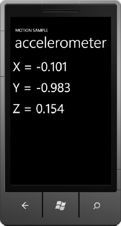
Figure 9-4. Our simple accelerometer application interface
To build this application, start with the following:
11. Create a new Windows Phone Application called “AccelerometerSample.”
12. Add the Xaml found in Listing 9-5 to the ContentPanel Grid in your MainPage.xaml file.
Listing 9-6 shows the entirety of our MainPage.xaml.cs file for this example. Also notice that we had to add a new reference to Microsoft.Devices.Sensors to get access to the accelerometer.
Listing 9-6. Using C# to Access the Accelerometer
using System;

using Microsoft.Phone.Controls;

using Microsoft.Devices.Sensors;


namespace AccelerometerSample

{

    public partial class MainPage : PhoneApplicationPage

    {
        Accelerometer accelerometer;

        public MainPage()

        {

            InitializeComponent();


            accelerometer = new Accelerometer();

            accelerometer.CurrentValueChanged += new EventHandler<SensorReadingEventArgs<AccelerometerReading>>(accelerometer_CurrentValueChanged);

            accelerometer.Start();

        }


        void accelerometer_CurrentValueChanged(object sender, SensorReadingEventArgs<AccelerometerReading> e)

        {

            Dispatcher.BeginInvoke(() => UpdateUI(e));

        }


        void UpdateUI(SensorReadingEventArgs<AccelerometerReading> e)

        {

            xValue.Text = e.SensorReading.Acceleration.X.ToString("0.000");

            yValue.Text = e.SensorReading.Acceleration.Y.ToString("0.000");

            zValue.Text = e.SensorReading.Acceleration.Z.ToString("0.000");

        }

    }

}
In order to use this in your project, follow the remaining steps.
13. Replace the code in your MainPage.xaml.cs file with the C# in Listing 9-6.
14. Run your project in the emulator (F5).
When you try to run the code in Listing 9-6 in the emulator, you'll notice that you get a value of -1.0 from the Y axis, and zeroes on the others. This is the default value for the emulator, and indicates that the “device” is sitting perfectly vertical. To get actual values in the emulator, pick up your computer and shake it. Okay, don't actually do that.
You have the following options for getting real data while you're debugging:
- Deploy your app to an actual Windows Phone device
- Use the new emulator add-on
- Use one of many third-party libraries that provide ways to simulate accelerometer data
We're going to cover the simplest of those solutions, the emulator add-on. To access it, you can open the Additional Tools from the emulator again, and click the Accelerometer tab (it is selected by default.) It costs nothing to get and is surprisingly fun to use. All you need to do is move the small circle around inside the tool, and the phone emulator will appear to rotate in 3D space. It also provides the ability to feed in random shake data, as well as reset the device to standard orientations like “Portrait Standing” and “Landscape Flat,” as shown in Figure 9-5.
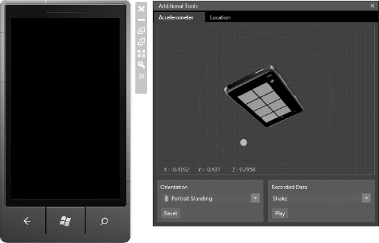
Figure 9-5. Using the Accelerometer tool in the Windows Phone emulator
The accelerometer gives us a great deal of information about the gravitational forces that are being exerted on the device. In the next section, we're going to look at its sister, the gyroscope, which gives us information about rotational velocity of the device.
Using the Gyroscope
The gyroscope sensor is as easy to use as the accelerometer, but we don't get the benefit of any the additional tools in the emulator. A gyroscope measures rotational velocity of the device on the same three axes as the accelerometer: X, Y, and Z. The data you receive measures this velocity in radians per second.
This means that you can more accurately, and more smoothly measure the current orientation of the device. This will become especially handy when you build applications that perform augmented reality. In most cases, however, you're probably not going to be accessing the gyroscope by itself. There are a couple of reasons for this:
- Not all Windows Phones will have a gyroscope. In fact, only phones that come out after the Mango release will be capable of having a gyroscope, and it is still an optional piece of hardware.
- Microsoft has created a Motion API that combines the data from the Accelerometer, the Compass, and the Gyroscope into one class that we can use more effectively.
However, in case you do need to use the gyroscope independent of the Motion API, you can use the sample code in Listings 9-7 and 9-8.user interface
Listing 9-7. A Xaml Interface to View Our Gyroscope Data
<TextBlock Height="30" HorizontalAlignment="Left"  Margin="20,100,0,0" Name="xTextBlock" Text="X: 1.0" VerticalAlignment="Top" Foreground="Red" FontSize="28" FontWeight="Bold"/>

<TextBlock Height="30" HorizontalAlignment="Center"  Margin="0,100,0,0" Name="yTextBlock" Text="Y: 1.0" VerticalAlignment="Top" Foreground="Yellow" FontSize="28" FontWeight="Bold"/>

<TextBlock Height="30" HorizontalAlignment="Right"  Margin="0,100,20,0" Name="zTextBlock" Text="Z: 1.0" VerticalAlignment="Top"  Foreground="Blue" FontSize="28" FontWeight="Bold"/>

<Line x:Name="xLine" X1="240" Y1="350" X2="340" Y2="350" Stroke="Red" StrokeThickness="4"></Line>

<Line x:Name="yLine" X1="240" Y1="350" X2="240" Y2="270" Stroke="Yellow" StrokeThickness="4"></Line>

<Line x:Name="zLine" X1="240" Y1="350" X2="190" Y2="400" Stroke="Blue" StrokeThickness="4"></Line>

<TextBlock Height="30" HorizontalAlignment="Center" Margin="6,571,6,0" Name="statusTextBlock" Text="TextBlock" VerticalAlignment="Top" Width="444" />
In order to use the code in Listing 9-7, follow these next steps.
15. Create a new Windows Phone Application project called “GyroscopeSample.”
16. Add the code in Listing 9-6 into the ContentPanel Grid in your MainPage.xaml file.
The interface we are building will look like the image in Figure 9-6.
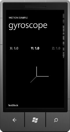
Figure 9-6. The user interface for our gyroscope application
In order to access the gyroscope directly, you should always wrap your code with a check to determine that the device supports the gyroscope sensor. As we did with the Accelerometer, we set up an event handler for when the values of the Gyroscope change, pass that data to a separate thread, and then update the data in our user interface as shown in Listing 9-8.
Listing 9-8. Using C# to Access the Gyroscope Sensor
using System;

using Microsoft.Phone.Controls;

using Microsoft.Devices.Sensors;

using Microsoft.Xna.Framework;


namespace GyroscopeSample

{

    public partial class MainPage : PhoneApplicationPage
    {

        Gyroscope g;


        public MainPage()

        {

            InitializeComponent();


            if (Gyroscope.IsSupported)

            {

                g = new Gyroscope();

                g.TimeBetweenUpdates = TimeSpan.FromMilliseconds(20);

                g.CurrentValueChanged += new EventHandler<SensorReadingEventArgs<GyroscopeReading>>(g_CurrentValueChanged);

                g.Start();

            }

        }


        void g_CurrentValueChanged(object sender, SensorReadingEventArgs<GyroscopeReading> e)

        {

            Dispatcher.BeginInvoke(() => UpdateUI(e.SensorReading));

        }


        private void UpdateUI(GyroscopeReading gyroscopeReading)

        {

            statusTextBlock.Text = "getting data";


            Vector3 rotationRate = gyroscopeReading.RotationRate;


            // Show the numeric values.

            xTextBlock.Text = "X: " + rotationRate.X.ToString("0.00");

            yTextBlock.Text = "Y: " + rotationRate.Y.ToString("0.00");

            zTextBlock.Text = "Z: " + rotationRate.Z.ToString("0.00");


            // Show the values graphically.

            xLine.X2 = xLine.X1 + rotationRate.X * 200;

            yLine.Y2 = yLine.Y1 - rotationRate.Y * 200;

            zLine.X2 = zLine.X1 - rotationRate.Z * 100;

            zLine.Y2 = zLine.Y1 + rotationRate.Z * 100;

        }

    }

}
To use the code from Listing 9-8 in your sample application, take the following steps:
17. Replace the contents of your MainPage.xaml.cs file with the code in Listing 9-8.
18. Run your application (F5).
19. Realize that the gyroscope is also not supported by the emulator.
To explain Listing 9-8 clearly, we create a new Gyroscope object first. After checking to make sure that the Gyroscope is supported with the Gyroscope.IsSupported boolean value, we create an event handler for CurrentValueChanged. The Gyroscope, like the Compass, allows our event handler method to fire every time the Gyroscope detects a new value, keeping the TimeBetweenUpdates value in consideration. In our example, we will get updates no faster than every 20 milliseconds. We gather each of the X, Y, and Z values from the Vector3 value RotationRate. We are just displaying the data values in TextBlocks, but not doing anything useful with the data. To do something more interesting, we created an interface that visually represents that data (shown in Figure 9-7).
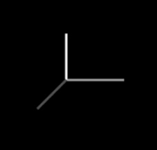
Figure 9-7. A closer look at the data visualization of the Gyroscope
If you imagine each line segment to represent a different data point (the horizontal line is X, the vertical line is Y, and the diagonal line is the Z axis. You could then manipulate the lengths of these lines to represent the rotational velocity of the device. Each of these calculations will extend the length of their respective lines, giving you a very illustrative example of what types of rotation your device is experiencing. While this is handy, you'll find that using the Motion API will give you this information as well, in addition to several other calculations.
Using the Motion API
Bringing the Accelerometer, Gyroscope, and Compass together, the Motion class allows you to detect a great number of motion values, like pitch, yaw, and roll. In flight dynamics, these are the three critical parameters used to determine the orientation of an aircraft in relation to its center of gravity. Each term refers to rotation about their respective axes. Figure 9-8 is a simple illustration, in relation to an airplane.
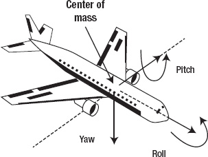
Figure 9-8..An illustration of pitch, yaw, and roll in aviation.
Simplistically, roll will move a given wing up or down, pitch will move the nose up or down, and yaw will move the nose right or left, as shown in Figure 9-8.
You can see that the arrows that extend from the center of the airplane are exactly the same lines that we created when we were looking at the gyroscope, X, Y, and Z. In this case, however, we also have the ability to measure the rotation around those axes, not just in relation to the center of the phone.
In our code example for the Motion class, you can use the code in Listing 9-9 to place a star in the middle of our page, and have it rotate as the Motion object detects changes to the orientation of the device. We will have it move in relation to the yaw value, which will make the star appear to remain stationary as we rotate the device. By rotating it on a flat plane, you will be able to see the orientation of the star remain static at all times. To build this interface, use the code in Listing 9-9. In previous examples, we have only included the Xaml that you need to add to your ContentPanel Grid control. This sample shows the contents of the MainPage.xaml file to show a new namespace we're using to create the star shape.
Listing 9-9. The User Interface for Our Motion Class Application
<phone:PhoneApplicationPage

    xmlns="http://schemas.microsoft.com/winfx/2006/xaml/presentation"

    xmlns:x="http://schemas.microsoft.com/winfx/2006/xaml"

    xmlns:phone="clr-namespace:Microsoft.Phone.Controls;assembly=Microsoft.Phone"

    xmlns:shell="clr-namespace:Microsoft.Phone.Shell;assembly=Microsoft.Phone"

    xmlns:d="http://schemas.microsoft.com/expression/blend/2008"

    xmlns:mc="http://schemas.openxmlformats.org/markup-compatibility/2006"

    xmlns:es="clr-namespace:Microsoft.Expression.Shapes;assembly=Microsoft.Expression.Drawing"

    x:Class="MotionSample.MainPage"

    FontFamily="{StaticResource PhoneFontFamilyNormal}"

    FontSize="{StaticResource PhoneFontSizeNormal}"

    Foreground="{StaticResource PhoneForegroundBrush}"

    SupportedOrientations="Portrait" Orientation="Portrait"

    mc:Ignorable="d" d:DesignHeight="768" d:DesignWidth="480"

    shell:SystemTray.IsVisible="True">
    <Grid x:Name="LayoutRoot" Background="Transparent">

        <Grid.RowDefinitions>

            <RowDefinition Height="Auto"/>

            <RowDefinition Height="*"/>

        </Grid.RowDefinitions>


        <StackPanel x:Name="TitlePanel" Grid.Row="0" Margin="12,17,0,28">

            <TextBlock x:Name="ApplicationTitle" Text="MOTION SAMPLE" Style="{StaticResource PhoneTextNormalStyle}"/>

            <TextBlock x:Name="PageTitle" Text="motion" Margin="9,-7,0,0" Style="{StaticResource PhoneTextTitle1Style}"/>

        </StackPanel>


        <Grid x:Name="ContentPanel" Grid.Row="1" Margin="12,0,12,0">

                <es:RegularPolygon x:Name="Star" InnerRadius="0.47211" Margin="100,175,100,175" PointCount="5" Stretch="Fill" Stroke="White" UseLayoutRounding="False" StrokeThickness="6">

                        <es:RegularPolygon.Fill>

                                <SolidColorBrush Color="{StaticResource PhoneAccentColor}"/>

                        </es:RegularPolygon.Fill>

                <es:RegularPolygon.RenderTransform>

                    <RotateTransform CenterX="100" CenterY="128"></RotateTransform>

                </es:RegularPolygon.RenderTransform>

                </es:RegularPolygon>


            <TextBlock x:Name="yawValue" Text="YAW = 34.567" FontSize="40" Width="400" Height="100" TextAlignment="Center" Margin="28,503,28,4" />

        </Grid>

    </Grid>

</phone:PhoneApplicationPage>
Take the following steps to start building a sample application that uses the Motion class:
20. Create a new Windows Phone Application project named “MotionSample.”
21. Replace the code in MainPage.xaml with the code in Listing 9-9.
You may notice that to render our Star polygon shape, we utilized a namespace specific to Expression Blend: Microsoft.Expression.Shapes. By using this namespace, you can create polygons with many different shapes without having to do the complicated math that is generally required to create something like a star (shown in Figure 9-9).
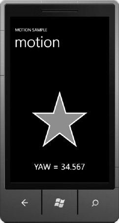
Figure 9-9. Our user interface for the Motion class applicationstar
The es:RegularPolygon element allows you to specify a PointCount for our shape. In the case of five points, it looks like a traditional solid pentagram. Adding or removing points will result in a star shape with any number of points from three to eighty. Anything more than about eighty continues to look the same, while anything with three or fewer points looks like the center of the Mercedes-Benz logo. For you Star Wars fans, it resembles the Empire's Imperial Shuttle as well (shown in Figure 9-10.)

Figure 9-10. A polygon shape with three or fewer points specified.
To make this Motion app work, we need to access the Motion class in our code-behind file. Listing 9-10 shows this code.
Listing 9-10. Using C# to Access the Motion Class
using System;

using System.Windows.Media;

using Microsoft.Phone.Controls;

using Microsoft.Devices.Sensors;

using Microsoft.Xna.Framework;


namespace MotionSample

{

    public partial class MainPage : PhoneApplicationPage

    {

        Motion motion;


        public MainPage()

        {

            InitializeComponent();


            if (Motion.IsSupported)

            {

                motion = new Motion();

                motion.TimeBetweenUpdates = TimeSpan.FromMilliseconds(20);

                motion.CurrentValueChanged += new EventHandler<SensorReadingEventArgs<MotionReading>>(motion_CurrentValueChanged);

                motion.Start();

            }

        }
        void motion_CurrentValueChanged(object sender, SensorReadingEventArgs<MotionReading> e)

        {

            Dispatcher.BeginInvoke(() => UpdateUI(e.SensorReading));

        }


        private void UpdateUI(MotionReading e)

        {

            ((RotateTransform)Star.RenderTransform).Angle = MathHelper.ToDegrees(e.Attitude.Yaw);

            yawValue.Text = e.Attitude.Yaw.ToString();

        }

    }

}
To use this code in your application, you need to do the following:
22. Replace the code in your MainPage.xaml.cs file with the code in Listing 9-10.
23. Run your application (F5).
24. Discover, for the third time in this chapter, that the emulator does not currently support this sensor.
The Motion API works very similarly to the Accelerometer, Compass and Gyroscope objects. We need to create a new instance of a Motion object, and then create a new CurrentValueChanged event handler for it. Each time new data is received, this event receives a great deal of rich data. If you're investing in understanding the math that the Motion class is producing, you should further explore what the MotionReading class has to offer. The following is a short list:
Attitude: Pitch, roll, and yaw; measured in radians.DeviceAcceleration: Measures the device's acceleration on the X, Y, and Z axes.DeviceRotation: Measures the device's rotation on the X, Y, and Z axes.Gravity: Measures the gravity vector of the device.
In our example, we are changing the angle of rotation of our star, basing it on the yaw value of the phone. Depending on the orientation of the phone, however, that value can vary significantly. For example, when the phone is faceup, the star moves at a reasonable speed when you tilt the device. However, if you hold the phone facedown and try similar movements, the star will appear to move twice as fast. This is because the calculation for yaw now includes a positive number instead of a negative one. Reference our discussion of the Accelerometer values for more information about how these positive and negative values come to be.
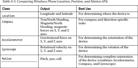
In this section, we've covered several powerful sensors available in Windows Phone devices. Table 9-3 reviews each of the sensors, their outputs, and what you will generally use each of them for in your applications.
Accessing Raw Camera Data
Above and beyond the camera tasks (see Chapter 7), we have the ability to tap into the raw camera feed from the device. This is handy for several reasons: we can grab both still images and video from this feed, as well as add our own data to the display for augmented reality-type applications. Combining the raw video feed with the Motion data we just learned to capture allows us to render objects, text, and other information into the real-time view of the user's camera. While a full Augmented Reality (AR) example is well beyond the scope of this book, Microsoft offers an excellent tutorial on the MSDN web site at http://msdn.microsoft.com/library/hh202984(v=VS.92).aspx.
In our example for this section, we will show you how to focus the camera and capture both photos and video from the raw camera feed. First, we need to display the camera's raw data on the screen of the device, as shown in Figure 9-11. We can do this by setting a VideoBrush as the Fill property of a rectangle, as shown in Listing 9-11.
Listing 9-11. Building the User Interface for a Camera Application
<Rectangle x:Name="ViewBox" Height="460" Margin="-22,-1,-131,148">

        <Rectangle.Fill>

                <VideoBrush x:Name="CameraSource" />

        </Rectangle.Fill>

        <Rectangle.RenderTransform>

                <RotateTransform Angle="90" CenterX="240" CenterY="240" />

        </Rectangle.RenderTransform>

</Rectangle>

<Button Foreground="Green" BorderBrush="Green" Content="Capture" Height="72" HorizontalAlignment="Left" Margin="6,535,0,0" Name="CaptureButton" VerticalAlignment="Top" Width="160" Click="CaptureButton_Click" />
To use the code in Listing 9-11, follow the next set of steps.
25. Create a new Windows Phone Application project named “CameraSample.”
26. Add the Xaml in Listing 9-11 to the ContentPanel Grid in your MainPage.xaml file.
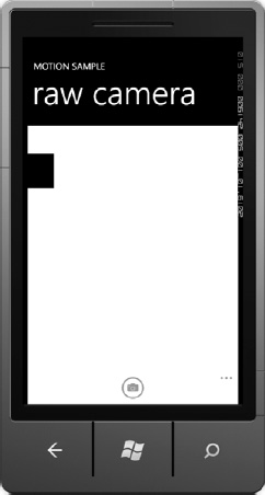
Figure 9-11. Our camera interface in the Windows Phone emulator
As you can see in the Xaml in Listing 9-11, we've added a Rectangle to the default page template, and defined its Fill property to be a VideoBrush named “CameraSource.” You should also notice the RenderTransform we applied to the Rectangle. By rotating it 90 degrees, we are actually accommodating the fact that the cameras are mounted in the phone with a Landscape orientation. In our C# code-behind, we need to assign our camera data to that VideoBrush. We do this by creating a PhotoCamera object named “camera” and setting the source of our VideoBrush to be that PhotoCamera object (shown in Listing 9-12).
Listing 9-12. Accessing the Raw Camera Feed in Our Code-Behind File
using System;

using System.Windows;

using Microsoft.Phone.Controls;

using Microsoft.Devices;
using Microsoft.Xna.Framework.Media;


namespace Day7_RawCamera

{

        public partial class MainPage : PhoneApplicationPage

        {

                PhotoCamera camera;

                MediaLibrary library = new MediaLibrary();


                // Constructor

                public MainPage()

                {

                        InitializeComponent();

                        if (PhotoCamera.IsCameraTypeSupported(CameraType.FrontFacing))

                                camera = new PhotoCamera(CameraType.FrontFacing);

                        else

                                camera = new PhotoCamera(CameraType.Primary);

                        camera.CaptureImageAvailable += new System.EventHandler<ContentReadyEventArgs>(camera_CaptureImageAvailable);

                        CameraSource.SetSource(camera);

                }


                private void CaptureButton_Click(object sender, System.Windows.RoutedEventArgs e)

                {

                        try { camera.CaptureImage(); }

                        catch (Exception ex) { Dispatcher.BeginInvoke(() => MessageBox.Show(ex.Message)); }

                }


                void camera_CaptureImageAvailable(object sender, ContentReadyEventArgs e)

                {

                        Dispatcher.BeginInvoke(() => ThreadSafeImageCapture(e));

                }


                void ThreadSafeImageCapture(ContentReadyEventArgs e)

                {

                        library.SavePictureToCameraRoll(DateTime.Now.ToString() + ".jpg", e.ImageStream);

                }

        }

}

To finish this sample camera application, follow the remaining steps.
27. Replace the contents of your MainPage.xaml.cs file with the code in Listing 9-11.
28. Run your application (F5).
29. On the emulator, you'll see the familiar white box with the small black square. On a real device, you'll see whatever the camera sensor sees.
Looking at Listing 9-12, we feed the raw data from the camera directly into the Rectangle without any complicated code maneuvers. In the code-behind, we create a new PhotoCamera object, and set the source (SetSource) of the VideoBrush equal to the new PhotoCamera object we created.
If you run our example code in the emulator, you're going to find the same type of output that you saw when you used the camera-related Launchers and Choosers (see Chapter 7). It will appear to be a white box with a black box traveling clockwise around the outside (shown in Figure 9-11). On an actual device, however, you will see the raw camera feed.
To grab a still image, we used the CaptureImage() method of the PhotoCamera class. For the simple purposes of our application, we're using the ApplicationBar to provide our buttons.
You will see that we are using the CaptureImageAvailable event handler on our PhotoCamera object. There is also a CaptureThumbnailAvailable event that you can use to grab a thumbnail of the image for gallery purposes. This is a nice additional feature, because it means you don't have to load each potentially giant image at a smaller size.
You should also notice that you must move the image capture to a separate thread. Leaving both the raw feed and the CaptureImage() method on the same thread will always result in an UnauthorizedAccessException, which means that you're trying to access data across different threads.
As you can see, we can call the CaptureImage() method, which, when completed, will fire the CaptureImageAvailable event handler. We pass the result of the event handlers to a separate thread, and gather the photo results. It's a very straightforward process that makes it easy to capture data from the raw video feed. This becomes especially handy when you want more than one image to be taken. For example, calling the CaptureImage() method once every second would provide an excellent way to capture a child running across your backyard. Or perhaps that amazing touchdown. There are tons of possibilities; it's up to you to be creative with these tools and come up with that next amazing app.
Summary
After reading this chapter, your mind should have been flooded with dozens of ideas for how you can improve your application idea. One recommendation we can offer you is that making an application location-aware makes it better. No matter your app, adding location data can make it better. Making a game? Play with other people that are nearby. Building a home-inventory app? Recommend nearby homeowner's insurance agents when they upload valuable property. Take the time as you're building your application to think about how you can incorporate a user's location into making your application richer.
As for the other sensors, if they don't have a direct purpose in your app, use that information for creating “Easter eggs” instead. The user turns the phone upside down? Give them a funny response that lets them know you noticed.
By using the orientation sensors with the camera, we end up with the opportunity to build augmented reality applications. Imagine holding your phone up in a crowded holiday parking lot, and using it like a viewfinder. When you point your phone in the direction of your car, there's a giant blue arrow pointing down from the sky to the top of your car. All you would need to do at this point is walk towards the arrow to find your vehicle. This is an example of augmented reality. There are an infinite number of ways we could enhance a user's view on the world around them by combining these technologies.
One great use of the accelerometer that we've seen was in a cycling application. The primary focus of the application was to track where a user was riding his bicycle. As a safety feature, you could enter an emergency phone number. If the application recognized an uncomfortably fast stop, followed by very little movement, it would automatically text the emergency phone number with the GPS coordinates of the device. Following that, it would prompt the phone to dial 911. This is an amazing use of both location and accelerometer data that will ultimately help to keep cyclists safer. Your app can use it too.