
7
Processor and Memory Architectures
This chapter takes a deeper look at modern processor architectures, specifically the von Neumann, Harvard, and modified Harvard variants, as well as the computing domains in which each architecture tends to be applied. The concepts and benefits of paged virtual memory, employed extensively in consumer and business computing and in portable smart devices, are also introduced. We will examine the practical details of memory management in the real-world context of Windows NT and later Windows versions. The chapter concludes with a discussion of the features and functions of the memory management unit.
After completing this chapter, you will have learned the key features of modern processor architectures and the use of physical and virtual memory. You will also understand the benefits of memory paging and the functions of the memory management unit.
This chapter covers the following topics:
- The von Neumann, Harvard, and modified Harvard architectures
- Physical and virtual memory
- Paged virtual memory
- Memory management unit
Technical requirements
The files for this chapter, including the answers to the exercises, are available at https://github.com/PacktPublishing/Modern-Computer-Architecture-and-Organization-Second-Edition.
The von Neumann, Harvard, and modified Harvard architectures
In earlier chapters, we touched briefly on the history and modern applications of the von Neumann, Harvard, and modified Harvard processor architectures. In this section, we’ll examine each of these configurations in greater detail and look at the computing applications in which each of these architectures tends to be applied.
The von Neumann architecture
The von Neumann architecture was introduced by John von Neumann in 1945. This processor configuration consists of a control unit, an arithmetic logic unit, a register set, and a memory region containing program instructions and data. The key feature distinguishing the von Neumann architecture from the Harvard architecture is the use of a single area of memory for program instructions and the data acted upon by those instructions. It is conceptually straightforward for programmers, and relatively easier for circuit designers, to locate all the code and data a program requires in a single memory region.
This diagram shows the elements of the von Neumann architecture:
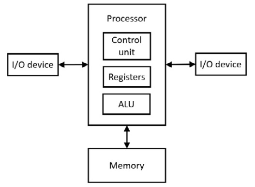
Figure 7.1: The von Neumann architecture
Although the single-memory architectural approach simplified the design and construction of early generations of processors and computers, the use of shared program and data memory has presented some challenges related to system performance and, in recent years, security.
Some of the more significant issues are as follows:
- The von Neumann bottleneck: Using a single interface between the processor and the main memory for instruction and data access often requires multiple memory cycles to retrieve a processor instruction and access the data it requires. In the case of an immediate value stored next to its instruction opcode, there might be little or no bottleneck penalty because, at least in some cases, the immediate value gets loaded along with the opcode in a single memory access. Most programs, however, spend much of their time working with data stored in memory allocated separately from the program instructions. In this situation, multiple memory access operations are required to retrieve the opcode and any required data items.
The use of cache memories for program instructions and data, discussed in detail in Chapter 8, Performance-Enhancing Techniques, can significantly mitigate this limitation. However, when working with code sequences and data objects that exceed the size of cache memory, the benefit of caching is reduced, possibly by a substantial amount. There is no avoiding the fact that placing code and data in the same memory region with a shared communication path to the processor will, at times, act as a limitation on system performance.
- von Neumann security considerations: The use of a single memory area for code and data opens possibilities for creative programmers to store sequences of instructions in memory as “data,” and then direct the processor to execute those instructions. Programs that write code into memory and then execute it are implementing self-modifying code. Besides being difficult to troubleshoot (because many software debugging tools expect the program in memory to contain the instructions that were originally compiled into it), this capability has been exploited for years by hackers with more sinister motives.
Buffer overflow is a distressingly common flaw in widely used software tools such as operating systems, web servers, and databases. Buffer overflow occurs when a program requests input and stores that input in a fixed-length data buffer. If the code is not careful to check the length of the input provided by the user, it is possible for the user to enter an input sequence longer than the available storage space. When this happens, the additional data overwrites memory intended for other purposes.
If the buffer being overwritten is stored on the program’s stack, it is possible for a creative user to provide a lengthy input sequence that overwrites the return address of the currently executing function, which happens to be stored on the same stack.
By carefully crafting the contents of the input data sequence, the attacker can seize control of the executing application and direct it to execute any desired sequence of instructions. To do this, the hacker must prepare an input sequence that overflows the input buffer, overwrites the function’s return address with a different, carefully chosen, address, and writes a sequence of instructions into memory that begins execution at this address. The sequence of instructions inserted by the attacker begins execution when the function that originally requested user input returns, transferring control to the hacker’s code. This allows the hacker to “own” the computer.
Various attempts to resolve the buffer overflow problem have occupied an enormous amount of computer security researchers’ time over the years since the first widespread occurrence of this type of attack in 1988. Processor vendors and operating system developers have implemented a variety of features to combat buffer overflow attacks, with names such as data execution prevention (DEP) and address space layout randomization (ASLR). While these fixes have been effective to some degree, the fundamental processor feature that enables this type of exploitation is the use of the same memory region for program instructions and data in the von Neumann architecture.
The Harvard architecture
The Harvard architecture was originally implemented in the Harvard Mark I computer in 1944. A strict Harvard architecture uses one address space and memory bus for program instructions and a separate address space and memory bus for data. This configuration has the immediate benefit of enabling simultaneous access to instructions and data, thereby implementing a form of parallelism. Of course, this enhancement comes at the expense of essentially duplicating the number of address lines, data lines, and control signals that must be implemented by the processor to access both memory regions.
The following diagram shows the layout of a processor implementing the Harvard architecture:

Figure 7.2: Harvard architecture
The Harvard architecture potentially provides a higher performance level by parallelizing accesses to instructions and data. This architecture also removes the entire class of security issues associated with maliciously executing data as program instructions, provided the instruction memory cannot be modified by program instructions. This assumes the program memory is loaded with instructions in a trustworthy manner.
In hindsight, with knowledge of the proliferation of von Neumann architecture-enabled security threats, there is reason to wonder if the entire information technology industry would not have been vastly better off had there been early agreement to embrace the Harvard architecture and its complete separation of code and data memory regions, despite the costs involved.
In practice, a strict Harvard architecture is rarely used in modern computers. Several variants of the Harvard architecture are commonly employed, collectively called modified Harvard architectures. These architectures are the topic of the next section.
The modified Harvard architecture
Computers designed with a modified Harvard architecture have, in general, some degree of separation between program instructions and data. This reduces the effects of the von Neumann bottleneck and mitigates the security issues we’ve discussed. The separation between instructions and data is rarely absolute, however. While systems with modified Harvard architectures contain separate program instruction and data memory regions, these processors typically support some means of storing data in program memory and, in some cases, storing instructions in data memory.
The following diagram shows a modified Harvard architecture representing many real-world computer systems:

Figure 7.3: Modified Harvard architecture
As we saw in the previous chapter, digital signal processors (DSPs) achieve substantial benefits from the use of a Harvard-like architecture.
By storing one numeric vector in instruction memory and a second vector in data memory, a DSP can execute one multiply-accumulate (MAC) operation per processor clock cycle. In these systems, instruction memory and the data elements it contains are typically read-only memory regions. This is indicated by the unidirectional arrow connecting the instruction memory to the processor in Figure 7.3. Consequently, only constant data values are suitable for storage in the instruction memory region.
Besides DSPs, most modern general-purpose processors contain separate instruction and data caches, thereby implementing significant aspects of the Harvard architecture. Processor architectures such as x86 and ARM support parallel and independent access to instructions and data when the requested items happen to reside in the first level of cache memory. When on-chip cache lookups are unsuccessful, the processor must access the main memory over the von Neumann-style shared bus, which takes significantly longer.
As a practical matter, the implementation details of a particular processor in terms of von Neumann versus Harvard architectural features seldom matter to software developers, other than in terms of performance considerations. Programmers generally develop programs in their high-level language of choice and the compiler or interpreter handles the details related to allocating data and instructions to the appropriate memory regions.
The next section discusses the benefits of memory virtualization.
Physical and virtual memory
Memory devices in computers can be categorized as random-access memory (RAM), which can be read from and written to at will, and read-only memory (ROM), which, as the name indicates, can be read but not written. Some types of memory devices, such as flash memory and electrically erasable programmable read-only memory (EEPROM), inhabit a middle ground, where the data content of the devices can be changed, just not as easily, or as quickly, or updated as many times, as standard RAM.
Memory devices within a computer must be configured to ensure each device occupies a unique span of the system address space, enabling the processor to access each of possibly several RAM and ROM devices by setting the address lines appropriately. Modern computer systems generally perform this address space allocation automatically, based on the slot a memory device occupies.
Software running on early computer systems, and on the less-sophisticated computers and embedded processors of today (such as 6502-based systems), uses addresses within RAM and ROM devices in program instructions to perform reads and writes.
For example, a 6502 instruction such as JMP $1000 instructs the processor to load its instruction pointer with the hexadecimal value $1000 and execute the instruction at that memory location. In processing this instruction, the 6502 control unit places the value $1000 on the 6502’s 16 address lines and reads the byte from that memory address. This byte is interpreted as the opcode of the next instruction to be executed. Similarly, loading a byte from memory with an instruction such as LDA $0200 places the value $0200 on the address lines and copies the byte at that address into the A register.
In systems that use physical addressing, the memory addresses in instructions are the actual addresses of the referenced instruction or data item. This means the memory address contained in an instruction is the same address used to electrically access the appropriate location in a memory device.
This architectural approach is conceptually straightforward to implement in processor designs, but in a scenario involving multiple simultaneously executing programs (referred to as multiprogramming), the burden of software development can quickly become excessive. If each one of multiple programs is developed in isolation from the others (in a scenario involving multiple independent developers, for example), there must be some way to allocate the available RAM and ROM address spaces to individual programs to ensure multiple programs can be in the running state simultaneously (perhaps in the context of an RTOS) without interfering with each other’s use of memory.
One well-known early effort to support the execution of multiple programs in a single address space on PCs is the MS-DOS terminate and stay resident (TSR) program concept. TSR programs allocate memory and load their code into it, and then return control to the operating system. Users can continue to work with the system normally, loading and using other applications (one at a time, of course), but they can also access the TSR as needed, typically by typing a special key combination. It is possible to load multiple TSR programs into memory simultaneously, each accessible via its own key combination. After activating a TSR program, the user interacts with it as needed, then executes a TSR command to return to the currently running main application.
While limited in many ways (including consuming a portion of the maximum of 640 KB of RAM available in early PCs), TSR programs effectively enabled the execution of multiple programs in a single RAM address space.
Developing TSR applications was a challenging task. The more advanced TSR programs available in the 1980s and 1990s took advantage of undocumented MS-DOS features to provide the maximum utility to their users.
As a result of this complexity, TSR programs developed a reputation for causing system instability. A different approach for supporting multiprogramming was clearly needed.
The use of virtual memory overcomes the biggest challenges that prohibited the widespread use of multiprogramming in the original PC design. Virtual memory is a method of memory management that enables each application to operate in its own memory space, seemingly independent of any other applications that may be in the running state simultaneously on the same system. In a computer with virtual memory management, the operating system is responsible for the allocation of physical memory to system processes and to user applications. The memory management hardware and software translate memory requests originating in the application’s virtual memory context to physical memory addresses.
Apart from easing the process of developing and running concurrent applications, virtual memory also enables the allocation of a larger amount of memory than exists in the computer. This is possible using secondary storage (typically a disk file) to temporarily hold copies of sections of memory removed from physical memory to enable a different program (or a different part of the same program) to run in the now-free memory.
In modern general-purpose computers, memory sections are usually allocated and moved in multiples of a fixed-size chunk, called a page. Memory pages are typically 4 KB or larger. Moving memory pages to and from secondary storage in virtual memory systems is called page swapping. The file containing the swapped-out pages is the swap file.
In a virtual memory system, neither application developers nor the code itself need to be concerned with how many other applications are running on the system or how full the physical memory may be getting. As the application allocates memory for data arrays and places calls to library routines (which requires the code for those routines to be loaded into memory), the operating system manages the allocation of physical memory and takes the steps necessary to ensure each application receives memory upon request. Only in the unusual case of completely filling the available physical memory while also filling the swap file to its limit is the system forced to return a failure code in response to a memory allocation request.
Virtual memory provides several notable benefits in addition to making things easier for programmers:
- Not only are applications able to ignore each other’s presence, they are prevented from interfering with each other, accidentally or intentionally. The virtual memory management hardware is responsible for ensuring each application can only access memory pages that have been assigned to it.
Attempts to access another process’s memory, or any other address outside its assigned memory space, result in an access violation exception.
- Each memory page has a collection of attributes that restrict the types of operations supported within it. A page may be marked read-only, causing any attempts to write data to the page to fail. A page may be marked executable, meaning it contains code that can be executed as processor instructions. A page may be marked read-write, indicating the application is free to modify the page at will. By setting these attributes appropriately, operating systems can improve system stability by ensuring processor instructions can’t be modified and that the execution of data as instructions cannot occur, whether such an attempt is the result of an accident or malicious intent.
- Memory pages can be marked with a minimum required privilege level, allowing pages to be restricted for access only by code running with kernel privilege. This restriction ensures the operating system continues operating properly even in the presence of misbehaving applications. This allows system memory to be mapped into each process’s address space while prohibiting application code from interacting directly with that memory. Applications can only access system memory indirectly, via a programming interface consisting of system calls.
- Memory pages can be marked as shareable among applications, meaning a page can be explicitly authorized as accessible from more than one process. This enables efficient interprocess communication.
Early versions of Microsoft Windows implemented some features of memory virtualization using 80286 and 80386 processor memory segmentation capabilities. In the Windows context, the use of virtual memory came into its own with the introduction of Windows NT 3.1 in 1993. The Windows NT system architecture was based on the Digital Equipment Corporation Virtual Address Extension (VAX) architecture, developed in the 1970s. The VAX architecture implemented a 32-bit virtual memory environment with a 4 GB virtual address space available to each of potentially many applications running in a multiprogramming context. One of the key architects of the VAX operating system, Virtual Memory System (VMS), was David Cutler, who later led the development of Microsoft Windows NT.
Windows NT has a flat 32-bit memory organization, meaning any address in the entire 32-bit space is directly accessible using a 32-bit address. No additional programmer effort is required to manipulate segment registers. By default, the Windows NT virtual address space is divided into two equal-sized chunks: a 2 GB user address space in the lower half of the range, and a 2 GB kernel space in the upper half.
The next section delves into the implementation of paged virtual memory in 32-bit Windows NT on Intel processors. While Windows NT is not entirely representative of virtual memory implementations in other operating systems, similar principles apply even though other environments differ in the details. This introduction provides background on the concepts of virtual memory while deferring additional details related to more modern architectures, such as 64-bit processors and operating systems, until later chapters.
Paged virtual memory
In 32-bit Windows NT on Intel processors, memory pages are 4 KB in size. This implies that addressing a location within a particular page requires 12 address bits (because 212=4,096). The remaining 20 bits of a 32-bit virtual address are used in the virtual-to-physical translation process.
In Windows NT, all memory addresses in a program (both those referenced in the source code and in compiled executable code) are virtual addresses. They are not associated with physical addresses until the program runs under the control of the memory management unit.
A contiguous 4 KB section of Windows NT physical memory is called a page frame. The page frame is the smallest unit of memory managed by the Windows virtual memory system. Each page frame starts on a 4 KB boundary, meaning the lower 12 address bits are all zero at the base of any page frame. The system tracks information related to page frames in page tables.
A Windows NT page table is sized to occupy a single 4 KB page. Each 4-byte entry in a page table enables the translation of a 32-bit address from the virtual address space used by program instructions to a physical address required to access a location in RAM or ROM. A 4 KB page table contains 1,024 page address translations. A single page table manages access to 4 MB of address space: each page table contains 1,024 page frames multiplied by 4 KB per page. A process may have several associated page tables, all of which are managed by a page table directory.
A page table directory is a 4 KB page containing a series of 4-byte references to page tables. A page table directory can contain 1,024 page table references. A single page table directory covers the entire 4 GB address space (4 MB per page table multiplied by 1,024 page table references) of 32-bit Windows NT.
Each Windows NT process has a page table directory, set of page tables, and collection of page frames allocated for its use. The process page tables apply to all threads within the process because all the process’s threads share the same address space and memory allocations.
When the system scheduler switches from one process to another, the virtual memory context of the incoming process replaces the context of the outgoing process.
Intel x86 processors maintain the address of the current process page table directory in the CR3 register, also known as the Page Directory Base Register (PDBR). This is the entry point to the page table directory and the page tables, enabling the processor to translate any valid virtual address to the corresponding physical address.
In accessing an arbitrary (valid) location in memory, and assuming information that would expedite the access is not already stored in the cache of recent virtual-to-physical address translations, the processor first looks up the physical address of the relevant page table in the page table directory using the upper 10 bits of the virtual address. It then accesses the page table and uses the next most significant 10 address bits to select the physical page containing the requested data. The lower 12 bits of the address then specify the memory location in the page frame requested by the executing instruction.
Page frames do not represent actual divisions in physical memory.
Physical memory is not actually divided into page frames. The page structure is merely a method the system uses to keep track of the information required to translate virtual addresses to physical memory locations.
To meet users’ performance expectations, each memory access must be as fast as possible. At least one virtual-to-physical translation takes place during the execution of every instruction to fetch instruction opcodes and data. Due to the high-frequency repetition of this process, processor designers expend great effort ensuring virtual address translation takes place as efficiently as possible.
In modern processors, a translation cache retains the results of recent virtual memory translation lookups. This approach enables a very high percentage of virtual memory translations to occur internally in the processor, without any of the clock cycles that would be required if the processor needed to look up a page table address in the page table directory and then access the page table to determine the requested physical address.
The data structures used in virtual-to-physical address translations are not accessible to applications running at user privilege level. All the activity related to address translation takes place in processor hardware and in kernel mode software processes.
To help clarify the operation of virtual address translation, the following diagram presents an example of how Windows translates a 32-bit virtual address to a physical address:
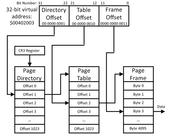
Figure 7.4: Virtual to physical address translation
We’ll go through the translation process in Figure 7.4 step by step. Assume the processor is requesting the 8-bit data value stored at virtual address $00402003 with an instruction such as mov al, [ebx], where ebx has previously been loaded with the value $00402003. We will assume the translation for this address is not already stored in the processor’s cache of recent virtual-to-physical address translations, and we’ll also assume the page is resident in the main memory. The following procedure describes the translation process:
- The processor attempts to execute the
moval,[ebx]instruction, but it cannot complete it because it does not have immediate access to the information needed to perform the translation of the virtual address inebxto the corresponding physical address. This generates a page fault, which transfers control to the operating system so it can resolve the address translation. The use of the term fault here does not imply that an error of some kind occurred. Page faults are a routine part of application execution. - The requested virtual address is shifted right by 22 bit positions, leaving the 10-bit directory offset, which has the value
1in this example. - The directory offset is shifted left by 2 bit positions (because each entry in the page directory is 4 bytes) and is added to the content of processor register CR3 (the PDBR). The result is the address of the page table directory entry containing the address of the relevant page table.
- The requested virtual address is shifted right by 12 bit positions and masked to leave only the 10-bit table offset, which has the value
2in this example. - The table offset is shifted left by 2 bit positions (because each entry in this table is also 4 bytes) and added to the page table address identified in Step 3. The 32-bit address read from this location is the physical address of the page frame containing the requested data.
- The processor stores the translation, which is a conversion from the upper 20 bits of a virtual address to the corresponding upper 20 bits of a page frame address, in its translation cache.
- The processor restarts the
moval,[ebx]instruction, which will now succeed in moving the requested data byte into thealregister using the cached virtual-to-physical translation. The lower 12 bits of the virtual address (the frame offset), which contain the value3in this example, are added to the page frame address computed in Step 5 to access the requested byte.
Once these steps are complete, the translation for the requested page frame remains available in processor translation cache memory for some time. As long as the translation remains in the cache, subsequent requests for the same virtual address or for other locations in the same page frame will execute without delay until the cache entry for this page frame is overwritten by subsequent code execution.
The page fault procedure described in the preceding steps is called a soft fault. A soft fault sets up the virtual-to-physical translation for a page that is already accessible by the processor but is not in the translation cache.
A hard fault occurs when accessing a page that has been swapped to secondary storage. Processing a hard fault requires several additional steps, including allocating a page frame to receive the requested frame, requesting the page from secondary storage, and updating the page table with the physical address of the page. Because hard faults involve a disk transfer, this type of fault has a much greater impact on application performance than a soft fault.
The translation process converts the upper 20 bits of a virtual address to the corresponding 20 bits of the physical address. This leaves 12 bits in each page table entry available to contain status and configuration information for the page frame. The use of these bits is described in the following section.
Page status bits
The following table describes each of the 12 status bits in a 32-bit Windows NT page table entry:
|
Bit |
Name |
Description |
|
0 |
Valid |
1 indicates that this page table entry is usable for translation. If this bit is 0, the remaining bits may have different meanings, as defined by the operating system. The following bit descriptions assume that the valid bit is 1. |
|
1 |
Write |
1 indicates that the page is writeable. 0 means that the page is read-only. |
|
2 |
Owner |
1 indicates that the page is user mode. 0 indicates that the page is kernel mode. |
|
3 |
Write through |
1 indicates that changes to the page are to be flushed to disk immediately. 0 indicates that page changes will be maintained in RAM. |
|
4 |
Cache disabled |
1 indicates that caching is disabled for the page. 0 means that caching is enabled. |
|
5 |
Accessed |
1 indicates that the page has been read or written. 0 indicates the page has not been accessed in any way. |
|
6 |
Dirty |
1 indicates that the page has been written. 0 indicates that no writes have occurred. |
|
7 |
Reserved |
Unused. |
|
8 |
Global |
1 indicates that this translation applies to all processes. 0 means that this entry applies to only one process. |
|
9 |
Reserved |
Unused. |
|
10 |
Reserved |
Unused. |
|
11 |
Reserved |
Unused. |
Table 7.1: Page status bits
The processor uses the page status bits to maintain information about the page content and to control access to each page by system and user processes. The Owner bit identifies a page as owned by the kernel or by a user. User processes cannot read or write any pages owned by the kernel. Any attempt to write to a page marked read-only (where the page’s Write bit is 0) results in an access violation exception.
The system uses the page status bits to manage memory as efficiently as possible. If the Accessed bit is clear, the page has been allocated but never used. When the system needs to free physical memory, pages that have never been accessed are prime candidates for removal because there is no need to save their contents when removing them from memory. Similarly, if a page’s Dirty bit is clear, the page’s data has not been modified since it was brought into memory. The memory manager can release pages that do not have the Dirty bit set with the knowledge that when the page is needed again, it can be reloaded from its source location (typically a disk file) to restore it accurately.
Pages with the Dirty bit set must be stored in the swap file when they are removed from memory. When a page is moved to the swap file, the page table entry is updated using a different format from Table 7.1 to indicate it is not valid for translation (the Valid bit is clear) and to store its location within the swap file.
The format of page table entries is defined by the processor architecture, which, in this case, is the Intel x86 family.
The processor hardware accesses the page table entries to perform virtual-to-physical address translation and to enforce page protections as the processor runs at full speed.
In addition to managing the memory used by each process, the system must keep track of all the RAM and ROM page frames in the computer, whether in use by a process or not. The system maintains this information in lists called memory pools, described next.
Memory pools
Windows NT categorizes memory pools into two types, non-paged and paged:
- Non-paged pool: The non-paged pool contains all page frames that are guaranteed to always remain resident in memory. Code for interrupt service routines, device drivers, and the memory manager itself must always remain immediately accessible by the processor for system performance reasons and, in the case of the memory manager itself, for the system to function at all. Non-paged virtual addresses reside in the system portion of a process’s virtual address space.
- Paged pool: The paged pool contains virtual memory pages that can be temporarily swapped out of physical memory whenever needed.
The system tracks the status of every page frame in physical memory in a structure called the page frame number (PFN) database. The PFN is the upper 20 bits of the physical base address of a page frame. Each page frame can be in one of several states depending on its current and previous usage. These are some of the key page frame states:
- Active: The page frame is part of a system or user process working set. A working set is the portion of a process’s virtual address space currently present in physical memory.
- Standby: Standby pages are pages that have been removed from process working sets and have not been modified.
- Modified: Modified pages have been removed from process working sets and have been modified. These pages must be written to disk before their page frames are reused.
- Free: Free pages are unused but still contain data from their last membership in a working set. For security reasons, these pages cannot be made available to a user process until their data content has been overwritten with zeros.
- Zeroed: Zeroed pages are free and have been overwritten with zeros. These pages are available for allocation by user processes.
- Bad: Bad pages have generated hardware errors during processor accesses. Bad pages are tracked in the PFN database and are not used by the operating system.
As system services and applications start up, run, and shut down, page frames transition between states under system control. In Windows NT, a system task runs during idle periods and converts free pages to zeroed pages by overwriting those pages with zeros.
This discussion has focused on the implementation of virtual memory in the x86 processor architecture under Windows NT. Other processor architectures and operating systems implement virtual memory using similar concepts.
The processor component in control of the memory allocation, address translation, and protection functions is called a memory management unit. The next section examines the memory management unit as a generalized computer system component.
Memory management unit
Processor architectures supporting paged virtual memory either implement the memory management unit (MMU) functionality within the processor itself or, sometimes, particularly in the case of older designs, as a separate integrated circuit. Within the MMU, the processor’s virtual address space is divided into page-sized allocation units.
Pages may be of a fixed size, as in the Windows NT example, or an MMU may support multiple sizes. Modern processors, including later generation x86 processors, often support two page sizes, one small and one large. Small pages are typically a few KB while a large page may be a few MB. Large page support avoids the inefficiencies associated with allocating numerous smaller pages when working with large data objects.
As discussed earlier, the MMU generally contains a cache to improve the speed of memory access by avoiding the need to traverse the page table directory and perform a page table lookup for each memory access. Although the use of caching for performance enhancement is a topic of Chapter 8, Performance-Enhancing Techniques, we introduce the virtual-to-physical address translation cache here because this capability is a core feature of most MMU designs.
The caching component within the MMU that stores previously used virtual-to-physical translations is called a translation lookaside buffer (TLB). To avoid looking up a page table in the page table directory and then looking up the page frame in the referenced page table on every memory access, the TLB stores translations between virtual addresses and page frames resulting from those lookups in a hardware structure called associative memory.
Each time the processor needs to access physical memory, which may occur multiple times during the execution of a single instruction, it first checks the TLB’s associative memory to determine whether the translation information is resident in the TLB. If it is, the instruction immediately uses the information stored in the TLB to access physical memory. If the TLB does not contain the requested translation, a page fault occurs and the processor must traverse the page table directory and a page table to determine the translated address, assuming the referenced page is resident in memory.
The following diagram represents the operation of the TLB:
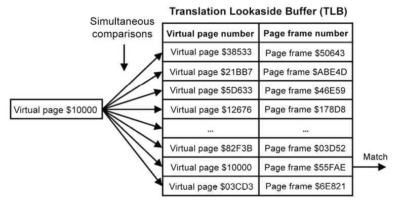
Figure 7.5: Translation lookaside buffer operation
On each memory access, the processor extracts the upper 20 bits of the virtual address to identify the virtual page number. This page number, $10000 in this example, is used to search the TLB for a matching entry. The TLB hardware simultaneously compares the requested virtual page number with all the virtual page numbers resident in the TLB. If a match is found, the corresponding page frame number is immediately provided for use in accessing physical memory.
The TLB contains a limited number of entries, typically 64 or fewer. The processor must manage which TLB entries are retained and which are discarded as address requests for disparate memory locations are processed. When the TLB is full, the MMU decides which of the existing TLB entries to overwrite with new information. The MMU may choose a TLB entry at random for replacement, or a more sophisticated implementation may use age information to replace the TLB entry that has gone the longest without being used.
In addition to performing virtual-to-physical address translation, MMUs generally perform the following functions:
- Separation of virtual memory into kernel space and user space: Kernel memory is reserved for use by the operating system and related components such as device drivers. User space is available for applications and for other actions initiated by users, such as processing commands typed into a command prompt window. User-level code cannot access system memory directly. Instead, user code must call system functions to request services such as the allocation of memory and I/O operations.
- Isolation of process memory: Each process has its own address space, which is the only memory it is allowed to access. Unless a system-authorized memory sharing region is set up between processes, each process is prohibited from accessing memory in use by another process. One process cannot erroneously or intentionally modify memory that is private to another process.
- Page-level access restrictions: In addition to protecting system pages from user access and protecting process-private pages from access by other processes, a process can set protections on individual pages it owns. Pages can be marked read-only, which prohibits the modification of the contents. Pages marked no-execute cannot be used to provide instructions for processor execution. In some architectures, pages can be marked no-access, which prohibits both reading and writing. Pages containing executable code may be marked read-only to prevent the accidental or intentional modification of instructions in memory.
- Detection of software problems: In some programming languages, particularly the C language, it is unfortunately common to attempt to use a pointer (a pointer is a variable that contains the address of another variable) containing an invalid address. The most common invalid address encountered in this situation is 0, because variables are often initialized to zero. This problem is so common that the system’s response to it has its own name: the null pointer exception. When a C program attempts to access a memory location that is not in the program’s valid virtual address range, such as the address
$00000000, the MMU triggers an exception, which, unless handled by the program, typically results in a program crash with an error message printed to the console window. In systems without virtual memory, accesses to erroneous locations may simply read or write the memory at the referenced address without any indication of an error, leading to the incorrect operation of the application or the entire system. Such bugs in systems without an MMU can be extremely difficult to fix if the problem does not become apparent immediately.
Modern processors running Linux, Windows, and most smart-device operating systems generally require their host systems to use virtual memory management and provide the page protection mechanisms described in this chapter.
Real-time embedded processors performing safety-critical tasks such as operating aircraft flight controls or managing automotive airbag operation may or may not support the full feature set of an MMU. One drawback related to the use of virtual memory in hard real-time systems is the variable time delay resulting from the need to process soft faults and, if page swapping is implemented, hard faults. Because execution timing must be strictly controlled in many real-time systems, their designers often avoid the use of virtual memory. Such systems do not contain an MMU, but they often implement many of the other features an MMU provides, such as hardware protection of system memory and access control for RAM regions.
Summary
This chapter examined the principal modern processor architectural categories, including the von Neumann, Harvard, and modified Harvard variants, and their use in different computing domains. The concepts of paged virtual memory were examined, including some details pertaining to the implementation of paged virtual memory in Windows NT on the x86 processor.
The general structure of MMUs was discussed, with emphasis on the use of the TLB as a virtual-to-physical translation performance optimization technique.
The next chapter will expand beyond the performance enhancement provided by the TLB to look in depth at widely used processor acceleration methods including caching, instruction pipelining, and instruction parallelism.
Exercises
- A 16-bit embedded processor has separate memory regions for code and data. Code is stored in flash memory and modifiable data is stored in RAM. Some data values, such as constants and initial values for RAM data items, are stored in the same flash memory region as the program instructions. RAM and ROM reside in the same address space. Which of the processor architectures discussed in this chapter best describes this processor?
- The processor described in Exercise 1 has memory security features that prevent code under execution from modifying program instruction memory. The processor uses physical addresses to access instructions and data. Does this processor contain an MMU?
- The order of accessing sequential elements in a large data structure can have a measurable impact on processing speed due to factors such as the reuse of TLB entries. Accessing distant array elements in sequence (that is, elements that are not in the same page frame as previously accessed elements) requires frequent soft faults as new TLB entries are loaded and old TLB entries are discarded.
Write a program that creates a two-dimensional array of numbers with a large size such as 10,000 rows by 10,000 columns. Iterate through the array in column-major order, assigning each element the sum of the row and column indices. Column-major means the column index (the second index) increments fastest. In other words, the column index increments in the inner loop.
Measure precisely how long this procedure takes. Note, you may need to take steps to ensure your programming language does not optimize away the entire calculation if the results from the array are not used later. It may suffice to print one of the array values after the timing is complete, or you may need to do something like sum all the array elements and print that result.
Repeat the process, including the timing, exactly as explained before, except change the inner loop to iterate over the row index (the first index) and the outer loop to iterate over the column index, making the access sequence row-major.
Since general-purpose computers perform many other tasks while running your code, you may need to perform both procedures multiple times to get a statistically valid result. You might start by running the experiment 10 times and averaging the times for column-major and row-major array access.
Are you able to determine a consistently superior array access method? Which order is fastest on your system using the language you selected? Note that the difference between the column-major and row-major access order may not be dramatic – it might be just a few percent.
Join our community Discord space
Join the book’s Discord workspace for a monthly Ask me Anything session with the author: https://discord.gg/7h8aNRhRuY