
Security Protocols and Their Implementation
In Chapter 1, Data Centers and the Enterprise Network Architecture and its Components, we talked about the network architecture, while in Chapter 2, Network Protocol Structures and Operations, we talked about protocols. In this chapter, we will talk about security protocols, including their pillars, and deep dive into the bits and bytes. This will help us understand how to use these protocols and methods to protect our network resources.
We will start with the basic definitions, continue with the algorithms and higher-level protocols that are used in modern networks, and finish up with network security components, how they work, and how they are used to protect our network resources.
In this chapter, we're going to cover the following main topics:
- Security pillars – confidentiality, integrity, and availability
- Encryption basics and protocols
- Public key infrastructure and certificate authorities
- Authentication basics and protocols
- Authorization and access protocols
- Hash functions and message digests
- IPSec and key management protocols
- SSL/TLS and proxies
- Network security components – RADIUS/TACACS+, FWs, IDS/IPSs, NAC, and WAFs
Security pillars – confidentiality, integrity, and availability
The American National Institute of Standards and Technology (NIST) has defined a framework for cyber security that should be implemented in all aspects of networks and applications. This framework is referred to as the confidentiality, integrity, and availability (CIA) triad. The CIA framework summarizes the requirements for network security, as defined by NIST (https://csrc.nist.gov/glossary/term/availability), as follows:
- Confidentiality: Preserving authorized restrictions on information access and disclosure, including means for protecting personal privacy and proprietary information.
- Integrity: Guarding against improper information modification or destruction. This includes ensuring information non-repudiation and authenticity.
- Availability: Guarding against improper information modification or destruction. This includes ensuring information non-repudiation and authenticity.
The following protocols and mechanisms provide these requirements.
Encryption basics and protocols
Encryption is the process of converting information that can be read by everyone – that is, cleartext or plaintext – into secret information called ciphertext that can only be accessed by authorized users.
Encryption requires an algorithm and a key. The algorithm is a mathematical procedure made up of a series of calculations, while the key is a string of bits. The smarter the algorithm is and the longer the key is, the more difficult it will be to break it.
Services provided by encryption
Encryption is a service that hides the content of the data. Encryption does not authenticate the source of the data, it does not hide the source and destination of the data, and it does not check the integrity of the data. For these purposes, we have other mechanisms that we talk about later in this chapter:
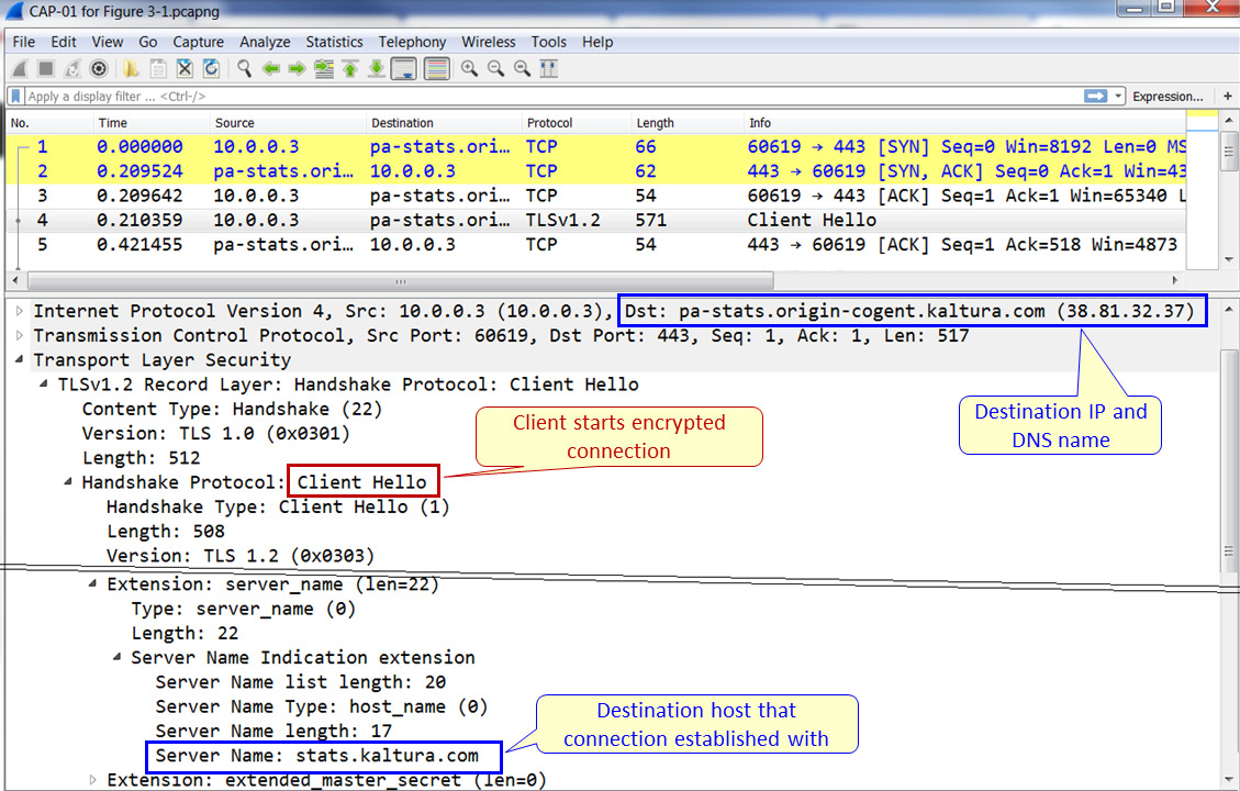
Figure 3.1 – Sending information during encryption
An example of the information that is seen and hidden can be seen in the preceding screenshot. Here, we can see the IP address of the destination, as well as the server name in the Transport Layer Security (TLS) header. In a message sent later in the session, as we will see later in this chapter in the asymmetric protocols section, we will see the cipher suite that is used for the session.
Stream versus block ciphers
There are two ways to encrypt data in transport. As shown in the following diagram, these are stream ciphers and block ciphers:
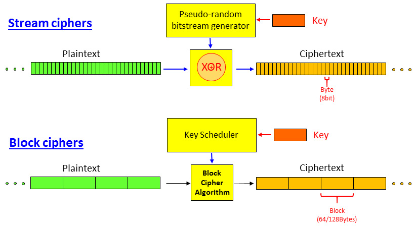
Figure 3.2 – Stream versus block ciphers
- In a stream cipher, as shown at the top of the preceding diagram, the data stream is encrypted byte by byte. A key is used to generate a pseudorandom bitstream that is XOR'd with the plaintext entering the cipher. The result is an encrypted byte stream.
- In a block cipher, the data is split into blocks of 64 bits or more. A key is used with a key scheduler to encrypt each block independently.
Symmetric versus asymmetric encryption
Encryption is performed by using a key and an algorithm. There are two types of encryption:
- A secret key or symmetric encryption uses the same key to encrypt and decrypt the information. Here, we have protocols such as Data Encryption Standard (DES), Triple-DES, and Advanced Encryption Standard (AES).
- A private key or asymmetric encryption uses two keys – the first key to encrypt the data and a second key to decrypt the data. Here, we have protocols such as Pretty Good Privacy (PGP) and Rivest–Shamir–Adleman (RSA).
Encryption can be implemented on data at rest, which is data that is stored somewhere on a PC, smartphone, central server, and so on. Encryption can also be implemented on data in transit, which is information that's moving through a network from one place to another. In this book, we will focus on network security, so we will mostly talk about data in transit.
Symmetric encryption protocols
The first type of protocol we will look at is the symmetric encryption protocol, in which both sides of the connection use the same key. The key can be permanent or can be replaced every second but still, both sides share the same key. As shown in the following screenshot, the plaintext is encrypted with encryption function fE with the K' key, and then opened with fD when functions fE and fD are equal and so are the K' keys:
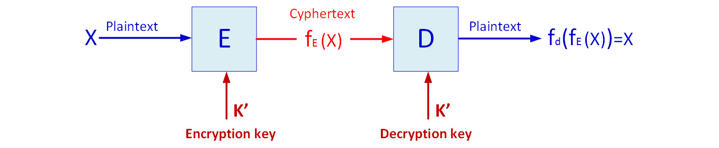
Figure 3.3 – Symmetric encryption
Many symmetric protocols have been developed over the years. There are many types of symmetric protocols, including RC5 and RC6. The most common algorithms that were used in the past and are still used today in data networks are DES, Triple-DES, which was common some years ago, and AES, which is the most secure and popular in the last few years. Let's take a brief look at each. They will be explained in general terms, with the minimum amount of knowledge that is required to understand the mechanisms.
Data Encryption Standard (DES) and Triple-DES (3DES)
Data Encryption Standard (DES), which was standardized in 1979, is a block cipher that tales fixed-length strings of plaintext bits and, using the key and the algorithm, transforms each into another ciphertext bitstream of the same length. The algorithm is based on 16 rounds of encryption, with block sizes of 64 bits and key sizes of 56 bits.
The algorithm, called the Feistel algorithm, is based on the principle shown in the following diagram:
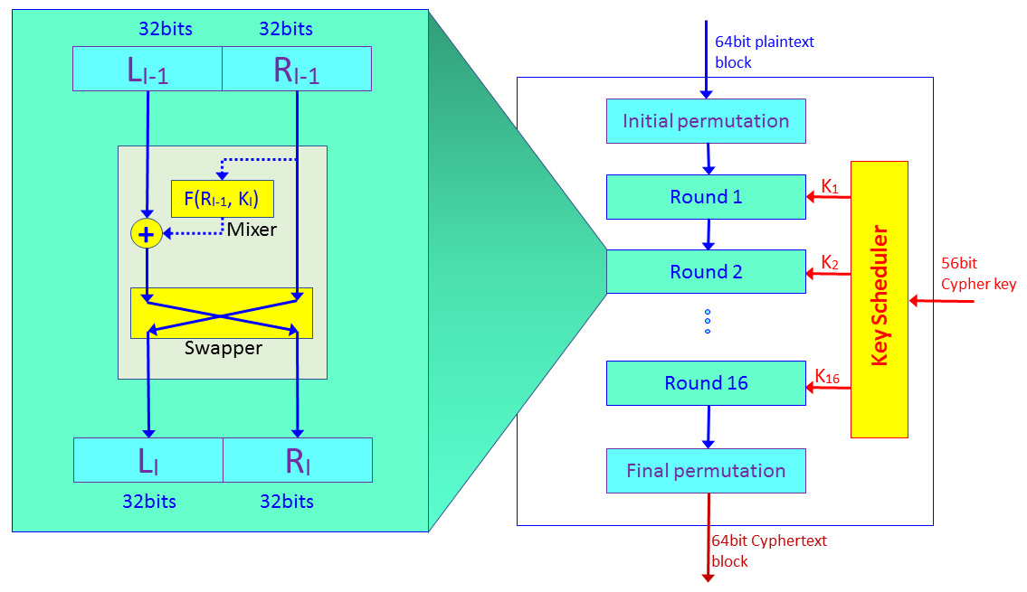
Figure 3.4 – DES algorithm
The algorithm works as follows:
- Before entering the encryption, each plaintext block of 64 bits goes through the initial permutation of the 64 bits. This is done by changing the bits' locations; for example, the first bit in the block is replaced with the 48th bit, the second bit is exchanged with the 35th bit, and so on.
- The 64-bit block is divided into two halves of 32 bits each.
- Encryption is done in 16 rounds. In each round, as shown on the left of Figure 3.3, we split the 64-bit block into two halves. One half is encrypted and XOR'd with the second half, which is not. Then, the two parts are swapped and we move on to the next step.
- The next set of keys are generated at the key scheduler when keys K1 to K16 are generated from the original 56-bit key. Keys are generated by bit-shifting the original key.
As a protocol developed in the 1970s, DES is an easy-to-break encryption mechanism and is hardly used in recent years.
Triple-DES or 3DES is an algorithm that was developed in the mid-1990s and published as RFC 1851 by the IETF. 3DES uses the same algorithm a DES but with three keys. Keys can be independent when K1 = K2 = K3 (keying option1), K2 and K1 = K3 (keying option 2), and identical keys K1 = K2 = K3 (keying option 3).
Although 3DES works with 112- or 168-bit keys (56*2 or 56*3 bits, depending on the keying option), using DES is also easy to break. Due to this, a new algorithm was accepted: AES.
Advanced Encryption Standard (AES)
The National Institute of Standards and Technology (NIST) selected the Rijndael algorithm (designed by Joan Daemen and Vincent Rijmen) as the successor of DES and 3DES in November 2001. AES has a fixed block size of 128 bits, with key sizes of 128, 192, and 256 bits, and uses an algorithm that is far more complex than the DES/3DES Feistal algorithm:
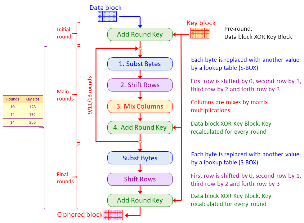
Figure 3.5 – The AES algorithm
As we can see, the algorithm in AES works as follows:
- A data block enters the algorithm and is XOR'd with the initial key block.
- After the initial round, the block enters the rounds of substitution – rows shift, column mixture, and XOR. This main round takes place 9, 11, or 13 times, depending on the key's length.
- In the final round, the block enters a single round of substitution – rows shift and XOR – and exits the algorithm as a strongly encrypted block.
- The key is changed for every round based on the manipulation from the previous round key.
At the time of writing this book, there is no known successful attempt at hacking the algorithm by any commercial or academic organization.
Asymmetric encryption protocols
In asymmetric protocols, we use two keys: one key is used to encrypt the data while another key is used to decrypt it. The key that is used to encrypt the data is called the public key, while the key that is used to decrypt the data is called the private key. This is also known as public key cryptography.
As shown in the preceding diagram, public key cryptography is used in two ways:
- For encrypting information between users
- For signing documents with digital signatures
Data encryption
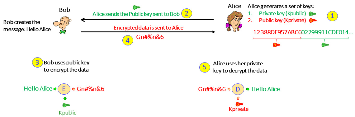
Figure 3.6 – Data encryption in asymmetric cryptography
Let's look at this in more detail:
- First, Alice generates a key pair. This is a string of bits where half of it is the public key and the other half is the private key.
- Once the keys have been generated, Alice sends the public key to Bob.
- Bob generates the message and encrypts it with the public key.
- Bob sends the encrypted message to Alice.
- Alice, who has the secret key, decrypts the message.
Alice can give the public key to everyone that wishes to communicate with her so that everyone can send her encrypted messages, but only she can open them with her private key.
Digital signatures
Digital signatures are used so that a user can sign a document and send it to someone else and the receiver can be sure it was sent by the claimed originator and not by someone else. Creating and using digital signatures is the opposite of data encryption.
In our example, Alice wants to send a verified document to Bob:
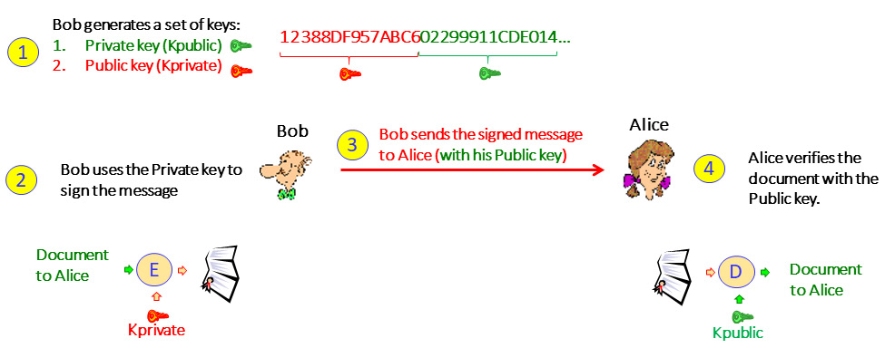
Figure 3.7 – Digital signatures
With digital signatures, we do the following:
- First, like in encryption, Bob generates a key pair. This is a string of bits where half of it is the public key and the second half is the private key.
- Bob sends the public key to Alice.
- Bob uses the private key to sign the document.
- Bob sends the message to Alice.
- Alice receives the message and can verify that the public key can decrypt the message, which proves that Alice's secret key was used to encrypt it.
Important Note
In practice, both in data encryption and in digital signatures, a hash is generated before the data is encrypted and checked when data is received. We skipped this step to make the explanation clearer. Hash and hashing algorithms will be explained later in this chapter.
Asymmetric encryption protocols and RSA
Several asymmetric algorithms are used: Rivest-Shamir-Adleman (RSA), El Elliptic Curve Cryptography (ECC), El Gamal, Digital Signature Algorithm (DSA), and others. In this section, we will talk about the RSA algorithm, which is by far the most widely used commercial algorithm.
The RSA algorithm is based on the mathematical principle that it is easy to multiply large numbers but splitting them into their factors is much harder. This is especially true when we multiply two prime numbers; to multiply them is easy but to get their factors from the result is virtually impossible and requires enormous computing power.
The algorithm works as follows (shown by using an example):
- The user, User A, creates the keys and chooses two prime numbers, p and q. Their product, n=pq, will be half of the public key.
- User A calculates the function of p and q, which is ɸ(p,q), when ɸ(p,q) = (p-1)(q-1).
Let's assume ɸ(p,q) = (11-1)(17-1) = 10*16=160.
- User A chooses a number, e, that is relatively prime to p and q.
Numbers are relatively prime if there is no integer greater than one that divides them both.
We will choose e=3, which is relatively prime to 11 and relatively prime to 17.
- The public key's first half is n=pq, while and the second half is e.
The public key is 187,3.
- User A calculates the modular inverse, d, of e modulo ɸ(n).
Inverse of the integer, x, is a number, y, so that xy=1.
Modulo finds the remainder after dividing one number by another. The remainder is called the modulus of the operation.
A modular inverse of an integer a is an integer, x, where the product, ax, is congruent to 1 concerning modulus m, which is ax ≡ 1 (mod m).
ɸ(n)=160 and therefore d = 3 modulo 160 = 107
- User A distributes the public key n,e, and keeps secret the private key, d.
Now that we've learned about the bits and bytes, let's look at the bigger picture and talk about certificates.
Public key infrastructure and certificate authorities
Public key infrastructure (PKI) defines the architecture for secured communications between users. PKI defines a certificate authority (CA) that contains several attributes to be used between users that establish communications.
PKI provides several services:
- Authentication: To prove to each side that the other side is who it claims to be
- Integrity: To prove that data has not been changed during transmission
- Confidentiality: To prove that no one can read the data during transmission
PKI standardized the process of using certificates and using private and public keys for secure communications between entities.
PKI is mostly used to connect to web servers using Secure Socket Layer/Transport Layer Security (SSL/TLS). In this section, we will describe the process and, in the SSL/TLS and Proxies section, later in this chapter, we will get to the bits and bytes.
First, let's see how a client connects to a web server using certificates. This is illustrated in the following diagram:
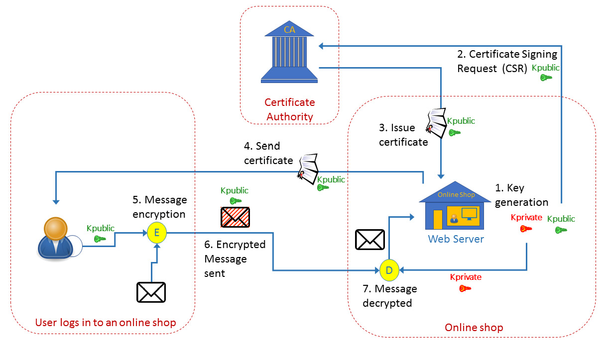
Figure 3.8 – How certificates work
Let's consider an online store that wishes to sell items on the internet. We can see this to the right of the preceding diagram. Here, the following will happen:
- The online store's website generates two keys: the private key and the public key.
Important Note
For internal organization work, Step 1 is the only thing you need. You generate the key, distribute it to communication parties, and start sending information. When you implement a website, you need to trust your communication's party, and your communication's party needs to trust you, so a mutual entity is required that can establish this trust. The mutual entity that both of you trust is the CA.
- When the key is ready, the store sends a Certificate Signing Request (CSR) to the CA. A CSR is an encoded file that is sent to a CA such as https://www.verisign.com/, https://www.digicert.com/, www.cloudflare.com, or others, that includes your public key and identity information. The CA verifies the identity of the requester by asking for information such as the URL (www.example.com), the organization's name, and the address to verify the requester's identity.
- After confirmation, the CA sends the certificate to the web server owner. The certificate includes the public key, along with the certificate and CA's identification.
- Now, when a customer, which is shown as the little man on the left in the preceding diagram, connects to your website, they open the website and see the little padlock on the web page. If you click on it, you will see the certificate details; that is, the issuer, the public key, the validity dates, and more.
- The customer encrypts the information with the public key.
- The customer sends the encrypted information to the web server.
- The web server uses the private key to decrypt the information.
In digital signatures, we use the same mechanism but the opposite way. We send our private key to everyone that wishes to send us documents, and we use the public key to open it.
Authentication basics and protocols
Authentication is a process that identifies a person, device, or software process that's accessing data or information. Authorization is a process that grants access rights to perform actions on data or information.
There are three types of authentication mechanisms. These are what you know, what you have, and what you are:
- What you know: Usually user and password authentication
- What you have: Usually smart cards and card readers
- What you are: Biometrics such as fingerprint or eye retina scanning
There are several resources that we usually access:
- The organization networks. This is usually done with an SSL/TLS-VPN or IPSec VPN, which we will talk about later in this chapter.
- External web services (bank accounts, social networks, and so on). This is usually done with HTTPS, which uses SSL/TLS.
- Internal access to organization resources. This is provided by Microsoft or Linux mechanisms, and RADIUS/TACACS+ to access communication equipment.
There are several levels of authentication; we will look at each in this section, along with their vulnerabilities.
Authentication types
In this section, we will talk about authentication types, from the basic to the advanced methods.
Username/password and challenge authentication
The most basic type of authentication is a username and password. This method is subjected to several types of attacks. The Password Authentication Protocol (PAP) is an example of a protocol that implements this method, where the initiating device sends an authentication request with a username and password, and the authenticator (the responding device) looks at it and sends an authentication-acknowledge or authentication-not-acknowledge message.
Another protocol in this category is the Challenge Handshake Authentication Protocol (CHAP), which uses a three-way handshake. Here, after the link establishment phase is complete, the authenticator (that is, the peer that allows or blocks the access) sends a challenge message to the initiator. The initiator responds with a string that contains a value that's calculated using a hash function. The authenticator checks if this response is equal to its calculation of the string. If the values match, the authentication is acknowledged; otherwise, it is not.
These two protocols were first standardized in RFC1334 (IETF, October 1992) for the Layer 2 Point-To-Point Protocol (PPP), which was mainly used to establish connectivity between routers.
The level of security in these protocols is very low. PAP is subjected to user/password cracking, while CHAP is subjected to simple man-in-the-middle attacks. These protocols were used mostly over point-to-point router connectivity and are hardly used anymore.
Username/password with IP address identification authentication
Username and password authentication can be taken one step forward by using a username and password along with restrictions on the source IP address that the request to log in can come from. Although this method has a slightly higher security level, you should be careful about using it.
In this case, when configuring this restriction inside your organization, such as when the network administrator can only access communication equipment from their PC with a username and password, it's not the best way but it provides moderate level of security.
Configuring your firewall to allow access from the internet based on a username/password and IP address is like putting your hand in a fire, hoping it will come out cold. If someone wants to break in, IP address spoofing with username/password cracking will easily do the job. IP spoofing attacks will be explained in more detail later in this book.
Encrypted username/password authentication
This is the most common way of accessing organizations or public servers (banks, social networks, and so on) and is one step lower than one-time passwords (OTPs) and biometrics.
Here, we use protocols such as IPSec for client to site connectivity, which is when your computer becomes a client of your organization, or SSL/TLS connectivity, which is when the connection is per application – for example, HTTPS for accessing a web server, secure FTP for accessing an FTP server, SIPS for secure access to Session Initiation Protocol (SIP) servers, and so on.
The next level of security is using OTPs. There are two versions of OTP that are based on the same principle:
- A software or hardware device that generates a one-time code that you use to log into your organization. This method is called HMAC-based OTP (HOTP).
- A code that is generated and sent to you when you access a bank account, credit company, healthcare organization, and so on. This method is called SMS-based OTP (TOTP).
HMAC-based OTP (HOTP)
The first method, known as HOTP, was first standardized in RFC4226 (IETF, December 2005). This method uses tokens that are synchronized with the server to provide the user with a one-time password to allow access to the network. The password can only be used once, so it eliminates the possibility of reply attacks. HOTP is calculated as follows:
HOTP(key,counter)=Truncate(HMAC-SHA-1(key,counter))
The parameters in this formula are as follows:
- Key: The HMAC key, also called the seed, is a shared secret key that's agreed up by the server and the client at the time of initialization. The key is static for the lifetime of the client. For security purposes, it must be kept secret by the client and the server.
- Counter: This is incremented by one after each successful authentication, so it should be in sync between the client and the server.
- HMAC-SHA-1: This is the derivation algorithm used by the HOTP method.
The truncate function is used to truncate the 160 bits of HMAC-SHA-1 into a user-readable format of several digits.
There are some issues with HOTP. The protocol is counting the number of successful authentication attempts, so what happens in the case of unsuccessful attempts? These issues are addressed by the standard and solutions are proposed for each.
Time-based one-time password (TOTP)
The second method is known as time-based one-time password (TOTP), which was first standardized in RFC6238 (IETF, May 2011) as an extension of HOTM. It uses the same HOTP algorithm for calculating the OTP, but instead of using a counter, it uses a timer. So, TOTP is calculated as follows:
TOTP(key,time)=Truncate(HMAC(key,time))
In TOTP, the hash algorithm may be HMAC-SHA-1, HMAC-SHA-256, or HMAC-SHA-512. The time is counted in 30-second increments due to the epoch time (number of seconds that have elapsed since midnight UTC (coordinated universal time) of January 1, 1970).
TOTP eliminates the counter issues that were in HOTP, but there are also several issues with it. With TOTP hardware tokens (not like software tokens, which use the smartphone clock), we need clocking capabilities, which require an internal accurate oscillator, time-drifts can happen, and so on. These issues are addressed by the standard and solutions are proposed for each.
SMS-based OTP
This method is straightforward. Here, the user logs into the website with their username and password. When the username and password match, the user receives an OTP via SMS or email. The user enters this OTP and logs into the website. Instead of a username and password, it can be a user ID or passport number, the last digits of the credit card owned by the user, and so on. This is a two-factor authentication method that uses a combination of what you know and what you have.
Extensible authentication protocol (EAP)
The extensible authentication protocol (EAP) is a standard that provides a framework that contains a set of things that are required for clients to authenticate with network authentication servers, such as a laptop connected to a Wi-Fi network. The EAP framework constitutes the method and the requirements, while the authentication protocol can be selected by the clients performing the authentication mechanism dynamically.
EAP was first introduced in RFC2284 (IETF, March 1998) for the point-to-point protocol to add security over the existing (at this time) PAP and CHAP. Later, it was enhanced in RFC3748 (IETF, June 2004). Since then, it has been implemented in other areas, mostly in wireless and wireless LANs using the IEEE 802.11i and 802.1x protocols.
EAP protocols
Several EAP-based methods have been standardized by the IETF:
- EAP-TLS: Based on TLS authentication with certificate-based mutual authentication and key derivation. Defined in RFC5216 (IETF, March 2008).
- EAP-SIM: Defined for authentication and key derivation using the GSM SIM card. Defined in RFC4186 (IETF, January 2006).
- EAP-AKA: Defined for authentication and key derivation using the UMTS SIM card, based on the UMTS AKA standard. First defined in RFC4187 (IETF, January 2006).
- EAP-AKA′: Provides an improved key separation between keys generated for accessing different access networks. First defined in RFC5448 (IETF, May 2009).
Due to its flexibility, EAP was adopted in later standards such as for Wi-Fi integration with LTE (RFC7458, IETF, February 2015), EAP-TTLS, which lets you tunnel other authentication protocols over EAP tunnels (RFC5281, IETF, August 2008), and in proprietary implementations and other standard and proprietary implementations such as Lightweight EAP (LEAP) and Flexible Authentication via Secure Tunneling EAP (EAP-FAST) from Cisco, Protected EAP (PEAP) from Microsoft, EAP over LAN (EAPoL), which is used in port-based network access control in LANs (IEEE, 802.1X), and others.
EAP-AKA and EAP-SIM use challenge-response authentication (such as CHAP), while EAP-TLS, EAP-TTLS, PEAP, and EAP-FAST use TLS authentication.
EAP architecture
The EAP architecture is based on three entities:
- The EAP Peer: This is the entity that requests access to the network. This is usually a PC, laptop, tablet, and so on. In 802.1X, it is referred to as the supplicant.
- The EAP Authenticator: The entity that the peer connects to, such as the wireless LAN access point, LAN switch, cellular network gateway (LTE ePDG), and so on.
- The EAP Server: The authentication server that provides authentication services to the authenticator, such as a Remote Authentication Dial-In User Service (RADIUS) server.
The EAP procedure is illustrated in the following diagram:
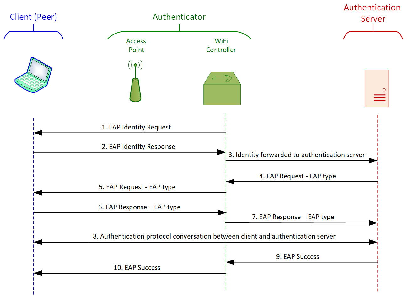
Figure 3.9 – EAP authentication procedure example
This example is from a Wi-Fi network. A client (called a peer in the EAP protocol) connects to the network. The Wi-Fi controller (which, together with the access point, establishes the EAP authenticator) senses a new client and sends an EAP identity request (1). The client answers with an EAP identity response (2), and the controller forwards the response to the authentication server (3). The authentication server sends an EAP type request to the authenticator (4), who forwards it to the client (5). The EAP type request is a request from the server, telling it the server's authentication type. If the client supports it, it answers with an EAP type response, confirming the authentication type (6), and the authenticator forwards it to the server (7). At this stage, the client and the server negotiate according to the requested authentication method (TLS, TTLS, and so on) (8), and if the negotiation succeeds, the server sends an EAP success message to the authenticator (9), which forwards it to the client (10). At this point, the client is logged in and connected to the network.
Authorization and access protocols
As we saw in the previous section, authentication is responsible for validating a user's identity, confirming who they are and if it is really who they say they are. Authorization combines identity information with access information to allow the user to read, write, execute, or delete files and information based on their identity and privileges.
Network access control (NAC) devices are used to enforce the cooperate policies. NAC functions and capabilities will be discussed in the last section of this chapter, RADIUS, NAC, and other authentication features.
Hash functions and message digests
Message authentication is used for the following purposes:
- Protecting message integrity: To verify that a message that is sent is not changed during transmission.
- Verifying message authenticity: To validate the identity of the message originator; that is, to verify who we get the message from.
- Non-repudiation of its origin: To assure the sender that the message was delivered, and to assure the recipient that it is from the sender. This ensures that neither of them can deny that the message was processed.
A hash function is a mathematical function that accepts a variable-length block of data as input and produces a fixed-size hash value as output. The hash function's calculation result is called a message authentication code (MAC).
Hash functions are used to check data integrity. Some applications of hashes are as follows:
- In security: To check if the messages or files that have arrived are the same ones that were sent.
- In data communications: To check the integrity of arriving frames, such as Ethernet checksums.
- In intrusion detection: To check if the messages were changed during transport to bypass protection mechanisms.
- Virus detection: To detect files that were changed by a virus.
Two parameters should be supported by a hash function:
- One-way hash: It should be computationally infeasible to resolve the origin data from the hash.
- Collision-free hash: It should be infeasible to find two messages with the same hash.
A simple hashing mechanism is only used for message integrity checks, as shown in the following diagram:
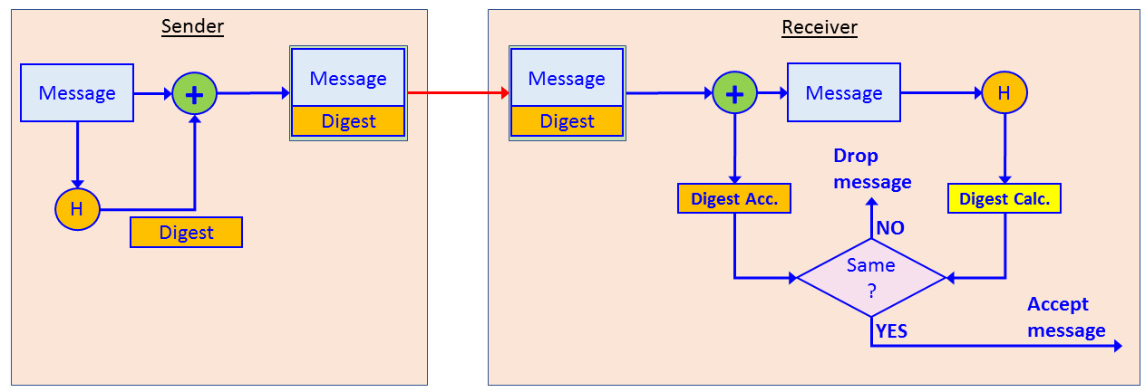
Figure 3.10 – Simple hash operation
Here, we can see that the sender uses a hash function to add a message digest to the message. The message is sent to the receiver, who splits the digest from the original message and calculates it again. If the digest value that is received is equal to the value that is calculated, the message is accepted. If they are different, the message is dropped.
When the hash is used with encryption, as shown in the following diagram, when encryption is used, it is the same mechanism as encryption/decryption:
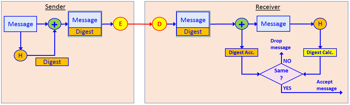
Figure 3.11 – Hash functions with encryption
Encryption can be symmetric or asymmetric, and when asymmetric, it can be used for encrypting the public key to access a secure web page or encrypting the private key to sign a document.
The most common hash functions are Message Digest 5 (MD5) and Secure Hash Algorithm 1 (SHA1). MD5 was first standardized in RFC1321 (IETF, April 1992). MD5 generated a digest of 128 bits. SHA1 was first standardized by the US National Institute of Standards and Technology (NIST) and creates 160-bit digests. Although smarter and safer hash algorithms have been developed since MD5 and SHA1, such as SHA2, SHA3, and others, MD5 and SHA1 are still the most common hash standards in commercial implementations.
IPSec and key management protocols
IPSec is a set of protocols designed to provide Virtual Private Network (VPN) functionality. We will talk about VPNs types and connectivity first before learning about the protocol. IPSec was first standardized in RFC 2401 (IETF, November 1998) and later became obsolete with RFC 4301 (ISTF, December 2005) and has been updated by other RFCs.
IPSec provides the following services:
- Confidentiality: By encrypting data between the sender and the receiver
- Integrity: By adding a hash function to the data
- Authentication: By providing authentication between the two ends
- Anti-Replay: By sequencing packets that are sent between the two ends
VPNs
A VPN is a way to establish a virtual connection over public infrastructure. Establishing a virtual connection is usually achieved by tunneling, which is a very common mechanism in data communications that encapsulates an internal packet into an external header that will carry it through the public network. The following diagram shows an example of encapsulating a simple tunnel:
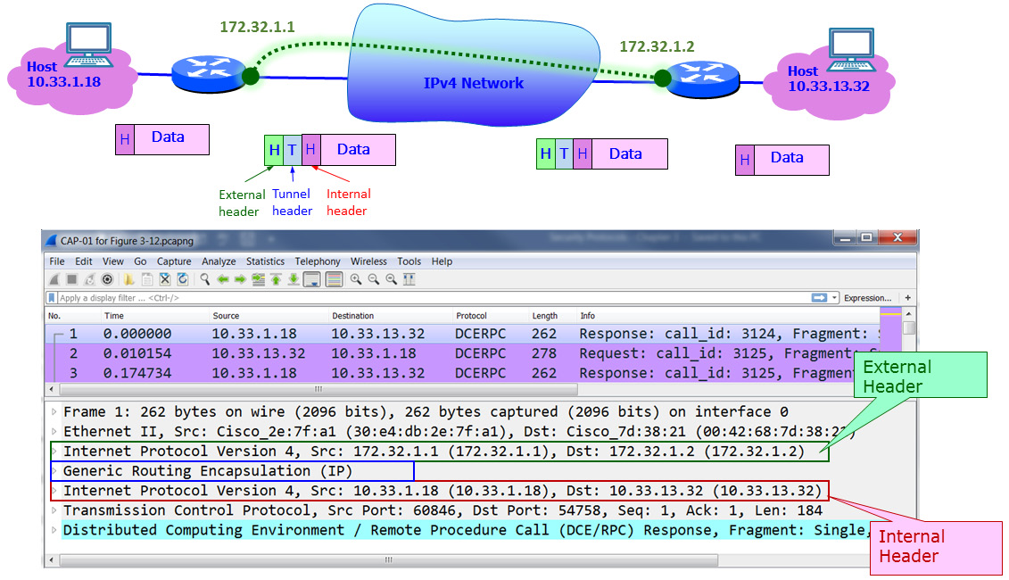
Figure 3.12 – Tunneling
Here, we can see two routers connected to the internet. On the left, we have host 10.33.1.18, while on the right, we have host 10.33.13.32. We create a tunnel between the two routers, and the tunnel addresses are 172.32.1.1 for the left router and 172.32.1.2 for the right router.
As shown at the bottom of the diagram, which is of a Wireshark capture file, an external header is the first thing that appears. Right after the Ethernet header, it carries a tunnel header – in this example, a Generic Routing Encapsulation (GRE) tunnel header – and then comes the internal IP header with the tunnel addresses.
When we forward traffic over the internet, we need firewalls that connect to the internet on both sides, we need an authentication protocol so that the firewalls can authenticate each other, and we need to encrypt the information that runs through the internet between the firewalls. This is shown in the following diagram:
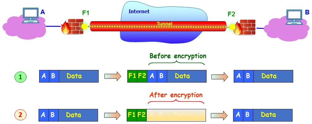
Figure 3.13 – Encrypted tunnel between firewalls
Un the top packet example (1), we can see the traffic when it's not encrypted, with external IP addresses of F1 and F2. These are the external addresses of the firewalls. The internal addresses are those of the PCs on both sides; that is, A and B.
In the bottom packet example (2), we can see that the internal header and data are hidden, as they should be when transferred over the internet, and that the only thing an eavesdropper will see is the addresses of the firewalls. The purpose of IPSec is to create this tunnel.
IPSec principles of operation
As shown in the following diagram, there are three ways to use IPSec:
- Site to Site (1) is when we connect a firewall to a firewall so that the two locations are connected as they have a direct line between them. This type of connectivity is transparent to the user, who works on remote servers as they are part of the network.
- Client to Site (2) is when you connect to your work with a VPN client. You run the client, enter a username and password, and, if required, a code from your token and log into the network.
- Client to Client (3) is when two clients connect and encrypt the information between them. This option should be more frequent in IPv6 since IPSec is an inherent part of the protocol and every device contains the client's internet address:
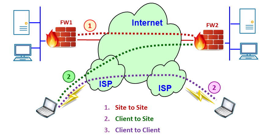
Figure 3.14 – IPSec modes of operation
In the next section, we will describe the protocol and how tunnels are initialized and maintained during operation.
IPSec has three steps of operation:
- IKE Phase 1: Negotiating the security parameters and building the IKE phase 1 tunnel.
- IKE phase 2: Building the IKE phase 2 tunnel.
- Data Transfer: Sending the information over the tunnel that was created in IKE phase 2.
In the next section, we will look at these three steps in more detail.
IPSec tunnel establishment
Before moving traffic over IPSec, the two peers establish a secure channel. This is provided by a protocol called Internet Key Exchange (IKE), also known as Internet Security Association and Key Management Protocol (ISAKMP).
Important Note
ISAKMP was a protocol that was standardized in RFC 2408 (IETF, November 1998) that established secure communications between two peers over the internet. RFC 2409 (IETF, November 1998) was published at the same time and described the usage of Oakley (a key management protocol), SKEME, and ISAKMP for the same purpose. IKEv2 was first standardized in RFC 4306 (IETF, December 2005) and combined these two RFCs (along with RFC2407 for DOI) and obsoleted them. In Cisco, they refer to IKE and ISAKMP as the same protocol, and in Wireshark, you see ISAKMP and not IKE, so practically, IKE and ISAKMP can be considered the same. The latest standard for IKEv2 is RFC 7296 (IETF, October 2014), with updates in RFCs 7427, 7670, and 8247.
The IKE protocol is used to establish the IPSec tunnel between two peers and works in three stages.
The first stage is negotiation. This step is initiated by the peer that wanted to send data to the other. In this step, the following parameters are negotiated:
- Hashing algorithm: Several options can be used. The common ones are MD5 and SHA.
- Authentication: The two peers identify each other. Pre-shared keys and digital certificates are the most common ones.
- Diffie-Hellman (DH) Group: The strength of the key that will be used in the key-exchange process (groups defined in RFC 3526).
- Lifetime: How long IKE phase 1 will take. The quicker it takes, the more secure it is.
- Encryption: What algorithm will be used for encryption.
The second step is the key exchange. After the negotiation stage, the two peers will exchange keys. By the end of this stage, the two peers will have a shared key.
The third stage is authentication. In this stage, the two peers authenticate each other using the authentication method they decided on in stage 1.
IPSec modes of operation
IPSec has two modes of operation: tunnel mode and transport mode:
- IPSec Tunnel Mode: The entire IP packet is encrypted and hidden inside the new IP packet. In tunnel mode, the original IP packet is encrypted and encapsulated inside a new IP external header. This is an implementation of what we saw in Figure 3.12. Tunnel mode is mostly used between firewalls in a site-to-site topology or between the client and firewall in a client-to-site topology.
- IPSec transport mode: The IPSec header is added to the original IP packet. It is commonly used in client-to-site VPNs. Transport mode is used to protect layers 4 to 7. This method is usually used between the client and server or between end nodes, which can be behind firewalls.
IPSec authentication and encryption protocols
The protocols involved in authentication and integrity are AH and ESP:
- Authentication Header (AH): This provides integrity and anti-replay protection. AH protects the IP packet by generating a hash function and providing a hash value.
- Encapsulating Security Payload (ESP): This provides integrity, anti-replay, and encryption protection, which is why it is the most popular option.
IPSec AH protocol
The following diagram shows the packet structure of the AH transport mode and AH tunnel mode. In these modes of operation, IPSec only implements authentication to calculate a hash function over the entire packet:
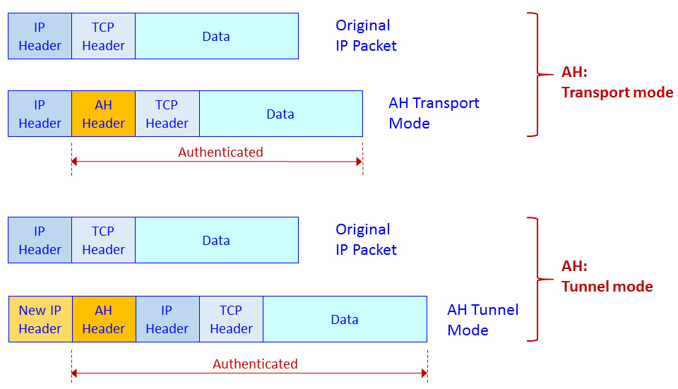
Figure 3.15 – IPSec AH transport mode and tunnel mode – packet structure
The AH header includes the following fields: Next header, to point to the upper layer protocol (for example, TCP or UDP); Length, to indicate the length of the AH header; Security Parameters Index (SPI), to identify the flow that the packet belongs to, Sequence, which is a sequence number to protect against replay attacks; and Integrity Check Value (ICV), which is the hash value.
IPSec ESP protocol
The following diagram shows the packet structure in ESP transport mode and ESP tunnel mode. In these modes of operation, IPSec implements authentication and encryption to calculate a hash function over the entire packet and encrypt the packet:
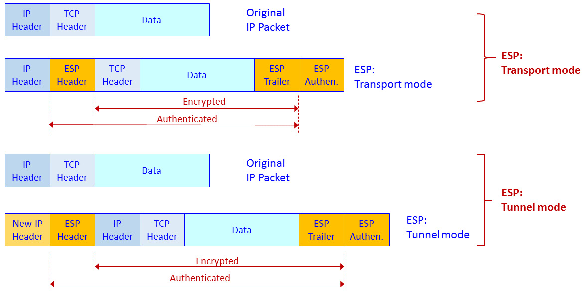
Figure 3.16 – IPSec ESP transport mode and tunnel mode – packet structure
In ESP transport mode, we add an ESP header and trailer. Encryption is provided for IP and above (that is, Layer 3 and above, including TCP/UDP and the application protocol).
SSL/TLS and proxies
Secured Socket Layer (SSL) and its successor, Transport Layer Security (TLS), are protocols that are used for encrypting the upper layer. These protocols work over TCP or UDP port 443 to access web pages by secured HTTP (HTTPS) over TCP port 443, and to access Google Drive with UDP port 443 using QUIC/GQUIC.
Protocol basics
SSL was first introduced by Netscape in 1994, to be standardized as TLSv1 in RFC 2246 (IETF, January 1999), TLSv1.1 in RFC 4346 (IETF, April 2006), TLSv1.2 (IETF, August 2008), and the latest version TLSv1.3 in RFC 8446 (IETF, August 2018).
The common use for TLS is to provide secure communication between a client and a server (the peers) while providing the following services:
- Authentication: The server side is always authenticated; the client side is optionally authenticated.
- Confidentiality: The data that's sent over the communication channel is encrypted and only visible to the two peers.
- Integrity: Data that's sent over the channel cannot be changed without the peers detecting it.
TLS consists of two stages of operation:
- The handshake protocol: Use public-key cryptography to establish a shared secret key between the client and the server.
- The record protocol: Use the secret key that was established in the handshake protocol to protect communication between the client and the server.
The handshake protocol
The handshake protocol is used by a client and a server. The client, which could be your web browser at home, and the server, which could be your bank web server, negotiate the version of the cryptographic algorithms to be used, authenticate each other, and establish a shared secret for communication. In the following diagrams, we will see how a connection is established during the handshake stage.
The following diagram shows the entire conversation:
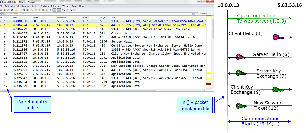
Figure 3.17 – TLS handshake protocol
Here, we can see a TCP connection open in packets 1 to 3, the SSL negotiation in packets 4 to 12, and that traffic starts to be transferred in packet numbers 13 and higher.
The first two packets in the negotiation are Client Hello and Server Hello, which are used to establish security capabilities between the two peers. Let's look at the first packet in the TLS handshake, which is packet 4 – the Client Hello packet. The client and the server agree on the protocol version, cipher suite, session ID, and completion method:
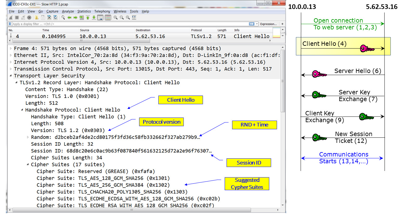
Figure 3.18 – TLS negotiation – Client Hello
The client and the server also generate and exchange two nonces (RND in the preceding diagram).
Important Note
Nonce is an arbitrary number that should be used just once in cryptographic communication. The term refers to a random number that is generated for a specific use. The term comes from number used once or number once.
Following the Client Hello message, the server answers with a Server Hello. This is shown in the following diagram:
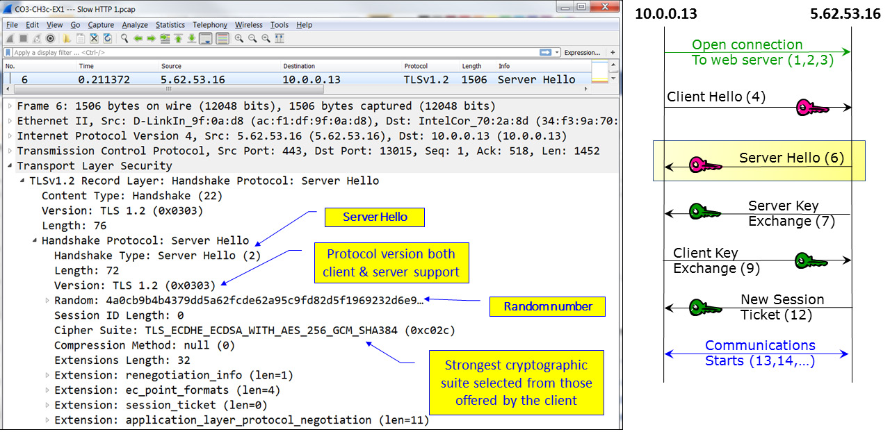
Figure 3.19 – TLS negotiation – Server Hello
In the Server Hello message, we can see that the cryptographic suite is AES-256 with SHA-384 and that the agreed version is TLSv1.2, with no compression.
In the next packet, as shown in the following diagram, a certificate is sent from the server to the client. This packet is called Certificate, Server Key Exchange, Server Hello Done:
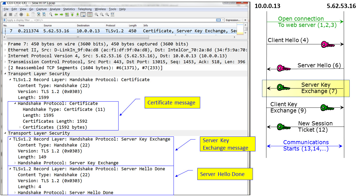
Figure 3.20 – TLS negotiation – Certificate, Server Key Exchange, Server Hello Done
Here, we can see that the TLS message contains three parts: Certificate, which contains a certificate that's 1,592 bytes, Server Key Exchange, which contains the signature algorithms and the public key, and Server Hello Done, which indicates the end of the server messages.
The next packet, as shown in the following diagram, is the Client Key Exchange. In this packet, if RSA is used, the client sends a pre-master secret to generate symmetric crypto keys and encrypts them with the server's public key. The client also sends a Change Cipher Spec message, and the client copies the pending Cipher Spec into the current Cipher Spec:
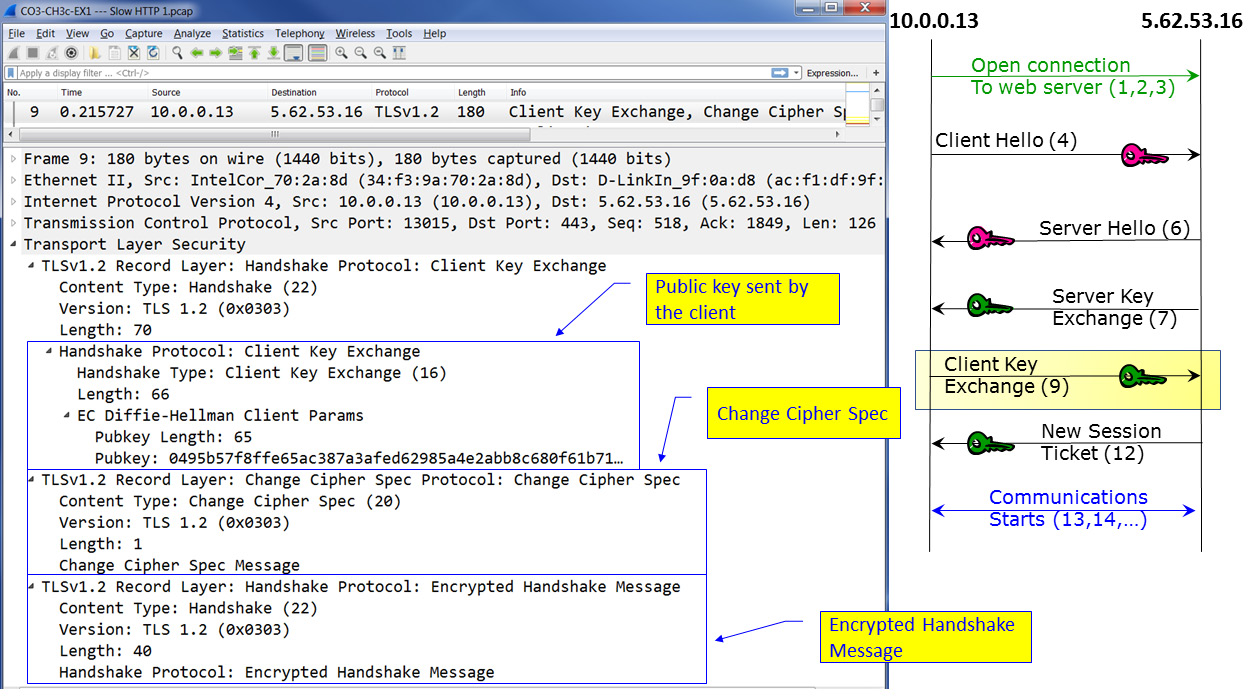
Figure 3.21 – TLS negotiation – Client Key Exchange
At this stage, the session negotiation is complete, but there might be additional messages, especially in later versions of TLS.
In our example, as shown in the following diagram, we can see a New Session Ticket message:
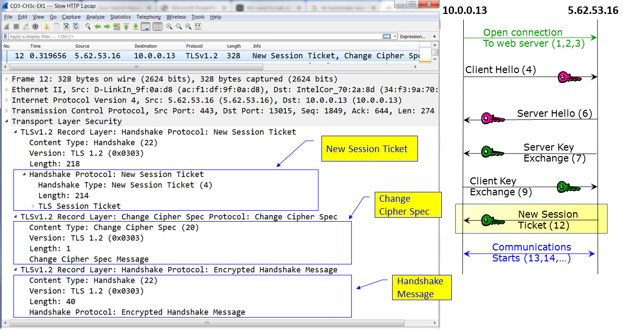
Figure 3.22 – TLS messages – New Session Ticket
Here, this message is sent by the server, telling the client to use a new ticket that includes new cipher parameters. The client should start using the new ticket as soon as possible after it verifies the server's Finished message for new connections.
SSL/TLS is also used in the encryption of other protocols, such as Secure File Transfer Protocol (S-FTP), Secure Shell (SSH) for connecting remotely to communications devices, Secure SIP (SIPS) and Secure RTP (SRTP) for securing telephony and multimedia sessions, and other protocols. We will discuss these protocols later in this book.
Network security components – RADIUS/TACACS+, FWs, IDS/IPSs, NAC, and WAFs
In this section, we will provide short descriptions of various network security devices and their functionality.
Firewalls
Firewalls provide the following features:
- Packet filtering forwards or drops sessions based on Layer 3 and Layer 4 information. This mechanism is the easiest one to break.
- Network Address Translation (NAT) is used to translate outgoing packets from internal to external internet addresses. This mechanism provides security as a side effect but is not considered to be a security mechanism.
- Stateful inspection watches the directions of TCP connections or UDP sessions that are opened through it, not only the Layer 3 and Layer 4 information. This method provides more security for the firewall.
In addition to this, most modern firewalls can provide additional mechanisms, depending on licensing:
- Intrusion detection and prevention (IDPS): This can discover and block traffic that comes in suspicious patterns.
- Application awareness: The ability to check upper layers protocols, including malicious traffic transferred through innocent protocols.
- Sandboxes: These can run delivered files before they are downloaded to the user's devices.
- Artificial intelligence (AI): This is a feature with the ability to self-learn network behavior and react to it.
Firewalls are the basic network protection devices in every network and they can be used in several places:
- Perimeter firewalls: To protect against risks coming from external networks, including the internet.
- Data center firewalls: These are placed between the user's network and the data center to protect against risks coming from users risking the information on the organization's servers.
- Core firewalls: These are used to separate the organization's network departments, if required, and provide higher-level security to the organization's departments that require it.
Deciding on which features to use depends on technical, economic, and business considerations. It also depends on the firewall's location.
RADIUS, NAC, and other authentication features
Remote Authentication Dial In User Service (RADIUS) was defined in RFC 2138 (IETF, June 2000). RADIUS was illustrated earlier in this chapter in Figure 3.9. A RADIUS server implements AAA – that is, authentication, authorization, and accounting.
Since the RADIUS protocol is from 2000, there are new services that have replaced it, with the most popular being TACACS+ and Diameter. However, RADIUS is still widely used to provide AAA services.
Web application firewalls (WAFs)
WAFs were created to protect against vulnerabilities coming from web servers, such as SQL injection, cross-site scripting, cross-site request forgery, DNS attacks, and more. The common denominator of these attacks is using a user's activity to inject malicious code into their end device, or using DNS attacks to forward the users to websites that will inject the malicious code.
In cross-site attacks, which are usually referred to as cross-site scripting (XSS), a web server is used to browse. Then, the web server injects a malicious script into our end device (PC, laptop, and so on).
SQL injection (SQLi) is an attack that tries to inject SQL language commands into a SQL application to get or change database content.
DNS attacks try to confuse the clients, mostly to cause them to open sessions to malicious websites that will damage them.
Unlike the basic firewall feature, which allows or blocks traffic based on its source, destination, and directions, and IDS/IPS, which discovers malicious patterns in simple web filters that forward or block traffic from specific websites, WAFs look at the content of the web applications and filter the code they run, so they are used in addition to the other protection mechanisms.
Summary
In the first two chapters of this book, we talked about network architecture and protocols, which brought us to this chapter, where we talked about security protocols, and how and where they are used to protect our networks.
At this point, we understand how different forms of encryption and authentication protocols work, as well as the major protocols that work in communications networks.
In the next chapter, we will talk about tools and methods for attacking networks and network protocols so that we can learn how to protect against them.
Questions
Answer the following questions to test your knowledge of this chapter:
- How are asymmetric encryption protocols used for encryption?
- Two public keys and two private keys are used to establish communications.
- The public key is used to encrypt the data, while the private key is used to decrypt the data
- The private key is used to encrypt the data, while the public key is used to decrypt the data.
- The same key is used for encryption and decryption; the difference is in the way they're used.
- What is integrity?
- Keeping information secret from unauthorized users
- Verifying the identity of the communication peers
- Keeping information unchanged through transmission
- Keeping the user's identity safe
- What is confidentiality?
- Keeping information hidden from unauthorized users
- Keeping the information secret from unauthorized users
- Keeping the information unchanged during transmission
- Protecting data from theft
- How are asymmetric encryption protocols used for encryption?
- Two public keys and two private keys are used to establish communications.
- The public key is used to encrypt the data, while the private key is used to decrypt the data..
- The private key is used to encrypt the data, while the public key is used to decrypt the data.
- The same key is used for encryption and decryption; the difference is in the way they're used.
- What is a hash function and what is it used for?
- A small key used for authentication
- A variable-length string that is produced from a variable-length block of data that's used for encryption
- A fixed-length string of data produced from a variable-length block of data to keep messages secret
- A fixed-length string of data produced from a variable-length block of data to keep message integrity
- What is the EAP protocol?
- A framework for defining user access to a network that can use various types of authentication methods
- A framework that establishes a complete set of protocols for user access to the network
- An access protocol that enables authentication and encryption through user networks
- A part of SSL/TLS that involves establishing a secure connection through the internet
- What is a certificate?
- A certification stating that a private key is legitimate.
- This is provided by a CA to the web server owner to prove the identity of the clients.
- This is provided by a CA to the client connecting to the web server to prove their identity.
- This is provided to the client and the server to establish connectivity.
- What is the difference between the tunnel and transport modes in IPSec?
- Tunnel mode is used between clients, while transport mode is used between servers.
- Tunnel mode is encrypted, while transport mode is not.
- Tunnel mode works with ESP, while transport mode works with AH.
- Tunnel mode adds an external IP header that is used to route the IPSec packets through the internet, while transport mode uses the original IP header.