
Chapter 12
Introduction to Business Continuity Clustering
Having a high-availability cluster is a good thing to prevent disasters from causing major problems with the continuity of your business. Sometimes, however, one cluster is not enough. What if, for example, a flood or an earthquake wipes out an entire site? In that case an ordinary cluster won’t help you. Especially for these kinds of situations, Novell has launched the Business Continuity Clustering (BCC) solution. This solution provides a true cluster of clusters. In this chapter BCC is introduced from a high-level overview perspective.
The goal of Business Continuity Clustering is to connect and synchronize information between clusters. At the time of writing this book, a maximum of four clusters is supported. In the 1.0 version, these need to be NetWare clusters; in BCC version 1.1, NCS 1.8 on Linux is supported as well. The clusters that are synchronized with BCC are often located at separate geographic sites. If one of the clusters goes down, the other clusters can take over the workload. In this way, nonstop access to mission-critical data and resources is guaranteed.
BCC is tightly integrated with eDirectory and synchronizes information between two to four clusters using eDirectory. For this purpose, Identity Manager, formerly known as DirXML, is used. Identity Manager is a Novell product that is used to synchronize information between different data sources. Originally, the purpose of Identity Manager was to synchronize, for example, between an eDirectory environment and an Active Directory environment, a PeopleSoft data store and many other applications, but it can be used to synchronize information within the same eDirectory structure as well. This is exactly the way BCC is using Identity Manager.
When a BCC solution is operational, services, configurations, and essential data can be migrated between two clusters with just one click. In fact, it is as easy as migrating a clustered resource within a Novell Cluster Services (NCS) environment where no synchronization with external resources takes place. In fact, BCC works a lot like NCS from an administrative perspective. There is, however, one major difference: Because it involves a lot of traffic and the results of a failover are rather severe, there is no such thing as automatic failover. You will always need to migrate BCC resources manually.
Speaking in a generic way, there are two methods for setting a high-availability environment if clusters at different physical sites are involved. The first solution is the so-called stretched cluster. In this solution, one cluster is created in which the nodes in the cluster are located in different geographical areas. All nodes are in the same eDirectory tree and in the same cluster. In this solution, the cluster heartbeat is happening over the WAN connection. Also the storage area network (SAN) is available across the WAN, with a disk array at both sites and both disk arrays connected by a dedicated high-speed fiber connection. In the setup of the cluster, nodes at site B must be configured to take over services from site A if an entire site goes down.
There are, however, some limitations to this solution. The first is that in an NCS environment, all nodes in the cluster need to be in the same subnet. Therefore, in a stretched cluster, you would be forced to use the same subnet across the WAN. Also, the eDirectory in which the stretched cluster is created needs to stretch the WAN because all cluster objects need to be in the same eDirectory container, and this might complicate eDirectory design. Another disadvantage is that you are still working with just one cluster, and that doesn’t offer the best possible fault tolerance; if you just have one cluster, you also have one single point of failure and that should be avoided.
A stretched cluster offers some advantages as well. Resources can fail over automatically, which is not possible in a cluster of clusters. Also, it is a lot easier to manage a stretched cluster than it is to manage separate clusters in a cluster of clusters.
The second solution to ensure high availability across sites is to build a cluster of clusters. In this solution, two different clusters are created and information is synchronized between the clusters, while both clusters are active at the same time. This is exactly what is happening in a BCC environment. In this scenario, there also needs to be replication of data blocks on the SAN; this is the responsibility of the SAN hardware. Other mirroring techniques also can be used to ensure availability of data across the different clusters in a cluster of clusters. For example, if no SAN is available, an rsync solution could be deployed to ensure data synchronization. If in a cluster of clusters, one of the sites would go down entirely, the entire cluster can fail over to the other site.
Note
Rsync is a solution that can be used to synchronize files or directories across the network. Rsync will be configured to synchronize files and/or directories at a specified time interval. It is not the best synchronization option available because delays will occur before changes are synchronized. For synchronization of small amounts of data, however, it is a good solution.
A cluster of clusters does offer some flexibility that is not available in a stretched cluster. These advantages are listed here:
![]() The change of LUNs in the SAN is minimized.
The change of LUNs in the SAN is minimized.
![]() There is no need to create eDirectory partitions that cross the WAN.
There is no need to create eDirectory partitions that cross the WAN.
![]() Each cluster can be in a separate eDirectory tree.
Each cluster can be in a separate eDirectory tree.
![]() Each cluster can have its own subnet.
Each cluster can have its own subnet.
![]() If one site fails, clustered resources can fail over to separate clusters. This feature is called multiple-site fan-out failover support.
If one site fails, clustered resources can fail over to separate clusters. This feature is called multiple-site fan-out failover support.
![]() There is no need to mirror SBD partitions between sites.
There is no need to mirror SBD partitions between sites.
The most important disadvantage of the cluster-of-clusters solution is that resource configurations must be kept in sync somehow. In a BCC environment, Identity Manager is used for this goal.
The main advantage Novell BCC has to offer as compared to a cluster of clusters is that synchronization of information between the clusters is happening automatically by using the Identity Manager eDirectory to eDirectory drivers. Novell BCC treats each of the separate sites in the cluster of clusters as a node in this metacluster. This allows an entire site to fail over to multiple sites. To add some level of automation to the failover process, BCC uses SAN hardware. The different Logical Units (LUNs) can be mirrored across the SAN. How exactly that happens depends entirely on the options offered by your SAN vendor. The entire configuration is managed with iManager, which allows for simplified management. If enhanced control and customization are needed, scripts can be used.
There are three scenarios in which BCC can be used:
![]() A two-site Business Continuity Cluster
A two-site Business Continuity Cluster
![]() A multiple-site Business Continuity Cluster
A multiple-site Business Continuity Cluster
![]() A low-cost Business Continuity Cluster
A low-cost Business Continuity Cluster
A short description of these three scenarios follows.
If BCC is used in a two-site solution, two different scenarios can be deployed. First, the remote site can be configured as a passive site that takes over services only if the primary site fails. If services need to be used at both sites, both sites can be active as well. In this scenario, either site can take over services from the other site if needed; you should, however, be aware that enough resources need to be present at both sites to allow for a smooth failover. The scenario in which both sites are active is the more realistic scenario for large companies.
In a large environment, BCC can support up to 32 nodes per site with a maximum of four sites. In this scenario, if a site fails the clustered resources can fan out failover between sites. To replicate data across the sites, the solutions offered by the SAN vendors need to be used, although host-based mirroring solutions such as rsync can be used as well.
Normally, a company would use a Fiber Channel SAN to ensure data availability across the different sites. If no Fiber Channel SAN is available, data block replication can be accomplished with iSCSI or rsync as well. This is ideal for test environments and environments where no budget is available for a Fiber Channel SAN; you should, however, be aware that such a solution does not offer the same performance level. In the rest of this chapter, you’ll learn how you can create your own BCC test environment.
This section describes how to build your own BCC test environment. Because when this was written, BCC 1.1, which supports Linux clusters, was not available yet, you will learn how to install BCC 1.0 in an Open Enterprise Server (OES) NetWare environment. With some modifications, this procedure will also apply to a BCC 1.1 environment. Before you begin, you must make sure that the following requirements are met:
![]() NetWare 6.5 Support Pack 2 or later is installed on all nodes in the cluster.
NetWare 6.5 Support Pack 2 or later is installed on all nodes in the cluster.
![]() Two to four clusters running Novell Cluster Services 1.7 or higher are installed.
Two to four clusters running Novell Cluster Services 1.7 or higher are installed.
![]() Each cluster must have a unique name.
Each cluster must have a unique name.
![]() To keep it simple, we recommend setting up the test environment with both clusters in the same tree; this will simplify the Identity Manager setup a great deal.
To keep it simple, we recommend setting up the test environment with both clusters in the same tree; this will simplify the Identity Manager setup a great deal.
The following procedure describes how to create a BCC environment based on two two-node clusters. In these clusters, iSCSI is used as the shared storage solution. As you will learn, in both clusters there is an iSCSI target that plays the role of the SAN in the environment.
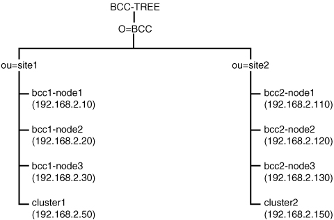
In this scenario, we will build one eDirectory tree with the name BCC-TREE, as shown in Figure 12.1. In this tree, two different Organizational Units (OUs) are created: site1 and site2. Both containers contain three servers, of which the first server functions as an iSCSI target. All other objects in the tree are not relevant for this setup.
Follow this procedure to create a BCC test environment:
1. Install Open Enterprise Server NetWare on all servers in the tree as illustrated in Figure 12.1. On all servers, make sure that at least Apache2 and iManager are installed. On bcc1-node1 and bcc2-node1, the iSCSI target software must be installed as well.
2. After installation of the operating system, make sure that time is synchronized properly between all servers. Then put a R/W-replica on all servers. For the purpose of this lab setup, it is not necessary to create a partition for the different locations. In a real-life situation you might want to do that.
3. If resources on your servers are limited, make sure that AFP, NFS, CIFS, and STARTX are disabled with a remark-sign in AUTOEXEC.NCF.
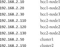
4. Update the hosts file on all servers. In the tree as described previously, you can use the following entries:
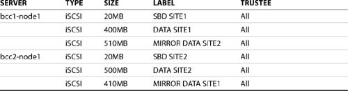
5. On the iSCSI target servers, load NSSMU and create three iSCSI partitions as in Table 12.1. Also make the appropriate server objects trustees of the iSCSI target object. Consult Chapter 7, “iSCSI,” for more details on the iSCSI setup.
6. On all servers that are going to be used as cluster nodes and iSCSI initiators, create a file with the name INITSTRT.NCF and give it the following contents:
7. Install the clusters for both sites. Complete the NCS installation procedure and check that NCS comes up on all servers. Next, remove the line where NCS is started by calling the LDNCS.NCF script from AUTOEXEC.NCF. This is because later in the procedure, you must make sure that the Identity Manager drivers have had enough time to synchronize before starting NCS or BCC.
BCC uses Identity Manager 2.0 to synchronize information across eDirectory trees or even within an eDirectory tree. At this stage, you need to perform a basic installation of Identity Manager 2.0. Everything that is needed is provided with the free Identity Manager 2.0 starter pack, which is part of Open Enterprise Server or which can be downloaded free from http://www.novell.com/download. Complete the following installation procedure on one server in each cluster you want to add to the BCC environment:
1. Mount the Identity Manager installation CD on bcc1-node2 (not on the iSCSI target, but on the first node that is a member of the cluster).
2. From the graphical user interface on the server, click Novell and then select Install (see Figure 12.2). In the list of installed products, click Add and browse to the products.ni file in the NetWare section on the Identity Manager installation CD. Then click OK twice to continue. This will start the Identity Manager installation procedure.
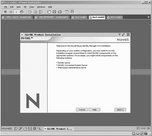
3. Click Next and then click I Accept to accept the terms of the license agreement. You will now see an overview of all components of an Identity Manager (formerly known as DirXML) environment. Notice that often the Identity Manager components are still referred to as DirXML components.
4. Click Next to enter the components screen. Make sure that all components are selected and then click Next to continue.
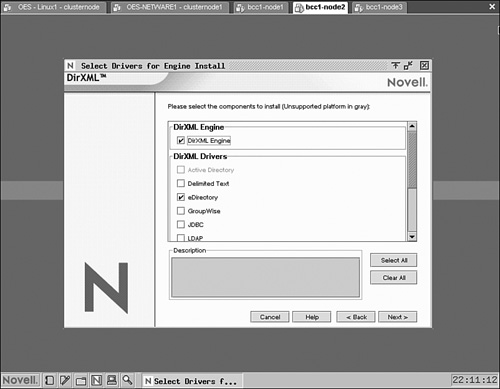
5. As shown in Figure 12.3, Identity Manager consists of an engine and drivers. The engine is always needed on an Identity Manager server; a driver is needed for each application that needs to be synchronized with. In this case, synchronization with external applications is not needed. Therefore, just select the eDirectory driver and click Next to continue. Both servers will need the DirXML Engine as well.
6. Ignore the message about activation of Identity Manager components and click OK to continue.
7. To extend the schema, enter the name and password of the admin user with sufficient permissions to perform this schema extension. This name must be entered in LDAP format, so enter cn=admin,o=bcc instead of .admin.bcc. Then click Next to proceed.
8. From the Components screen, click Next. Two more components screens will appear. Leave the default selection and click Next to continue. Then click Finish to start copying the Identity Manager files to your server.
9. If prompted that a newer file exists, choose never to overwrite newer files on your server.
10. When the installation has completed, click Close.
11. Restart your server when the installation of Identity Manager has completed.
Now that everything is in place and installed, just a few steps remain. First, BCC has to be installed. Then, the Identity Manager eDirectory drivers need to be configured to synchronize data between both clusters. After that, the final phase of the configuration can be completed: BCC has to be configured to enable failover between two to four clusters. In this section you’ll learn how to install the BCC product.
To install BCC, apply the following procedure:
1. Insert the BCC CD in a Windows workstation and run install.exe from the CD. Click Next and then I Accept to start the installation procedure.
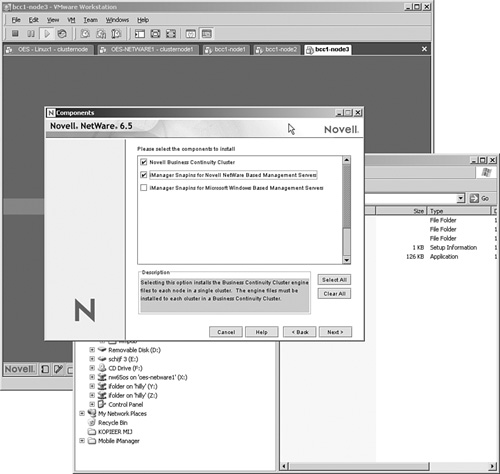
2. When asked what components to install, select Novell Business Continuity Cluster and iManager Snapins for Novell NetWare Based Management Servers, as shown in Figure 12.4. Then click Next twice.
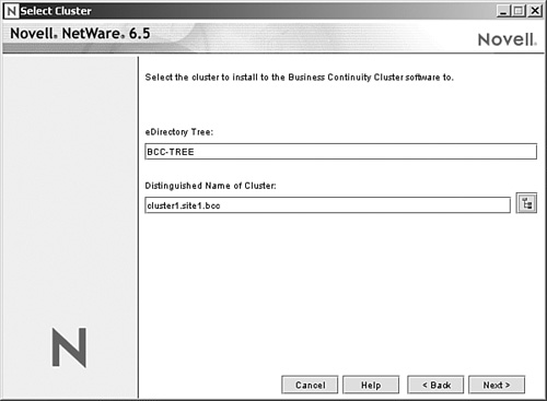
3. Now you need to enter the distinguished name of the first cluster object you want to add to the BCC environment (see Figure 12.5). Select cluster1 and then click Next to continue.
4. Make sure that all nodes in the cluster are selected, and click Next to continue.
5. Next, you need to select the NetWare server where you want to install the iManager snapins. Select bcc1-node2 and click Next to continue. This will install all required software to the nodes in the first cluster.
6. After installation, the line LDBCC.NCF is added to the AUTOEXEC.NCF file on all nodes in the cluster. Open the AUTOEXEC.NCF file and comment out this line with the REM statement or the pound sign (#).
7. Repeat the preceding steps for the other cluster.
Now that all required software components have been installed, it is time to start the real work. The first part of this is to configure the Identity Manager drivers. You need to configure Identity Manager on both sides of the cluster. On site1 the driver is responsible for keeping a copy of all relevant objects from site2, and on site2 the Identity Manager driver must make sure that all relevant objects from site1 are kept. For this purpose, you need to configure separate containers that function as a landing zone for the objects from the other site at both sites. In this example, we will work with ou=fromsite2.ou=site1.o=bcc and ou=fromsite1.ou=site2.o=bcc.
Note
The relevant snapins for management of BCC are not installed on all servers in your tree by default. From now on, we recommend that you connect only to the servers where the snapins are installed.
1. Before proceeding, make sure that the servers on which you want to configure iManager have an eDirectory replica of the partition they are in. Then start iManager at https://yourserver/nps.
2. Browse to DirXML Utilities and select New Driver. Then select In a New Driver Set and click Next to continue.
3. Enter the following information for the new Driver set and click Next to continue (see Figure 12.6):

![]() Context:
Context: site1.bcc
![]() Server:
Server: bcc1-node2.site1.bcc
![]() Uncheck the Create a New Partition on This Driver Set box
Uncheck the Create a New Partition on This Driver Set box
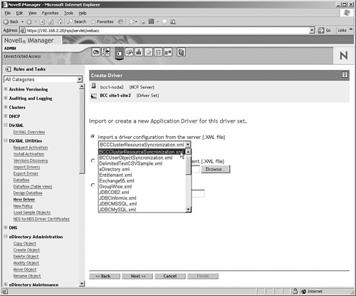
4. In the next screen you need to create the driver. Creating an Identity Manager driver all by yourself is a daunting task, so select Import a Driver Configuration from the Server (.XML File) as shown in Figure 12.7, and from the drop-down list select BCCClusterResourceSynchronization.xml. Then click Next to continue.
5. Now you have to enter specific properties for the driver. Use the following information:
![]() Driver name:
Driver name: site12site2 driver.
![]() Name of the SSL certificate:
Name of the SSL certificate: none.
Note
If you are synchronizing between two different eDirectory trees, make sure that you do select an SSL certificate here. In this scenario, however, we are synchronizing within the same eDirectory tree, and therefore an SSL certificate is not needed.
![]() Name of other DirXML node:
Name of other DirXML node: 192.168.2.120 (this should be the IP address of the node in cluster 2 where you have installed the Identity Manager software).
![]() Port number for this driver:
Port number for this driver: 2002.
![]() Full distinguished name of this cluster:
Full distinguished name of this cluster: cluster1.site1.bcc.
![]() Full distinguished name of the other cluster:
Full distinguished name of the other cluster: cluster2.site2.bcc.
![]() Context where cluster-enabled pool and volume objects will be synchronized for this cluster:
Context where cluster-enabled pool and volume objects will be synchronized for this cluster: fromsite2.site1.bcc.
![]() Parent container context of cluster-enabled pool and volume objects for other cluster:
Parent container context of cluster-enabled pool and volume objects for other cluster: site2.bcc. This is the context in the other tree where the cluster-enabled pools and volumes reside. Normally, this is the same context as the context where your cluster object is created.
![]() Name of the other cluster’s tree:
Name of the other cluster’s tree: BCC-TREE.
6. Now select Define Security Equivalences and browse to the admin object in your tree. This ensures that the Identity Manager driver has sufficient rights to create objects in your tree when synchronizing between two clusters. Then click Next to continue.
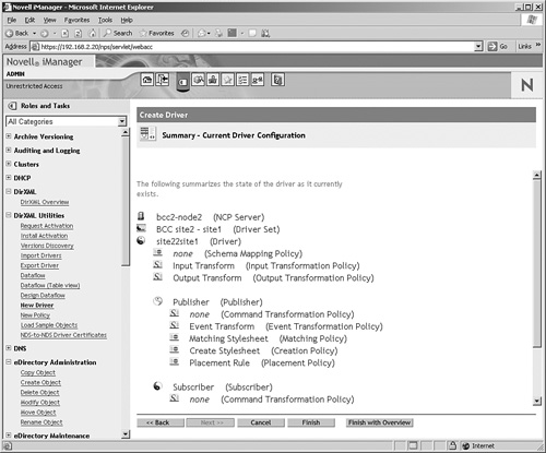
7. You will now see a summary of the current driver configuration (see Figure 12.8). The summary gives an overview of all eDirectory objects that are created. From this overview, click Finish to add the driver to your network.
Tip
For novice users, the Identity Manager summary view does not provide a great level of detail. To get more insight in how the driver is configured, click Finish with Overview.
8. Repeat all tasks to create an Identity Manager driver in site2 as well. Make sure that in the driver details screen, the following information is used:
![]() Driver name:
Driver name: site22site1 driver.
![]() Name of the SSL certificate:
Name of the SSL certificate: none.
![]() Name of other DirXML node:
Name of other DirXML node: 192.168.2.20 (this should be the IP address of the node in cluster 1 where you have installed the Identity Manager software).
![]() Port number for this driver:
Port number for this driver: 2002.
![]() Full distinguished name of this cluster:
Full distinguished name of this cluster: cluster2.site2.bcc.
![]() Full distinguished name of the other cluster:
Full distinguished name of the other cluster: cluster1.site1.bcc.
![]() Context where cluster-enabled pool and volume objects will be synchronized for this cluster:
Context where cluster-enabled pool and volume objects will be synchronized for this cluster: fromsite1.site2.bcc.
![]() Parent container context of cluster-enabled pool and volume objects for other cluster:
Parent container context of cluster-enabled pool and volume objects for other cluster: site1.bcc. This is the context in the other tree where the cluster-enabled pools and volumes reside. Normally, this is the same context as the context where your cluster object is created.
![]() Name of the other cluster’s tree:
Name of the other cluster’s tree: BCC-TREE.
Now that the Identity Manager drivers have been created, they still need to be started. The tasks described next need to be performed on both servers where Identity Manager is installed:
1. From iManager, select DirXML, DirXML Overview. Then select Search Entire Tree and click the Search button. This will display a screen as shown in Figure 12.9.

2. Click the stop sign on the driver and select Start Driver. The driver will now be started. If it has started successfully, you will see a yin/yang-icon on the driver to indicate that it is running. After the first driver is up, do the same for the second driver.
Tip
If you are not really into Identity Manager, troubleshooting it is difficult. If you can’t get the drivers synchronizing to each other and you are sure that you have completed all steps as listed in this procedure, we recommend that you delete the drivers and create new drivers. This will be a lot easier than troubleshooting where exactly you have made a mistake in configuring the IDM drivers.
3. Only after the Identity Manager drivers have started successfully, start Novell Cluster Services with the LDNCS.NCF file on all nodes in both clusters. If you have created the INITSTRT.NCF file as described previously, don’t forget to run it before you start the cluster.
4. When NCS has loaded, start BCC by running the LDBCC.NCF file on all nodes in both clusters. This should get your BCC environment up and running.
Now that all the required software is active, it is time to make some modifications to all related eDirectory objects. First, you will learn how to enable Business Continuity Features for both clusters:
1. Start iManager on the node in cluster 1 that is configured with Identity Manager. Then select Clusters, Cluster Options and browse to cluster 1.
2. Click Properties, and then select the Business Continuity tab.
3. Click the Enable Business Continuity Features check box as shown in Figure 12.10 and click OK.
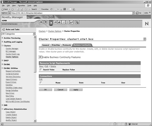
4. Repeat this procedure for the other cluster in your setup.
Now that BCC has been enabled for both clusters, you need to set up authentication between the two clusters. To make this possible, you must add the administrator username and password that your cluster will use to connect to the other cluster. Of course, this needs to happen on both clusters.
Tip
If you have problems setting up the connection between both clusters, always make sure that the Identity Manager driver is active first. Without a working Identity Manager driver, you can’t get a working BCC connection between two clusters. Use the DirXML, DirXML Overview option in iManager to monitor current activity of Identity Manager drivers.
1. From the Business Continuity properties tab of the selected cluster, in the Connections section select the other cluster and click Edit (see Figure 12.11).
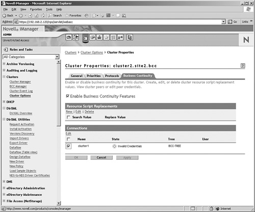
2. Enter the complete username including the eDirectory context of your admin user and its password.
3. Repeat this step for the other cluster.
Tip
If the other cluster does not appear in the list of possible peer clusters, make sure that the following conditions have been met:
Tip
Still having problems setting up the connection? You can use the cluster credentials command from the BCC console on the servers to set up the connection as well. On bcc1-node 2 enter the command cluster credentials cluster2. Next, enter the distinguished admin name and password. Repeat this procedure on the other node by using the command cluster credentials cluster1.
Next, some objects need to be created in the clusters and they need to be configured for failover. The following procedure shows how to create a volume pool resource and how this object is enabled for failover in a BCC environment:
1. On bcc1-node2, load NSSMU. Start NSSMU, select pools, and press Insert to create a new pool. Give the pool the name site1pool and press Enter.
2. Select the appropriate partition on the iSCSI shared disk device and press Enter. Next, accept the default for the partition size and press Enter.
3. Accept all default values for the pool object and provide it a unique IP address. Make sure that the IP address can be resolved to the name of this pool in the /etc/hosts file on your server. Then click Create to create the pool.
4. Now create a volume named site1vol in the pool you have just created.
5. Repeat this procedure to also create a pool and volume object for site2 in your cluster.
Next, you have to make the partitions available across the clusters in your network. For this purpose, you need to mirror the partitions. The next procedure shows how to do this with NSSMU:
1. Load NSSMU on bcc1-node2 and select Partitions.
2. Select the NSS partition with the site1pool pool on it.
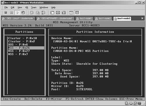
3. Press F3 to display mirror options. It will show a list of all available partitions as shown in Figure 12.12. Now select the right partition object. You need to look at the partition ID to determine which partition you need. In the Device Name value, each partition has a name like [V060-A3-D3:0]. Determine the device name of the partition on the local server that you want to mirror, and next determine the device name of the partition on the other server you have just created. That leaves two devices available for mirroring. If you created a 400MB partition on the local server and, directly after that, the 410MB partition on the other server to serve as a partition for mirroring, you have to look at the local device name plus 1; if the local device name is [V060-A3-D3:0], the device name you need on the other server is [V060-A3-D4:0]. Select this partition, press Enter, and when asked Create Mirror on Shared Device? select Yes to continue. In a few seconds the mirror will be established. You can see this on the partition object as well because it will have a mirror ID added to it.
4. Use the MIRROR STATUS command on the console of your server to monitor the mirroring process. Wait for it to complete and then continue—this can take a few minutes—with the next phase of the procedure.
With the creation of the pool objects, for both pools a virtual server object is created in your clusters automatically. In the next phase of this procedure, we need to set up the virtual server object for use in your BCC environment:
1. In iManager, select Cluster, Cluster Options. Then select the SITE1POOL_SERVER object and click Properties.
2. Activate the Business Continuity tab, and there check the Enable Business Continuity Features check box.
3. Now from the Resource Script Replacements section, click New.
4. For the search value enter 192.168.2.51 (the address of the local cluster-enabled pool object), and for the replace value enter 192.168.2.152. The second IP address is the IP address that will be added to the pool object you have just created after it fails over successfully.
5. Now from the list of Available Peer Clusters, select both cluster1 and cluster2 and click OK (see Figure 12.13). You have just BCC-enabled your cluster pool object.

6. Repeat this procedure for the SITE2POOL_SERVER object. On this object, use 192.168.2.151 and 192.168.2.52 as the search and replace values.
You have just set up your cluster-enabled pool objects for BCC. Now it is time to test whether it works. For this purpose, you are going to select the CLUSTER2POOL_SERVER object and migrate it to the other cluster.
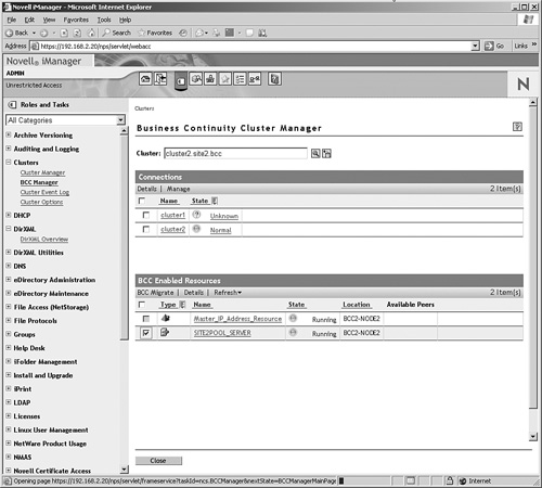
1. From iManager, select BCC Manager and select cluster2.
2. Check the SITE2POOL_SERVER object and click BCC Migrate to migrate. This allows you to migrate the resource to any cluster that is available from the list of available peers (see Figure 12.14).
If you need more than a cluster, Novell Business Continuity Cluster Services is a great solution; it allows you to create a cluster of clusters. In this chapter you read about the components BCC is made of, and you created a simple BCC lab setup. Although it is simple, it involves a lot of steps to be performed. Nevertheless, after it works, BCC offers a great solution for optimized fault tolerance within large enterprise environments. Watch out for BCC version 1.1 because it will also allow you to synchronize between OES Linux clusters.