
In this introductory chapter, you'll learn about the main themes — domain-specific languages (DSLs), model-driven development (MDD), and the Unified Modeling Language (UML) — and how they apply to the Visual Studio 2010 Ultimate. As part of this discussion, you'll learn what Microsoft has to say on those subjects, as well as some impartial views from the authors.
This chapter examines the evolution of distributed computing architectures — from simple object-oriented development, through component and distributed-component design, to the service-oriented architectures (SOAs) — that represent the current state of the art.
This chapter wraps up with a brief glimpse at the new architecture tools in Visual Studio 2010. New modeling tools, as well as support for the most common Unified Modeling Language diagrams, have been added to Visual Studio 2010, making the architecture tools first-class citizens in the product.
Let's begin by first establishing the case for even undertaking visual modeling — or visual design — in the first place.
Two elementary questions immediately come to mind. Why design at all, rather than just code? Why design visually?
To answer the first question, consider the common analogy of building complex physical structures, such as bridges. Crossing a small stream requires only a plank of wood — no architect, no workers, and no plans. Building a bridge across a wide river requires a lot more — a set of plans drawn up by an architect so that you can order the right materials, planning the work, communicating the details of the complex structure to the builders, and getting a safety certificate from the local authority. It's the same with software. You can write a small program by diving straight into code, but building a complex software system will require some forethought. You must plan it, communicate it, and document it to gain approval.
Therefore, the four aims of visual design are as follows:
To help you visualize a system you want
To enable you to specify the structure or behavior of a system
To provide you with a template that guides you in constructing a system
To document the decisions you have made
Traditionally, design processes like the Rational Unified Process have treated design and programming as separate disciplines, at least in terms of tools support. You use a visual modeling tool for design, and a separate integrated development environment (IDE) for coding. This makes sense if you treat software development like bridge building, and assume that the cost of fixing problems during implementation is much higher than the cost of fixing those problems during design.
For bridges, that is undoubtedly true. But in the realm of software development, is it really more costly to change a line of code than it is to change a design diagram? Moreover, just as bridge designers might want to prototype aspects of their design using real materials, so might software designers want to prototype certain aspects of their design in real code.
For these reasons, the trend has been toward tools that enable visual design and coding within the same environment, with easy switching between the two representations, thus treating design and coding as essentially two views of the same activity. The precedent was set originally in the Java space by tools such as Together-J and, more recently, in the .NET space by IBM-Rational XDE, and this approach has been embraced fully by the Visual Studio 2010 Ultimate.
Now, let's tackle the second question. If the pictorial design view and the code view are alternative but equivalent, representations, then why design visually at all? The answer to that question is simple: A picture paints a thousand words. To test that theory, just look at the figures in this chapter and imagine what the same information would look like in code. Then imagine trying to explain the information to someone else using nothing but a code listing.
As mentioned, Microsoft's Visual Studio 2010 modeling strategy is based on a couple of ideas:
Domain-specific languages (DSLs)
Model-driven development (MDD)
These topics together comprise Microsoft's new vision for how to add value to the software development process through visual modeling.
First, let's set the scene. The Object Management Group (OMG) has a licensed brand called Model-Driven Architecture (MDA). MDA is an approach to MDD based on constructing platform-independent UML models (PIMs) supplemented with one or more platform-specific models (PSMs). Microsoft also has an approach to MDD, based not on the generic UML but rather on a set of tightly focused DSLs. This approach to MDD is part of a Microsoft initiative called software factories, which, in turn, is part of a wider Dynamic Systems Initiative.
Note
If you would like a more in-depth exploration of software factories, check out the book, Software Factories: Assembling Applications with Patterns, Works, Models and Tools, written by Keith Short, Jack Greenfield, Steve Cook, and Stuart Kent (Indianapolis: Wiley, 2004).
As a software designer, you may be familiar with the "code-generation" features provided by UML tools such as Rational Rose and IBM-Rational XDE. These tools typically do not generate "code" at all but merely "skeleton code" for the classes you devise. So, all you get is one or more source files containing classes populated with the attributes and operation signatures that you specified in the model.
Note
The words "attribute" and "operation" are UML terminology. In the .NET world, these are often referred to as "field" and "method," respectively.
As stated in Microsoft's modeling strategy, this leads to a problem:
"If the models they supported were used to generate code, they typically got out of sync once the developers added other code around the generated code. Even products that did a good job of 'round tripping' the generated code eventually overwhelmed developers with the complexity of solving this problem. Often, these problems were exacerbated, because CASE tools tried to operate at too high a level of abstraction relative to the implementation platform beneath. This forced them to generate large amounts of code, making it even harder to solve the problems caused by mixing handwritten and generated code."
The methods that are generated for each class by UML code-generation tools typically have complete signatures but empty bodies. This seems reasonable enough, because, after all, the tool is not psychic. How would it know how you intend to implement those methods? Well, actually, it could know.
UML practitioners spend hours constructing dynamic models such as statecharts and sequence diagrams that show how objects react (to method invocations) and interact (invocate methods on other objects). Yet, that information, which could be incorporated into the empty method bodies, is lost completely during code generation.
Note
Note that not all tools lose this kind of information during code generation, but most of the popular ones do. In addition, in some cases, UML tools do generate code within method bodies—for example, when you apply patterns using IBM-Rational XDE—but, in general, the point is valid.
Why do UML tools generally not take account of the full set of models during code generation? In part, it's because software designers do not provide information on the other models with sufficient precision to be as useful as auto-generated method bodies. The main reason for that is because the notation (UML) and tools simply do not allow for the required level of precision.
What does this have to do with MDD? Well, MDD is all about getting maximum value out of the modeling effort, by taking as much information as possible from the various models right through to implementation. As Microsoft puts it:
"Our vision is to change the way developers perceive the value of modeling. To shift their perception that modeling is a marginally useful activity that precedes real development; to recognition that modeling is an important mainstream development task. . ."
Although the example of UML dynamic modeling information finding its way into implemented method bodies was useful in setting the scene, don't assume that MDD is only (or necessarily) about dynamic modeling. If you've ever constructed a UML deployment model and then tried to do something useful with it — such as generate a deployment script or evaluate your deployment against the proposed logical infrastructure — you will have seen how wasted that effort has been, other than to generate some documentation.
So, what's the bottom line? Because models are regarded as first-class development artifacts, developers write less conventional code, and development is, therefore, more productive and agile. In addition, it fosters a perception among all participants — developers, designers, analysts, architects, and operations staff — that modeling actually adds value to their efforts.
UML fails to provide the kind of high-fidelity domain-specific modeling capabilities required by automated development. In other words, if you want to automate the mundane aspects of software development, then a one-size-fits-all generic visual modeling notation will not suffice. What you need is one or more DSLs (or notations) highly tuned for the task at hand — whether that task is the definition of Web services, the modeling of a hosting environment, or traditional object design.
Warning
A DSL is a modeling language that meets certain criteria. For example, a modeling language for developing Web services should contain concepts such as Web methods and protocols. The modeling language should also use meaningful names for concepts, such as fields and methods (for C#), rather than attributes and operations. The names should be drawn from the natural vocabulary of the domain.
The DSL idea is not new, and you may already be using a DSL for database manipulation (it's called SQL) or XML schema definition (it's called XSD).
Visual Studio 2010 Ultimate embraces this idea by providing the capability to create DSLs for specific tasks. DSLs enable visual models to be used not only for creating design documentation, but also for capturing information in a precise form that can be processed easily, raising the prospect of compiling models into code.
Note
The only DSL that Visual Studio 2010 Ultimate provides "out of the box" is the UML support. Users have the capability to create their own DSLs using the DSL toolkit.
In that context, "your own problem domain" need not be technology-focused (such as how to model Web services or deployment infrastructures) but may instead be business-focused. You could devise a DSL highly tuned for describing banking systems or industrial processes.
The design features provided by Visual Studio 2010 Ultimate have been influenced not only by Microsoft's vision for MDD but also by a technological evolution from object-based architectures, through (distributed) component-based architectures, to the SOAs, that represent the current best practice in distributed system design.
When object-oriented programming (OOP) became popular in the mid-1990s, it was perceived as a panacea. In theory, by combining state (data) and behavior (functions) in a single code unit, you would have a perfectly reusable element — a cog to be used in a variety of machines.
The benefit was clear. There would be no more searching through thousands of lines of code to find every snippet that manipulated a date — remember the Y2K problem? By encapsulating all date-manipulation functionality in a single Date class, you would be able to solve such problems at a stroke.
Object orientation turned out not to be a panacea after all, for many reasons, including (but not limited to) bad project management (too-high expectations), poor programming (writing procedural code dressed up with objects), and inherent weaknesses in the approach (such as tight coupling between objects).
For the purposes of this discussion, let's concentrate on one problem in particular, which is the style of reuse that objects encouraged — what you might call copy-and-paste reuse.
Consider the following copy-and-paste reuse scenario. You discover that your colleague has coded an object — call it Book — that supports exactly the functionality you need in your application. You copy the entire source code for that object and paste it into your application.
Yes, it has saved you some time in the short term, but now look a little farther into the future.
Suppose the Book class holds fields for Title and ISBN, but in your application, you now need to record the author. You add a new field into your copy of the Book source code, and name that field Author.
In the meantime, your colleague has established the same need in his application, so he, too, modifies the Book source code (his copy) and has the foresight to record the author's name using two fields: AuthorSurname and AuthorFirstname.
Now, the single, reusable Book object exists in two variants, both of which are available for a third colleague to reuse. To make matters worse, those two variants are actually incompatible and cannot easily be merged, thanks to the differing representations of the author name.
Once you've compiled your application, you end up with a single executable file (.exe) from which the Book class is indivisible, so you can't change the behavior of the Book class — or substitute it for your colleague's variant — without recompiling the entire application (if you still have the source code, that is!).
As another example (which will be continued through the next sections), imagine you're writing a technical report within your company. You see one of the key topics written up in someone else's report, which has been sent to you by email. You copy that person's text into your document, change it a little, and now your company has two slightly different descriptions of the same topic in two separate reports.
At this point, you might be shouting that individual classes could be compiled separately and then linked together into an application. Without the complete source code for the application, you could recode and replace an individual class without a full recompilation; just link in the new version.
Even better, how about compiling closely related (tightly coupled) classes into a single unit with only a few of those classes exposed to the outside world through well-defined interfaces? Now the entire sub-unit — let's call it a component — may be replaced with a newer version with which the application may be relinked and redeployed.
Better still, imagine that the individual components need not be linked together prior to deployment, but may be linked on-the-fly when the application is run. Then there is no need to redeploy the entire application; just apply the component updates. In technological terms, this describes DLLs (for those with a Microsoft background) or JAR files (for the Java folks). And, in .NET terms, this describes assemblies.
Continuing with the nonprogramming analogy, consider hyperlinking your technical report to the appropriate section of your colleague's report, and then distributing the two documents together, rather than copying your colleague's text into your document.
Continuing with this line of thought, imagine that the components need not be redeployed on client devices at all. They are somehow just available on servers, to be invoked remotely when needed at run-time.
In the nonprogramming example, consider not having to distribute your colleague's report along with your own. In your own report, you would simply hyperlink to the relevant section in your colleague's document, which would be stored — and would remain — on an intranet server accessible to all recipients.
One benefit of this kind of remote linking is that the remote component may be adapted without having to be redeployed to numerous clients. Clients would automatically see the new improved version, and clients constrained by memory, processing power, or bandwidth need not host the components locally at all.
This leads to a distributed component architecture, which, in technology terms, means Distributed Common Object Model (DCOM), Common Object Request Broker Architecture (CORBA), or Enterprise Java Beans (EJB). All of these technologies support the idea of a component (or object) bus via which remote operations may be discovered and invoked. In Figure 1-1, the component bus is indicated by the grayed-out vertical bar.

Of course, as remote components are modified, you must ensure that none of the modifications affect the abilities of clients to use those components, which is why you must make a distinction between interfaces and implementations:
Interface — A component interface defines the contract between that component and the clients that use it. This contract must never be broken, which, in practice, means that existing operations may not have parameters added or taken away, though it may sometimes be permissible to add new operations. The semantics (or behavior) of the operation should remain unchanged.
Implementation — A component implementation may be changed at will in terms of the use of an underlying database, the algorithms used (for example, for sorting), and maybe even the programming language in which the component is written, as long as the behavior is unaffected as far as the client is concerned.
This distinction between interface and implementation raises some very interesting possibilities. For example, a single component implementation (for example, Bank) may support several interfaces (for example, AccountManager and MoneyChanger), whereas the MoneyChanger interface may also be supported by another implementation (for example, PostOffice).
Moreover, the underlying implementations may be provided by various competing organizations. For example, you could choose your bank account to be managed by the Bank of BigCity or the National Enterprise Bank, so long as both supported the AccountManager interface.
What's wrong with the distributed components approach?
To start with, the same underlying concepts have been implemented using at least three different technologies: the OMG's CORBA, Microsoft's DCOM, and Sun Microsystems' EJB. Though comparable in theory, these approaches require different programming skills in practice and do not easily interoperate without additional bridging software such as DCOM/CORBA bridges and RMI-over-IIOP.
Furthermore, distributed component technologies encourage stateful intercourse between components by attempting to extend the full object-oriented paradigm across process and machine boundaries, thereby triggering a new set of challenges (such as how to manage distributed transactions across objects), requiring yet more complex technology in the form of the CORBA Transaction Service, or the Microsoft Transaction Server (MTS).
To a certain extent, an SOA alleviates these problems by keeping it simple — by making the services stateless, if possible, and by allowing services to be invoked using the widely adopted, standard over-the-wire protocol Simple Object Access Protocol (SOAP).
The architecture tools in Visual Studio 2010 Ultimate have undergone a large transformation. There are several new diagrams that can be used for modeling, as well as support for the most common UML diagrams. All of these new diagram options can be used to help you more fully understand the software system that is being built. These tools allow you to create models at different levels of detail, depending on your need.
This section provides a very brief overview of each of the new modeling diagrams. The chapters that follow in the book provide an in-depth look into each diagram type.
As mentioned previously, Visual Studio 2010 fully supports UML now, specifically UML 2.1.2. Only five UML diagrams are supported out-of-the-box:
Use case diagrams
Activity diagrams
Sequence diagrams
Component diagrams
Class diagrams
However, future releases of the product will add support for more UML diagrams.
There are other tools and diagrams, not related to UML, included with Visual Studio 2010 Ultimate. The Architecture Explorer can be used to understand the architecture of existing code, or of managed assemblies. Dependency graphs are used to provide a graphical view of the information from Architecture Explorer. Layer diagrams can be used to describe the logical architecture of your system and can even be used during the build process to enforce architecture considerations on the code base.
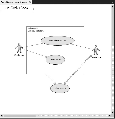
A use case diagram is a summary of who uses your application and what they can do with it. It describes the relationships among requirements, users, and the major components of the system.
Use case diagrams show the relationships between users (actors) and use cases within a system or application. They provide an overall view of how a system is used and the various roles and actions that take place within the system. Figure 1-2 shows an example of a use case diagram.
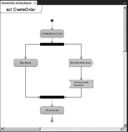
Use case diagrams can be broken down into activity diagrams. An activity diagram shows the software process as the flow of work through a series of actions. Figure 1-3 shows an example of an activity diagram.
Sequence diagrams display interactions between different objects. This interaction usually takes place as a series of messages between the different objects. Figure 1-4 shows an example of a sequence diagram.

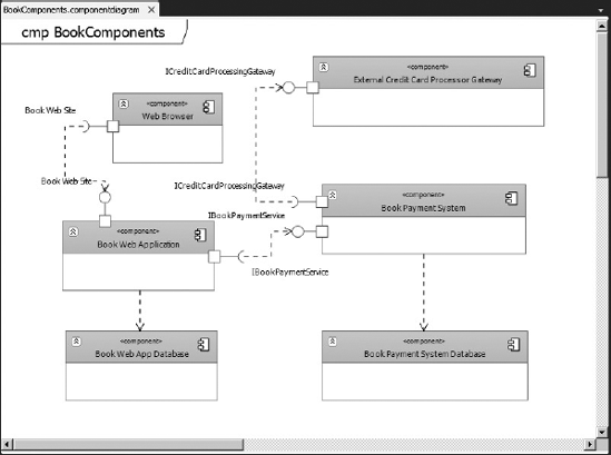
Component diagrams help visualize the high-level structure of the software system. Figure 1-5 shows an example of a component diagram.
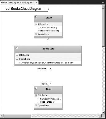
Class diagrams describe the objects in the application system. They do this without referencing any particular implementation of the system itself. Figure 1-6 shows an example of a class diagram.
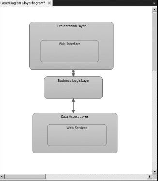
Layer diagrams are used to describe the logical architecture of your system. A layer diagram organizes the objects in your code into different groups (or layers) that describe the different tasks those objects perform. Figure 1-7 shows an example of a layer diagram.
The new Architecture Explorer tool provided by Visual Studio 2010 helps in understanding the existing architecture of a code base. This tool allows you to drill down into an existing code base, or even into compiled managed code, to help you understand how the application works, without having to open a single code file. Figure 1-8 shows an example of Architecture Explorer.
The Architecture Explorer can also lead into the world of dependency graphs, which are a new type of view in Visual Studio 2010 Ultimate that makes it easy to understand code that is new or unfamiliar. Dependency graphs make use of the Directed Graph Markup Language (DGML) to show the relationships between different areas of code in an easy-to-understand, graphical fashion.

Note
The Architecture Explorer is not the only way to create dependency graphs. Chapter 4 also shows other ways that dependency graphs can be created.
This chapter began by establishing the case for even doing design — specifically visual design — in the first place. The discussion highlighted the two main pillars that support that vision — namely, MDD and DSLs.
Because the underlying technologies have also evolved over time, thereby influencing the kinds of design you'll produce, this chapter also traced that evolution of concepts from the original object-oriented paradigm, through components and distributed-components, to the SOAs that represent the current wisdom.
This chapter concluded with a brief look at some of the new UML diagrams that are available in Visual Studio 2010, as well as the new Architecture Explorer tool.
Chapter 2 looks at how these UML diagrams are used and implemented in Visual Studio 2010 Ultimate. These diagrams are extremely useful from a modeling perspective, especially for communicating what the project is trying to accomplish, and how the different systems will interact.