3
Introduction to ESP Development Boards
In this book, we will be using two types of ESP-based development boards manufactured by Espressif Systems (688018.SH). Espressif Systems is a public multinational, fabless semiconductor company established in 2008. They mainly develop state-of-the-art Wi-Fi and Bluetooth-based IoT development boards and SoCs. Their popular products include the ESP8266 (the chipset powering the popularly known NodeMCU), ESP32, ESP32-S, and ESP32-C series of chips, modules, and development boards.
This chapter introduces you to two of the most popular development boards: the ESP8266 based NodeMCU and the ESP32 development board. The chapter is divided into 3 main sections:
- ESP8266-based NodeMCU development board
- ESP32-based development board
- Mini-Project 1: NodeMCU as an MQTT client
This chapter will be divided into three main sections. The first two sections will provide details about these development boards, discussing each point listed as follows:
- Technical specifications of the development board
- The pinout diagram and GPIO configuration
- Software setup to program these boards using the Arduino IDE
Finally, we will create our very first mini-project, where we will set up a NodeMCU development board as an MQTT client. This will connect to our Raspberry Pi MQTT broker and control its onboard LED using the terminal of our home computer. Exciting, right?
Let’s waste no more time and dive in!
ESP8266-based NodeMCU development board
NodeMCU is an open source development board that is designed to prototype IoT applications. The development board equips the ESP-12E module, which contains an ESP8266 chip. This chip has a Tensilica Xtensa® 32-bit LX106 RISC microprocessor that operates at an 80 to 160 MHz-adjustable clock frequency and supports RTOS.
The board can be programmed using two languages, as follows:
- Embedded C (using the popular Arduino IDE)
- Lua Programming Language
We will learn how to program NodeMCU through the Arduino IDE later in this chapter.
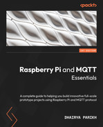
First, let’s look at the actual development board. The following is a diagram of the NodeMCU board with the important peripherals of the board labeled accordingly:
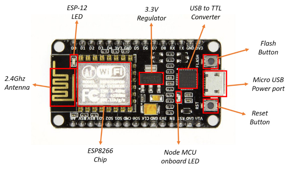
Figure 3.1 – A NodeMCU development board
Next, we will look at the technical specifications for this development board.
Technical specifications
The development kit that’s based on ESP8266 integrates GPIO, PWM, IIC, and the 1-Wire and ADC all-in-one board. You can power your development in the fastest way by combining this with NodeMCU firmware. The technical specifications for the NodeMCU development board are as follows:
- Wi-Fi Module: An ESP-12E (32-bit) module that’s similar to the ESP-12 module but with six extra GPIOs that support the 802.11 b/g/n Wi-Fi protocol.
- Power Source: A micro USB port for power, programming, and debugging.
- Headers: A 2 x 2.54 mm 15-pin header with access to GPIOs, SPI, UART, ADC, and power pins. We will discuss the GPIO pinout in detail in the next section.
- Power Rating: The required power to power the board is 2.6 to 3.3 V with a current of 250 mA. The USB port provides 5 V, which is regulated to 3.3 V by an on-chip AMS1117 voltage regulator board.
- Dimensions: 49 x 24.5 x 13 mm.
- Flash Memory: 4 MB.
- SRAM: 64 KB.
- ADC Pins: It has 1 ADC pin, which has a voltage range of 0 - 3.3 V.
- Digital Pins: It has 11 digital I/O pins.
- Miscellaneous: Reset and Flash buttons.
- Temperature Range: The company has rated the temperature range for the product to be between -40 degrees to 125 degrees Celsius.
- Price: The NodeMCU board retails in the price range of $2 to $5.
Next, we will look at the pins that the development board boasts and the configuration and functionality of each pin.
NodeMCU GPIO pinout and pin configurations
The ESP8266 NodeMCU board has a total of 30 pins that can be used to connect it to any peripherals or development boards.
The following diagram shows the GPIO pinout for the NodeMCU development board:
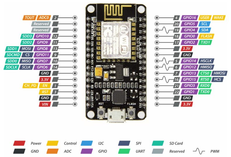
Figure 3.2 – NodeMCU detailed pinout diagram
The preceding diagram seems considerably complex. So, let’s cover it in parts to make understanding it easy. The first thing to notice is that there are several pins with more than one box. What this means is that these pins have more than one possible functionality, but we can only use one at a given moment. Such pins are called multiplexed pins. We can select our preferred mode for that pin using our code. We will see how this works practically later in this book.
Now, let’s cover the pins by using the legend provided in the preceding diagram:
- Firstly, the power pins are marked in red. As the name suggests, these pins are used to supply power to external components. There are four power pins, three of which output 3.3 V (the output of the onboard 3.3 voltage regulator), and one VIN pin, which outputs the raw input voltage when the board is powered through the on-chip micro USB port. Alternatively, it can be used to power the board through an external battery.
- There are 4 GND or ground pins on the board as well.
- The control pins are used to control the ESP8266 chip. There are three such pins of importance on the board: the Enable (EN), Reset (RST), and Wake (WAKE) pins. They have different functionalities, as follows:
- The Enable pin is used to enable or disable the ESP8266 chip. Supplying a HIGH or 3.3 V signal will enable the ESP8266 chip, while a LOW or GND signal will operate the ESP chip on minimum or low power mode.
- The Reset pin, as its name suggests, is used to reset the ESP8266 chip.
- The Wake pin helps us wake the ESP8266 chip from deep sleep (one of the low-power modes).
- The ADC pins are a part of the 10-bit ADC that the NodeMCU board possesses. The maximum voltage for this ADC is 1 V (0 to 1 V). There are two pins on the board: the ADC0 and TOUT pins.
- The UART pins provide a serial communication interface. The NodeMCU board has two such interfaces: UART0 and UART1. The maximum communication speed is 4.5 Mbps. The UART0 interface consists of TXD0, RXD0, CTS0, and RST0 pins to enable both transmission and reception of signals. On the other hand, the UART1 interface just has a TXD1 pin, so it only supports transmission capabilities. One example application for such an interface could be logging.
- The SPI pins provide an SPI communication interface. The NodeMCU board has two SPI interfaces: SPI and HSPI. There are eight SPI pins on the board, four for each interface.
- The ESP8266 features an SDIO interface as well, which can be used to directly interface SD cards. 4-bit 25 MHz SDIO v1.1 and 4-bit 50 MHz SDIO v2.0 are supported. There are six pins for this interface on the board.
- There are 17 GPIO pins on the NodeMCU board, which can be used to connect peripherals and other boards. It can be assigned various functions as the majority of these pins are multiplexed. You can pull the pin up or down internally through software commands. It can act as an input and can be set to trigger when it receives a certain signal.
- Additionally, the board supports the I2C communication interface. Both master and slave functionality is supported, with a maximum clock frequency of 100 kHz. There are two pins for this interface on the board: the SDA (data) and SCL (clock) pins.
- Finally, there are two reserved pins on the board. Additionally, some GPIO pins have a wave-like symbol beside them, which signifies that they are PWM (Pulse Width Modulation) pins. The PWM frequency range for this board is 100 Hz to 1 kHz.
This concludes this section. Now that we know a lot about the NodeMCU development board (both its hardware and its GPIO pinout), let’s learn how to set up the Arduino IDE so that we can program this board through that software. We can even set up our Raspberry Pi to program this board, but for the sake of simplicity, we will stick to the PC setup.
Arduino IDE setup for the NodeMCU development board
There are two ways to program the board: we can either use Arduino-based C programming or the Lua programming language.
We will stick to the Arduino IDE setup for this tutorial as it is easier to follow and much more reliable. Follow these steps to successfully run your first program on the NodeMCU board:
- First, go to https://www.arduino.cc/en/software and download the latest stable version of Arduino IDE for your computer. This can be seen in the following screenshot:

Figure 3.3 – Choose the download option for your computer’s OS
- Once the installer (executable file) has been downloaded, just install the IDE on your computer. To do so, just follow the onscreen steps and keep pressing the Next button.
Note
For Windows 8.1 or higher, you can just download the Arduino app from Microsoft Store. If you downloaded a ZIP file, just extract the contents, copy the extracted Arduino folder to the desired destination, and launch the application.
- Once the IDE is successfully installed on your computer, open it through the app icon or from the start or search menu, depending on the operating system you are using.
Although the development environment has been installed on your computer, it does not support the programming of ESP-based boards out of the box. We need some additional setup for that. For this, you must go to File | Preferences, as shown in the following screenshot:
Figure 3.4 – Arduino IDE – Preferences
- In the Additional Board Manager URLs area, paste the following URL:
http://arduino.esp8266.com/stable/package_esp8266com_index.json
- Now, press OK.
This will allow you to download the necessary package files for ESP8266 development from Boards Manager.
- The next step is to download all the packages and files needed by the Arduino IDE. To do that, go to Tools | Board: "Arduino Uno" | Boards Manager.
- In the search bar, search for esp8266. You will see find an option by that name, thanks to the URL we entered:

Figure 3.5 – Arduino IDE Boards Manager
- Install the esp8266 package (the latest version) by pressing the Install button. It will take around 4 to 5 minutes to download and install all the requirements.
Now, you are ready to program your ESP8266-based development boards!
Let’s verify this by uploading the LED Blink code onto our NodeMCU board:
- Open the example Blink code by going to File | Examples | 01. Basics | Blink.
This will open the LED Blink example code in a new window. The code is very simple, as shown here:
void setup ()
{
pinMode (LED_BUILTIN, OUTPUT);
}
void loop ()
{
digitalWrite (LED_BUILTIN, HIGH);
delay (1000);
digitalWrite (LED_BUILTIN, LOW);
delay (1000);
}
- Now, we need to select the Node MCU dev board from the Boards menu so that the IDE recognizes our board. To do so, go to Tools | Board: ‘x’ | ESP8266 Boards | NodeMCU 1.0.
The next step involves connecting the board and selecting the appropriate COM port. This specifies which USB port your NodeMCU board is connected to.
Important Note
If you are using an older version of the Arduino IDE, you may see a single list of boards instead of the ESP8266 Boards section. Just scroll down the list to find the board mentioned previously and click on it.
- Connect your NodeMCU board to your PC using a USB to micro USB cable. Once you’ve done this, your computer may install some drivers if you are connecting the device for the first time, but this process does not usually occur in newer systems. Make sure that any other USB devices connected to the computer are disconnected.
- Now, the COM port for this device needs to be selected. This can be done by going to Tools | Port.
You should see COMxx for a Windows PC and dev/ttyUSBx for a Linux or Mac PC. Just select the port by pressing on it.
- Finally, press the Upload button, which can be found beside the tick icon on the menu on the top right-hand side of the Arduino IDE window. This can be seen in the following screenshot:

Figure 3.6 – The Upload button
- If everything works fine, the bottom window will show that the program has been successfully uploaded onto your development board and the on-board LED will start blinking in 1-second intervals.
This completes our introduction to the NodeMCU development board. The next section will introduce you to another popular development board from Espressif, the ESP32 development board. It has several additional features, such as a greater number of ADC pins, Bluetooth support, and more compared to the NodeMCU development board (its predecessor), though it comes at a slightly raised price tag of approximately $8 to $10.
ESP32-based development board
ESP32 is often considered a successor to the NodeMCU development board. It is yet another open source board designed by Espressif specifically for prototyping mobile devices, wearable electronics, and IoT applications.
The main upgrade over the last generation chip is a hybrid Wi-Fi and Bluetooth chip, which can help you provide an additional connection protocol to your application. Note that the ESP32 dev boards have a single antenna, so only one of the two protocols can be used at a given time.
The following figure shows what the development looks like. The form factor is similar to the NodeMCU development board but with some notable differences:

Figure 3.7 – ESP32 DEVKIT V1
We will be using this particular model of the ESP32 board in this book, but the information given here will be also applicable for its other versions as they are all powered by the same chip.
An overview of the ESP32 specifications is as follows:
- The ESP32 board is a dual-core 32-bit processor.
- It has Wi-Fi and Bluetooth built-in.
- Its clock frequency is up to 240 MHz and it has a 512 kB SRAM.
- This particular board has 30 GPIO pins, with 15 in each row.
- It also has a wide variety of peripherals available, such as capacitive touch, ADCs, DACs, UART, SPI, I2C, and much more.
In the next section, we will cover the technical specifications of the board in detail.
Technical specifications
The following table shows a detailed specification chart for this device. It covers all the important features and peripherals of the ESP32 development board (ESP32 DEVKIT V1 in particular):

Table 3.1 – Technical specifications of ESP32 DEVKIT V1
Next, we will cover the pinout of the ESP32 development board in detail, as we did for the NodeMCU development board. There are some additional features that this board boasts over its predecessor in terms of GPIO pins as well.
ESP32 GPIO pinout and pin configurations
The following diagram shows that there are numerous types of pins on the board:

Figure 3.8 – ESP32 development board pinout diagram
A single pin is multiplexed so that it can perform multiple tasks. These can be decided on using its multiplexing select registers. For now, we will stick to the simple parts and provide an overview of the different pins there are:
- There are two Power pins: VIN and 3.3 V.
The VIN pin is used to provide external power to the board, while the 3.3 V pin powers the sensors connected to the board.
- There are two Ground pins on the board that can be used for multiple purposes.
- There are 15 accessible ADC pins, which are marked as ADCx_y in the preceding diagram. These pins are used to collect analog data from various sensors or other sources.
- There are 25 GPIO pins (purple-colored and multiplexed) that the user can use to connect various digital data sensors to the board. However, there are always some essential pins that will be needed for other applications, so using all 25 pins at once is very rare, but possible.
- The ESP32 board even has two Digital to Analog (DAC) converter pins.
- There are three UART channels in total, out of which one is used by the micro USB port and the remaining two can be accessed through the U0 and U2 Tx and Rx pins.
- The board also has Serial Peripheral Interface (SPI) pins, which include the MOSI, MISO, SCK, and CS pins. Moreover, it also provides I2C protocol support by using the provided SDA and SCL pins.
- Nine pins can be used to access the on-chip Touch sensor. These are marked as Touch0 to Touch9 in the preceding pinout diagram.
- There are two XTAL pins, which can be used to connect an external crystal (to provide a clock signal) to the ULP processor.
- Finally, there are the SensVP and SensVN pins, which are dedicated to measuring small DC signals (for example, from a thermocouple).
This concludes the pinout diagram description for the ESP32 board. If you wish to learn more, please check out the official documentation of the ESP32 chip, which is provided on the official Espressif site:
https://docs.espressif.com/projects/esp-idf/en/latest/esp32/
Arduino IDE setup for the ESP32 development board
When it comes to programming, the ESP32 board can easily be programmed through the Arduino IDE, which is an open source development environment for different development boards (by default, it can be only used for Arduino boards).
Fortunately, we have to follow the same process we did for the NodeMCU board, but with a few minor changes. Some additional steps need to be followed to program the ESP32 board:
- Change 1: Follow Steps 1 to 3 for the NodeMCU board as-is. In Step 4, please copy the https://raw.githubusercontent.com/espressif/arduino-esp32/gh-pages/package_esp32_index.json link instead of the one specified previously. Note that to keep both, just put a comma (,), after the ESP8266 link and type in the link mentioned previously.
Now, Boards manager knows where to look for all the necessary files that will allow us to program the ESP32 boards using the Arduino IDE.
- Change 2: When you open Boards Manager in the next step, instead of searching for esp8266, just search for esp32 and install the necessary files for them. It will take around 10 minutes to download and install all the necessary files.
- Change 3: Finally, instead of choosing the NodeMCU as the board, we must choose the ESP32 Board option.
You would most probably have an ESP32 DEVKIT V1 as it is the most popular and cheapest option of all. Choose the DOIT ESP32 DEVKIT V1 option from the ESP32 Boards section.
Now, you should be able to successfully load the Blink program onto your ESP32.
Important Note
In some ESP32 boards, the program won’t start uploading automatically once you press the Upload button in the IDE. It will keep trying to detect the board. There is a very simple fix for this issue.
Once you have pressed the Upload button, just press and hold the BOOT button on the ESP32 kit. It will automatically detect the board and start uploading.
With that, we have introduced two very useful and powerful development boards developed specifically for Internet of Things (IoT) applications.
Please note that we will be using these boards throughout this book. In fact, in the later chapters, these boards will act as the sensor nodes for our projects, so you need to become familiar with these devices.
In the next section, we will be creating our first project, wherein we will use an external development board as an MQTT client that will establish a connection to your Raspberry Pi MQTT broker. Here, we will do the following:
- Set up a NodeMCU device as an MQTT client.
- Connect this client to our Raspberry Pi MQTT broker.
- Send dummy data from the NodeMCU device to our Pi MQTT broker and control the NodeMCU’s onboard LED through MQTT.
Let’s get started.
Mini-project 1: NodeMCU as an MQTT client
This is the first project we will be doing related to MQTT and our Raspberry Pi broker.
First, we will start by setting up the NodeMCU board. No external connections need to be made as we are only controlling the on-chip LED. This will be divided into two parts:
- Node MCU setup and code explanation
- Raspberry Pi setup and project demonstration
We will first set up our NodeMCU development board for this project.
Part 1 – NodeMCU development board setup
In this section, we will program our NodeMCU board to act as an MQTT client and control its onboard LED using an external device (your home computer, in this case).
For this, we will write a sketch that gives us access to the features we need. We will be using the pubsub library for this purpose. The code we will be using will do the following:
- First, it will connect to an MQTT server.
- Once the connection has been established, it will publish "hello world" to the outTopic topic every 2 seconds.
- Once the connection has been established, it will subscribe to the inTopic/LED topic, printing out any messages it receives.
- It will receive messages from the subscribed topics and assume that the received payloads are strings, not binary. If the first character of inTopic is a 1, it will be programmed to switch the onboard ESP LED on; otherwise, it will switch it off.
- It will reconnect to the server if the connection is lost using a blocking reconnect function.
Code explanation
Now, let’s go through the code in parts so that we can understand it better:
- The first two lines of code import the required libraries. The ESP8266WiFi library is used to access Wi-Fi networks, which grants the board internet access. The PubSubClient library is the MQTT client library, which helps us run an MQTT client on the board:
#include <ESP8266WiFi.h>
#include <PubSubClient.h>
- The next three lines are constant variable initializations for the Wi-Fi name, password, and the MQTT (our Raspberry Pi’s) IP address. The Raspberry Pi’s IP address is the IP address of the broker.
The following few lines deal with various object and variable initializations that will be required later in our code:
const char* ssid = "wifi_name";
const char* password = "wifi_password";
const char* mqtt_server = "ip_of_raspberry_pi";
WiFiClient espClient;
PubSubClient client(espClient);
unsigned long lastMsg = 0;
#define MSG_BUFFER_SIZE (50)
char msg[MSG_BUFFER_SIZE];
int value = 0;
- setup_wifi is a custom function that’s used to connect to the Wi-Fi network. We provided the network’s credentials as constant variables:
void setup_wifi()
{
delay(10);
// We start by connecting to a WiFi network
Serial.println();
Serial.print("Connecting to ");
Serial.println(ssid);
WiFi.mode(WIFI_STA);
WiFi.begin(ssid, password);
while (WiFi.status() != WL_CONNECTED)
{
delay(500);
Serial.print(".");
}
randomSeed(micros());
Serial.println("");
Serial.println("WiFi connected");
Serial.println("IP address: ");
Serial.println(WiFi.localIP());
}
- The callback function is used to print out the data that’s received on the subscribed MQTT channels. In this case, we are subscribed to a topic called inTopic. We will be sending data to this to control the onboard LED. We have programmed the function so that if it receives 1 on the topic, the LED turns on, while if it receives 0 on the topic, it turns off:
void callback(char* topic, byte* payload, unsigned int length)
{
Serial.print("Message arrived [");
Serial.print(topic);
Serial.print("] ");
for (int i = 0; i < length; i++) {
Serial.print((char)payload[i]);
}
Serial.println();
// Switch on the LED if an 1 was received as first character
if ((char)payload[0] == '1')
{
digitalWrite(BUILTIN_LED, LOW);
}
else
{
digitalWrite(BUILTIN_LED, HIGH);
}
}
- The reconnect function is used to reconnect to the MQTT broker in case there is a problem and the board disconnects. We must create a random client ID so that there is no possibility of a duplicate client ID. We use the random function and create a 16-byte random hex value and append it with the ESP8266Client- string. The reasons for disconnection may include internet connection failure, duplicate client IDs, and so on.
- After that, we will be using the pub-sub client library’s connect, publish, and subscribe functions (the main MQTT functions) for specific tasks. Let’s take a look at these now.
- Connect function
First, we will attempt to establish a connection with the MQTT broker with the generated client ID using the connect function. Please note that you can have other arguments for this function as well (for instance, if you have security enabled, you will need to send the user ID and password as well).
All these parameters were discussed in detail in Chapter 2, MQTT in Detail, when we discussed the theory of MQTT in detail. Information about this function is provided in the following screenshot:
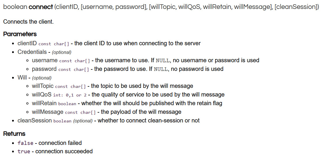
Figure 3.9 – Pub-sub client connect function explained
- Publish function
Once the connection to the broker has been established, we publish a hello world! message on the outTopic topic to acknowledge that the connection has been established. The publish function performs this task. Information about this function is provided in the following screenshot:

Figure 3.10 – Pub-sub client publish function explained
- Subscribe function
Finally, once we have the connection, we will subscribe to the inTopic/LED topic to control the onboard LED on the NodeMCU board. The function just takes the topic name as an argument for this project. However, we can also set the QoS (which was discussed in Chapter 2, MQTT in Detail, as well) value for this topic. Information about this function is provided in the following screenshot:

Figure 3.11 – Pub-sub client subscribe function explained
If you still need to dive deeper into the pub sub-client library, you can find the complete documentation for this at https://pubsubclient.knolleary.net/api#connect.
Note that this function tries to connect to the MQTT broker every 5 seconds:
void reconnect()
{
// Loop until we're reconnected
while (!client.connected()) {
Serial.print("Attempting MQTT connection...");
// Create a random client ID
String clientId = "ESP8266Client-";
clientId += String(random(0xffff), HEX);
// Attempt to connect
if (client.connect(clientId.c_str())) {
Serial.println("connected");
// Once connected, publish an announcement...
client.publish("outTopic", "hello world");
// ... and resubscribe
client.subscribe("inTopic/LED");
} else {
Serial.print("failed, rc=");
Serial.print(client.state());
Serial.println(" try again in 5 seconds");
// Wait 5 seconds before retrying
delay(5000);
}
}
}
- This is the Arduino setup function. Here, we set the built-in LED pin mode to output. Then, we initiate a serial connection with a baud rate of 115200. Next, we call the setup_wifi function to connect to the Wi-Fi network.
Next, we connect to the MQTT server, which in our case is the Raspberry Pi. Then, we specify the callback function using the setCallback function of the PubSubClient library. Finally, we subscribe to the inTopic/LED topic so that we can control the onboard LED:
void setup()
{
pinMode(BUILTIN_LED, OUTPUT);
// Initialize the BUILTIN_LED pin as an output
Serial.begin(115200);
setup_wifi();
client.setServer(mqtt_server, 1883);
client.setCallback(callback);
client.subscribe("inTopic/LED");
}
The final loop function runs indefinitely. First, we check if the MQTT client is disconnected and if so, we run the reconnect function. After that, we publish a Hello world x message every 2 seconds to the outTopic topic, where x is a variable whose value keeps incrementing.
In addition to this, we already have the callback function defined. So, if we send a 0 or 1 to inTopic, we can control the LED on the NodeMCU board:
void loop() {
if (!client.connected()) {
reconnect();
}
client.loop();
unsigned long now = millis();
if (now - lastMsg > 2000) {
lastMsg = now;
++value;
snprintf (msg, MSG_BUFFER_SIZE, "hello world #%ld", value);
Serial.print("Publish message: ");
Serial.println(msg);
client.publish("outTopic", msg);
}
}
With that, we have explained the code. You can find the complete code for this project in this book’s GitHub repository, along with comments to guide you through. Just upload this code to the NodeMCU board to complete the NodeMCU setup.
Now, let’s set up the Raspberry Pi.
Part 2 – Raspberry Pi setup
This is the easy part of this tutorial. All we need to do is to test and demonstrate that we can control the onboard LED of the NodeMCU board wirelessly through MQTT.
We will use the Raspberry Pi as an MQTT client to control the NodeMCU’s onboard LED. Follow these steps:
- Open a Terminal and start the MQTT broker on the Pi if it is not already active. It is highly unlikely that it would be inactive if you have followed the steps provided in the previous chapters.
- Now, open two new Terminal windows. We will use one of them as an MQTT subscriber that subscribes to outTopic and the other as an MQTT publisher, which will let us control the onboard LED of the NodeMCU board.
- In one Terminal window, type the following command:
mosquitto_sub -v -t outTopic
This will subscribe to outTopic, which the NodeMCU board has been sending the dummy messages to. They should start appearing on the Terminal every 2 seconds.
- In the second Terminal, type the following two commands one after the other:
mosquitto_pub -t inTopic/LED -m 1
mosquitto_pub -t inTopic/LED -m 0
The first command will turn on the NodeMCU’s onboard LED, while the second command will turn it off.
That’s all we need to do to set up the Raspberry Pi. The following screenshot shows what the final screen of the Raspberry Pi should look like. You can also see the Arduino IDE Serial Monitor output in the image, which logs all the published and received messages:
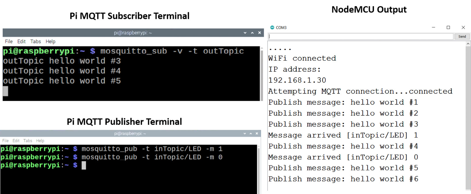
Figure 3.12 – Mini-project output demonstration – Raspberry Pi
Great! You’ve just completed your very first mini-project and controlled a peripheral of an MQTT client wirelessly using the MQTT protocol. This also marks the end of this chapter. Now, let’s summarize what we’ve learned.
Summary
This chapter was solely dedicated to the ESP development boards that we will be using throughout this book, even in the full-scale projects that we will be creating in the upcoming chapters. First, we covered the NodeMCU development board, including its technical specifications, and its GPIO configuration, before learning how to set up the Arduino IDE for this board and flashing our very first program. Next, we covered the same topics for the ESP32 development board, which is often considered a successor of the latter with some additional features. Finally, we built our very first mini-project. We turned our NodeMCU board into an MQTT client and controlled its onboard LED wirelessly using the MQTT communication protocol.
In the next chapter, we will look at another important component that will be very useful later in this book when we cover two full projects: Node-RED.
We will use this to create dashboards for our projects and learn how we can store the received MQTT data in a SQL database later in this book.