4. Checking the Actual Capabilities of Your Robot
Robot Sensitivity Training Lesson #4: Some robots underperform only because their potential has been overpromised.
Understanding the robot’s real capabilities is a prerequisite to coming up with the robot’s vocabularies, ROLL model, or any useful programming. The robot capability matrix is designed to keep track of what parts and capabilities a robot has.
Our first cut at a robot capability matrix from Table 2.1 listed the sensors, end-effectors, microcontroller, and type of robot, but that only tells part of the story. Some of the capabilities were taken directly from the manufacturers’ specifications. But a note of caution is in order. The specifications for the robot’s sensors, actuators, motors, and controllers are often one thing on paper and something different during robot use. Take, for example, a sensor’s specification. There is a certain amount of error or limit to the precision of any sensor or actuator; for example:
![]() Actual measurable distance by a sensor is less than specified measurable difference.
Actual measurable distance by a sensor is less than specified measurable difference.
![]() A light sensor is specified to recognize three colors but actually only recognizes two colors.
A light sensor is specified to recognize three colors but actually only recognizes two colors.
The error rate for a sensor may not be stated clearly or may be totally missing in the documentation. Not all motors are created equal, and there is a great deal of variance in the level of precision an actuator may support.
![]() Note
Note
Remember, the actuators/motors ultimately determine how fast a robot can move. A robot’s acceleration is tied to its actuators. The actuators are also responsible for how much a robot can lift or how much a robot can hold.
Since sensors, actuators, and end-effectors can be controlled by programming, performance levels and limitations have to be identified prior to the programming effort. Manufacturers are sometimes overly optimistic about the performance of a controller, sensor, or actuator, and the actual capability turns out to be different from the specified capability. In other instances, there are simply mistakes or typos in the documentation; for example, the documentation specifies kilograms for actuator capability when grams should have been used.
It is a waste of effort and could result in damage to the robot if instructions given to the robot rely on manufacturer specifications that were not correct. For example, actuators and motors provide most of the work required for robot arms. So instructing a robot arm to lift and relocate 2 liters when its actuators can only handle 1.8 liters could result in damage to the robot’s servos or present some kind of safety issue.
![]() Note
Note
An EEPROM, or electrically erasable programmable read-only memory, like a regular ROM chip, uses a grid and electrical impulses to create binary data. However, the difference between ROM chips and EEPROM chips is that EEPROM chips can be reprogrammed without removing them from the computer, contrary to basic ROM chips, which can only be programmed one time.
Engaging robot actuators with too much weight is a common cause of robot failure. Over specified sensors are another common cause of robot failure. Relying on a robot’s sensors in situations that call for the identification of objects of different sizes, shapes, and colors when the scanning sensor can only recognize one shape and one color is typical of the kinds of mismatches found between sensor specifications and actual sensor performance.
Before the real programming effort begins we have to check or test the components of the basic robot skeleton shown in Figure 4.1. These components are the hardware foundation of robot programming. Any one of these components can be a show-stopper, so it’s important to know the basic limits of each. The microcontroller contains the microprocessor, input/output ports, sensor ports, and various types of memory, flash RAM, and EEPROM. Figure 4.2 contains the basic layout of a microcontroller.


![]() Tip
Tip
A robot may have multiple controllers. It’s important to know the actual specifications. A robot may have one controller for motors and another controller for servos and yet another controller for communications.
The Reality Check for the Microcontroller
Some of the things we want to check on the microcontroller are:
![]() How much actual memory is available for program use? (How much is actually free?)
How much actual memory is available for program use? (How much is actually free?)
![]() Is there any flash memory or access to auxiliary storage from the microcontroller?
Is there any flash memory or access to auxiliary storage from the microcontroller?
![]() What is the data rate transfer on the microcontroller?
What is the data rate transfer on the microcontroller?
We don’t want to have a situation where the sensors are generating more data or generating it faster than what the microprocessor and memory can handle. We don’t want mismatches between sensor, motor, and microprocessor data transfer rates. Data acquisition rates versus data processing rates is an important area to consider when developing useful robot applications.
Microcontrollers typically come with some kind of utility that reports system information. The operating environment the microcontroller works in will also have some way of reporting system information. In this book, we get you started with the basics.
Accessing the information depends on the kind of robot the microcontroller is supporting. Some robots send feedback to the programmer via digital display monitor; others write the feedback to internal memory or some kind of external memory device accessible by the programmer. Let’s take a look at two commonly found low-cost robot microcontrollers: the Arduino Uno and the Mindstorms EV3.
Figure 4.3 shows a photo of the Arduino Uno microcontroller we use to control one of the Arduino-based robot arms that we use for code examples in this book.

The Arduino ShowInfo is an example of the kind of utility that can be used with a microcontroller. The ShowInfo utility can be used to get the actual specifications of the microcontroller connected to an Arduino-based robot. Type the command, followed by the Enter key. Our version of ShowInfo presents the programmer with a menu like the one shown in Listing 4.1.
Listing 4.1 Arduino ShowInfo Menu
i = Show information
h = Show menu
r = Test serial communication
s = Speed tests
t = Timer Register Dump
? = Show menu
Examples of the output for the Speed tests option are shown in Listing 4.2 and Listing 4.3.
Listing 4.2 Example Output for the Speed Tests Option of the Arduino ShowInfo Utility
F_CPU = 16000000 Hz
1/F_CPU = 0.0625 us
Listing 4.3 is an example of the output for the next tests of runtime compensated for overhead. The interrupts are still enabled because millis() is used for timing.
Listing 4.3 Example Output for the Speed Tests of Runtime Compensated for Overhead
nop : 0.063 us
avr gcc I/O : 0.125 us
Arduino digitalRead : 3.585 us
Arduino digitalWrite : 5.092 us
pinMode : 4.217 us
multiply byte : 0.632 us
divide byte : 5.412 us
add byte : 0.569 us
multiply integer : 1.387 us
divide integer : 14.277 us
add integer : 0.883 us
multiply long : 6.100 us
divide long : 38.687 us
add long : 1.763 us
multiply float : 7.110 us
divide float : 79.962 us
add float : 9.227 us
itoa() : 13.397 us
ltoa() : 126.487 us
dtostrf() : 78.962 us
random() : 51.512 us
y |= (1<<x) : 0.569 us
bitSet() : 0.569 us
analogRead() : 111.987 us
analogWrite() PWM : 11.732 us
delay(1) : 1006.987 us
delay(100) : 99999.984 us
delayMicroseconds(2) : 0.506 us
delayMicroseconds(5) : 3.587 us
delayMicroseconds(100) : 99.087 us
The ShowInfo utility works for Arduino-based microcontrollers. Most microcontrollers come with their own version of a “show info” utility. For microcontrollers that have embedded Linux, there are additional options to find out information. For example, Mindstorms EV3 and WowWee’s RS Media microcontrollers have embedded Linux and information on the processor, and opening proc/info can reveal some information about the processor. For example, the command:
more /proc/cpuinfo
on our EV3 microcontroller produces the output in Listing 4.4.
Listing 4.4 Example Output of more /proc/cpuinfo Command on the EV3 Microcontroller
Processor : ARM926EJ-S rev 5 (v5l)
BogoMIPS : 1495.04
Features : swp half thumb fastmult edsp java
CPU implementer : 0x41
CPU architecture: 5TEJ
CPU variant : 0x0
CPU part : 0x926
CPU revision : 5
Hardware : MindStorms EV3
Revision : 0000
Serial : 0000000000000000
Executing the command uname on our EV3:
uname -a
LINUX EV3 2.6.33-rc4 #5 PREEMPT CET 2014 armv5tejl unknown
gives us the version of LINUX and processor for our EV3.
Running the free command on the EV3 controller gives us the output in Listing 4.5.
Listing 4.5 Example Output for Running free Command on EV3 Controller
root@EV3:~# free
total used free shared buffers
Mem: 60860 58520 2340 0 1468
Swap: 0 0 0
Total: 60860 58520 2340
These values give you some identifying information for components of the microcontroller, such as:
![]() Processor type
Processor type
![]() Processor speed
Processor speed
![]() Memory capacity
Memory capacity
![]() Memory free
Memory free
![]() Memory in use
Memory in use
It’s a good idea to compare information found running the microcontroller utilities or looking at /proc/cpuinfo and /proc/meminfo with the specification or data sheet that comes with the microcontroller and note any major discrepancies. Free memory limits the size of a program that can be loaded into the robot or the amount of sensor or communication data that can be handled in real-time by the robot.
Whereas the processor speed will limit how fast instructions can be executed by the robot and the data transfer rate between the processor and the ports, the available free memory has a major impact on how fast and how much sensor data can be processed. Keep in mind that the processor controls the flow of data and signals for the robot. So questions like:
![]() How much data can the robot handle?
How much data can the robot handle?
![]() What’s the largest chunk of data the robot can handle at one time?
What’s the largest chunk of data the robot can handle at one time?
![]() How many signals can the robot send or receive simultaneously?
How many signals can the robot send or receive simultaneously?
![]() How fast can the robot process signals or data?
How fast can the robot process signals or data?
are all answered by the microcontroller’s actual capability. The ATmega, ARM7, and ARM9 family of microcontrollers are the most popular and perhaps the most commonly found low-cost microcontrollers used for mobile and autonomous robots. All robots used for examples in this book use one or more of these microcontrollers.
Sensor Reality Check
Infrared sensors, ultrasonic sensors, light sensors, color sensors, heat sensors, and chemical sensors all sound like really cool sensors to have for a robot—and they are. But the devil is in the details. All sensors have some baseline capability, limit to their precision, and some amount of error relative to that baseline capability. All sensors have constraints on how much data they can gather, how fast they can gather it, and how precisely they can measure the data.
Ultrasonic sensors work by bouncing sound off objects and measuring the time it takes to receive the signal back, thus relating distance to time. But ultrasonic sensors differ in terms of how far they can actually measure distance, how accurately they can measure time, or how consistently they can measure time or distance.
Color sensors are a nice thing to have for a robot. Color can be used as a means of programming a robot when to take various actions and what actions to take. For example, if an object is blue, instruct the robot to do action A; if the object is red, do action B, wait until the blue object turns purple, and so on.
Let’s say our robot has a color sensor that can distinguish between red, green, and blue. The issue is how accurate is the sensor. Which red does the sensor recognize? All shades of red? Can the sensor report the difference between various shades of blue—navy blue, sky blue, teal? Exactly how precise is the color sensor in distinguishing hues? If our robot is a bomb disposal robot and we instruct it to cut the orange wire and not the red wire, will there be a problem? Sensors measure things. Robots use sensors to measure things. The accuracy and limitations of the robot’s sensors have to be considered when selecting a task for the robot to perform. Many sensors have to be calibrated on the first use. Some sensors have to be calibrated after each use. The calibration process is also an important part of considering what capability or limits a robot’s sensors actually have.
Bron’s Believe Or Not
![]() Drive and get out of a car
Drive and get out of a car
![]() Open a door and walk through the doorway
Open a door and walk through the doorway
![]() Cut through a wall
Cut through a wall
![]() Turn a valve
Turn a valve
![]() Perform a surprise task
Perform a surprise task
![]() Walk through a debris field
Walk through a debris field
![]() Walk on uneven terrain
Walk on uneven terrain
![]() Climb stairs
Climb stairs

Figure 4.4 The three 2015 Darpa Robotics Challenge Finalists with some brief information about each robot
Determine Your Robot’s Sensor Limitations
Light visible to the human eye has a wavelength between 400 nm and 700 nm (see Figure 4.5). Wavelength is measured in nanometer, a unit of length in the metric system, equal to one billionth of a meter (0.000000001 m). Light that has a wavelength > 700 nm we call infrared. Light that has a wavelength < 400 nm we call ultraviolet. When a robot has an RGB (Red Green Blue) color sensor, that sensor measures lightwaves between 400 nm and 700 nm in length. For the human eye, every wavelength in that range is associated with a color.

The question is how precise and consistent is the resolution of a robot’s color sensor? Does the sensor report that every wavelength light between 400 nm and 510 nm is blue without being able to distinguish between the different blues? Does it report that every wavelength between 570 nm and 700 nm is red and make no distinction between red and light red? How can we have 4-color RGB sensors and 16-color RGB sensors? What does that mean?
In Chapter 5, “A Close Look at Sensors,” we look at how light and color sensors work and how robots use them to measure things, make decisions, and take action. Light sensors and color sensors aren’t the only sensors that have these kinds of resolution questions.
Figure 4.6 shows how loudness, softness, low tones, and high tones of sound are measured. Some robots respond to loud sounds or soft sounds or to certain tones or kinds of sound.

Sound can be used as input to the robot’s program. For example, if a sound is loud enough it causes the robot to take one action, and if the sound produces a certain tone it causes the robot to take some other action. The amplitude of the sound wavelength determines how loud or soft a sound is.
The frequency of the sound wavelength determines what tone the sound makes. So like the light sensor, a sound sensor measures wavelengths. Instead of light wavelengths, sound sensors measure sound wavelengths. The question is how loud is loud? Will the robot’s sound sensor detect every sound above 50 dB (decibels) as loud and every sound below 50 dB as soft? Can the robot’s sound sensor distinguish between 100 dB and 120 dB? It’s not only sensor measurements of light and sound wavelengths that have these resolution questions.
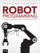
Because most sensors measure analog values there will be questions of resolution. For instance, the acidity of a liquid is determined by a chemical sensor that measures the amount of hydronium ion present. Table 4.1 shows the pH scale.
If our robot has a sensor that measures pH, would it be capable of distinguishing the difference between battery acid and lemon juice? Or would it report them both as an acid?
In our Robot Boot Camp Scenario #1, Midamba could use a robot to measure the difference between acid and bases to help him solve his battery problem. How much resolution does the robot’s pH sensor need? The limits and resolution of all the robot’s sensors should be identified and noted prior to picking situations, scenarios, and roles for the robot. The sensors roughly impact 25% of the robot’s success in executing its tasks for assigned situations and scenarios.
Actuators End-Effectors Reality Check
A robotic arm is useful in placing, lifting, and positioning objects. But all robot arms have limits to how much weight or mass they can lift or hold, or how much torque can be generated by the servos on the arm. Not all robot arms are created equal, and not all robot arms can manipulate their maximum weight objects in all positions (even positions claimed by the specifications). Figure 4.7 shows a robot’s arms with 2 and 6 DOF (Degrees of Freedom).

![]() Note
Note
Robot arm capability is often described as DOF (Degrees of Freedom). Simply put: How many modes or axes of movement can the robot arm be maneuvered in 3D space?
Some code for the robot arm examples that we use in this book was executed on the Arduino-based PhantomX Pincher robot arm manufactured by Trossen Robotics. Table 4.2 lists the manufacturer’s specifications for the arm.

These are the kinds of specifications that need to be checked for robot arms. Sometimes the manufacturer’s specifications are conservative and a component may have a little better performance than specified. For example, in this case our gripper strength was somewhat greater than 500 g, and rotating strength was a little more than 150 g. This is an important specification to note. The robot arm may be capable of holding 500 g but is not capable of rotating 500 g This fact will have an impact on how the robot arm is programmed and what it can and cannot do.
Figure 4.8 is a photo of the PhantomX Pincher robot arm used for the examples in this book.

The robot capability matrix is a good place to record the actual capabilities. We use a spreadsheet to record our capability matrix. Table 4.3 is a sample of our actual robot capability matrix in a spreadsheet.

![]() Note
Note
Although we could put multiple robots on one spreadsheet, we keep it to one spreadsheet per robot, with all sensors, actuators, and end-effector capabilities for each robot recorded on separate spreadsheets. This keeps it easy when programming, and when looking up robot capabilities.
REQUIRE Robot Effectiveness
Recall from Chapter 1, “What Is a Robot Anyway?,” we rated a robot’s effectiveness in four areas:
![]() Sensor effectiveness
Sensor effectiveness
![]() Actuator effectiveness
Actuator effectiveness
![]() End-effector effectiveness
End-effector effectiveness
![]() Controller effectiveness
Controller effectiveness
![]() Note
Note
REQUIRE stands for Robot Effectiveness Quotient Used in Real Environments. We use REQUIRE as an initial litmus test in determining what we can program a robot to do and what we won’t be able to program that robot to do.
Each area is limited by the actual capabilities of the hardware specifications. According to our Robot Effectiveness Quotient, the sensors make up 25% of the robot’s effectiveness. The robot uses sensors to measure things and then take actions and make decisions based on those measurements. Table 4.4 shows some of the common kinds of quantities that robots use sensors to measure.

The quality, accuracy, precision, resolution, and limitations of the sensors should be determined prior to programming. For example, if a robot’s sensor measures distance (length), then it has a maximum distance and a minimum distance that can be measured in terms of meters, centimeters, and so on. The ultrasonic sensors our robots use for the examples in this book have a maximum range of 100 cm and a minimum range of 10 cm. Objects outside that range cannot be detected by our robot’s distance sensors. We include the notation for basic units and symbols in Table 4.4 because you need to be able to compare apples with apples when determining a sensor’s limitation and precision.
Different sensor manufacturers specify sensor capability using different units of measure. It’s a good idea to pick one standard of measurement and stick with it when programming robots. Numbers get thrown around a lot in a typical robot application. If the units of measure are mixed, then the program will be difficult to change, maintain, and reuse. For example, let’s say our robot has both an infrared sensor and an ultrasonic sensor to measure distance simultaneously of two objects, and we want to know how far the objects are apart at any given time. We might have some robot code like the following:
Begin
Object1Distance = Robot.ultrasonicSensorGetDistance();
Object2Distance = Robot.infraRedSensorGetDistance();
...
DistanceApart = Object2Distance - Object1Distance;
Robot.report(DistanceApart).
end
What does DistanceApart represent if the ultrasonic sensor uses inches and the infrared sensor uses centimeters? Sensors from different manufacturers may be on the same robot with Manufacturer #1 using yards for distance and Manufacturer #2 using meters to describe distance. Although it is not impossible to keep track of which is which, combining different units of measure complicates matters. Also, it is difficult to use the same program between different robots if the units of measure are not consistent between robots and libraries.
It is difficult to mix and match robot program libraries if each library uses a different standard of unit measurement. When instructing the robot to measure things, you should use the same standard of unit measurement for all instructions and objects that the robot interacts with. You should use the same unit of measurement standard for all robot instruction libraries. The robot capability matrix should include a sensor capability matrix with limits specified using the applicable standard unit of measurement. We clarify this idea as we explain how to develop ROLL models for your robots in Chapter 8, “Getting Started with Autonomy: Building Your Robot’s Softbot Couterpart.” In this book, we use SI (International System of Units) units when specifying the measurement of all quantities.
What’s Ahead?
In Chapter 5, “A Close Look at Sensors,” we discuss the different types of sensors and how they work for your robot. We discuss their capabilities and limitations.