Illustrator is a program that seems to have an identity crisis. By that, I mean it’s a tool that can do many of the things that InDesign can (such as page layout), and it can also do many of the things that Photoshop can (such as web design). Of course, there are also plenty of things that Illustrator alone can do (such as edit PDF files or create 3D graphics). As you’ll see in this chapter, one thing is certain: Illustrator is a very deep program, with a wide range of features and uses.
When you first launch Illustrator, you’re greeted with the Illustrator CS3 welcome screen (see Figure 7.1). The welcome screen is split into four sections. The top two areas offer quick links to open recent files and access common functions, such as creating a new file. The bottom portion of the window provides links to How-to documents and online resources. If you’d prefer to avoid this screen altogether, you can do so by clicking the “Don’t Show Again” check box.

Taking a look at the screen when you first start Illustrator (see Figure 7.2), you have the standard menu bar across the top of the screen and, directly beneath it, Illustrator’s context-sensitive Control panel. Along the left side of the screen is the toolbox, which contains all of Illustrator’s tools, as well as several other functions. The color proxy indicates the fill and stroke colors (you can also choose colors by double-clicking on them); the two icons above the proxy enable you to set the colors to the default white fill and black stroke, and to swap the fill and stroke colors. Directly below the proxy icons are three buttons that can be used to quickly apply three kinds of colors: a white fill, a black-to-white gradient, and none. Under those are the different view modes, Standard, Full Screen with Menu Bar, and Full Screen (just as in Photoshop). You can toggle through the view modes by repeatedly pressing the F key on your keyboard (the letter F, not the Function key).

Along the right side of your screen are some of Illustrator’s panels. We discuss what each of them does and how to use them as we go through this chapter.
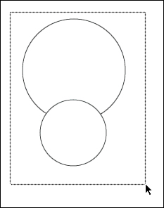
Finally, the document window is where you work on your file. The black outline is your document size, or artboard. Illustrator lists the filename, the view percentage, and the color mode right in the title bar of each file. Along the bottom left of the window, you’ll find a zoom indicator as well as the status bar.
Illustrator’s Control panel has several cool features built into it that make it extremely powerful and easy to use (see Figure 7.3). On the left of the Control panel, Illustrator indicates the targeted selection (in this case, a path). You’ll also notice that some of the words in the panel are underlined and are colored blue, just like links in a web browser. When you click on these words, Illustrator opens the panel for that feature, giving you access to all of the necessary functions. For example, you can easily specify the width for a stroke in the Control panel, but you can also click on the word Stroke to open the Stroke panel and specify additional settings. At the far right of the Control panel is the Go to Bridge button and a flyout menu that enables to you show or hide different functions in the Control panel itself.
In a program such as Photoshop, you usually start with a scanned image or a digital photograph. With Illustrator, though, you’ll most likely be creating new documents more often, as well as creating new documents based on predefined templates. Of course, Illustrator can also open existing documents.
To start from scratch and create a new file, choose File, New, or press (Cmd-N) [Ctrl+N] to access the New Document dialog box (see Figure 7.4). Here you can give your file a name (you can do this later when you actually save the file, too), choose a profile for your document, and specify your artboard size and orientation. You can choose from any of Illustrator’s supported measurement systems: points, picas, inches, millimeters, centimeters, or pixels. Using the Templates button, you can jump to a directory containing dozens of templates ranging from event planning to DVD labels to give you a jumpstart on your document design.

For even greater control, click the Advanced button to choose a preview mode, color mode, and the PPI in which raster effects will be rendered.
Illustrator lets you create files in one of two color modes, and it’s important to know which one to choose. Although you can change color modes later, such changes will cause color shifts. Each color mode has a gamut, or range of colors that can be produced. Some gamuts are wider, or can contain more colors, than others. For example, certain colors can be displayed in RGB that simply can’t be reproduced in CMYK (for example, bright greens, oranges, or pastel colors). So converting an RGB file to CMYK might cause some colors to become dull or change the colors altogether because those colors don’t exist in CMYK. Let’s take a look at each of the supported color models:
RGB Color—. RGB (red, green, blue) is a color method used to display color on televisions, computer monitors, and video screens. In RGB, you start with black (when your TV is off, the screen is black), and adding equal values of red, green, and blue results in white. When you’re working on files that will be used in video, for broadcast, on the Web, or for onscreen presentations, RGB is the format you should use.
CMYK Color—. CMYK is a color method used to print color on paper. Unlike RGB, in the CMYK color space, if you mix all the colors together, you get black, but if none of the colors is present, you get white. Anything you see in print uses CMYK (a blank piece of paper is white), so obviously, when you’re designing content that will be printed in color, CMYK is the color model of choice. CMYK stands for cyan (a shade of blue), magenta (a shade of red), yellow, and key (black).
After you’ve specified your new document settings, you can click the OK button to create a new Illustrator file.
An Illustrator template file is a special kind of Illustrator file, sporting an .ait file extension instead of the usual .ai reserved for Illustrator files. Templates are used for designs that are used repeatedly, and they can contain anything a normal Illustrator file can contain, including layers, paragraph styles, symbols, page size—even artwork itself. When you open an Illustrator template, the file opens a copy of the template as an untitled document (as if you had created a new file). This prevents you from accidentally overwriting the template file.
Illustrator ships with many professionally designed royalty-free templates you can use. When you choose File, New from Template, or click the Templates button in the New dialog, Illustrator automatically navigates to the folder where these templates are installed. Using the Adobe file dialog, you can choose Thumbnails from the View pop-up menu at the far right of the window. This automatically shows a preview of each template file as you browse, as seen in Figure 7.5. You can also use Bridge to browse through the templates if you prefer its interface.

For those who feel that using prerendered content is beneath them, Illustrator also ships with a full collection of blank templates. These can be quite useful for nearly any user.
As with just about any computer program, you can open a file by choosing File, Open or pressing (Cmd-O) [Ctrl+O] to open a file. By default, this invokes the Adobe File dialog box which features file content previews and direct access to Version Cue. If you’re more comfortable with your default operating system dialog, click the OS Dialog button. After you’ve located the file you want to open, click on the Open button to open the file. Keep in mind that you can always use Adobe Bridge to browse for the right file you need.
Illustrator does more than just open Illustrator files. You can open a wide range of files in Illustrator, including PDF, EPS, JPEG, PSD, GIF, PNG, and more. Illustrator can also open native CorelDRAW and FreeHand files (versions 8, 9, and 10 officially, although other versions might work with varying success). In many ways, both Photoshop and Illustrator can be used as utilities to open just about any kind of graphics file.
Did you Know?
If you need to edit PDF files, you can open them in Illustrator, but you’ll have to remember a few limitations. Illustrator can open only one page of a PDF file at a time (as seen in Figure 7.6), form data might be removed, and structured text (tagged text) will be lost.

Back in Chapter 2, “So Many Applications: Which One to Use?” we discussed the underlying basics of vector graphics. Now you’ll learn how to draw them. We begin with drawing closed paths, and then we move on to drawing open paths. Finally, we discuss how to edit existing vector paths and objects.
Illustrator can draw primitive shapes quite easily, and several shape tools enable you to create rectangles, ellipses (circles and ovals), polygons (multisided shapes), and stars. We go through each of these tools and how they are used, but, of course, the best way to get to know them is to launch Illustrator and try them for yourself.
One thing you’ll notice, though, as you read through the remainder of this chapter, is that there are usually several ways to accomplish the same task. This is true for most of the functionality you’ll find in Illustrator and throughout the CS3 suite. As you become more familiar with Illustrator, you’ll get a better feel for which method makes the most sense for a specific purpose or is best suited to your personal workflow.
Finally, as you’ll see, most of Illustrator’s shape drawing tools, shown in Figure 7.7, are dynamic, in that you can press certain keys on your keyboard to change certain aspects of the shape as you are drawing it.
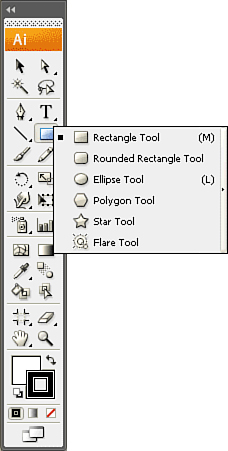
To draw a rectangle, choose the Rectangle tool and click and drag the mouse on the artboard. Before you release the mouse, you can utilize any of the following functions that will affect the shape you are drawing:
Press the Shift key to constrain your shape to be a perfect square.
Press the (Option) [Alt] key to draw your shape from the center outward.
Press the spacebar to “freeze” your shape and position it elsewhere on your artboard.
Press the tilde (~) key to create numerous copies of your shape.
To draw a rectangle numerically, choose the Rectangle tool and click once on your artboard to get the Rectangle dialog box (see Figure 7.8). Enter a value for the width and height, and click OK. To draw a rectangle numerically from its center, press and hold the (Option) [Alt] key while you click once on the artboard.

To draw a rounded rectangle (in which the corners of the rectangle are rounded), choose the Rounded Rectangle tool and click and drag the mouse on the artboard. Before you release the mouse, you can utilize any of the following functions that will affect the shape you are drawing:
Press the Shift key to constrain your shape to be a perfect square with rounded corners.
Press the (Option) [Alt] key to draw your shape from the center outward.
Press the spacebar to “freeze” your shape and position it elsewhere on your artboard.
Press the tilde (~) key to create numerous copies of your shape.
To draw a rounded rectangle numerically, choose the Rounded Rectangle tool and click once on your artboard to get the Rounded Rectangle dialog box (see Figure 7.9). Enter a value for the width, height, and corner radius, and click OK. To draw a rounded rectangle numerically from its center, press and hold the (Option) [Alt] key while you click once on the artboard.

To draw an ellipse (also called an oval), choose the Ellipse tool and click and drag the mouse on the artboard. Before you release the mouse, you can utilize any of the following functions that will affect the shape you are drawing:
Press the Shift key to constrain your shape to be a perfect circle.
Press the (Option) [Alt] key to draw your shape from the center outward.
Press the spacebar to “freeze” your shape and position it elsewhere on your artboard.
Press the tilde (~) key to create numerous copies of your shape.
To draw an ellipse numerically, choose the Ellipse tool and click once on your artboard to get the Ellipse dialog box (see Figure 7.10). Enter a value for the width and height, and click OK. To draw an ellipse numerically from its center, press and hold the (Option) [Alt] key while you click once on the artboard.

The Polygon tool in Illustrator is a bit disconcerting. A real polygon is simply a closed shape with at least three sides. In Illustrator, the Polygon tool can create only closed shapes with three or more sides, but in which all the sides are equal in length.
To draw a polygon, choose the Polygon tool, and click and drag the mouse on the artboard. A polygon is always drawn outward from its center. Before you release the mouse, you can utilize any of the following functions that will affect the shape you are drawing:
Move your mouse in a circular motion to rotate the shape.
Press the Shift key to constrain your shape straight to the baseline (or whatever your constrain angle is set to in General Preferences).
Press the up arrow key on your keyboard to add sides to your shape.
Press the down arrow key on your keyboard to remove sides from your shape.
Press the spacebar to “freeze” your shape and position it elsewhere on your artboard.
Press the tilde (~) key to create numerous copies of your shape.
To draw a polygon numerically, choose the Polygon tool and click once on your artboard to get the Polygon dialog box (see Figure 7.11). Enter a value for the radius and the number of sides, and click OK.

The Star tool in Illustrator can be quite useful for creating starbursts to call out specific items in a design.
To draw a star, choose the Star tool and click and drag the mouse on your artboard. A star is always drawn out from its center. Before you release the mouse, you can utilize any of the following functions that will affect the shape you are drawing:
Move your mouse in a circular motion to rotate the shape.
Press the Shift key to constrain your shape straight to the baseline (or whatever your constrain angle is set to in General Preferences).
Press the up arrow key on your keyboard to add points to your shape.
Press the down arrow key on your keyboard to remove points from your shape.
Press the (Option) [Alt] key to align the shoulders of your star (forcing lines on opposite sides of the star to share the same baseline).
Press the (Cmd) [Ctrl] key to adjust the inner radius of the star. Dragging toward the center of the star decreases the radius, and dragging away from the center of the star increases it.
Press the spacebar to “freeze” your shape and position it elsewhere on your artboard.
Press the tilde (~) key to create numerous copies of your shape.
To draw a star numerically, choose the Star tool and click once on your artboard to get the Star dialog box (see Figure 7.12). Enter a value for Radius 1 and Radius 2, enter the number of points, and click OK.

Illustrator CS3 introduces the Flare tool. Unlike the other shapes we’ve looked at, flares are a bit more complex. The Flare tool is used to generate the lens flare effect—a series of concentric circles, rays, and staggered halos, similar to what you might see when light shines through a lens. To get the best effect from the Flare tool, you should use it on top of existing artwork, much as you’d see one in a photograph.
To draw a flare, choose the Flare tool, and then click and drag the mouse to set a size. The main flare shape will be drawn. Next, move the mouse and click and drag to set the secondary halos for the flare. You can use the mouse to adjust their location in relation to the primary shape. Before you release the mouse, you can utilize any of the following functions that will affect the shape you are drawing:
Press the Shift key to constrain the angle of the rays in the flare straight to the baseline (or whatever your constrain angle is set to in General Preferences).
Press the up arrow key on your keyboard to add rays to your flare.
Press the down arrow key on your keyboard to remove rays from your flare.
Press the (Cmd) [Ctrl] key to keep the center of the flare from moving as you draw.
Press the tilde (~) key to create numerous copies of your shape.
To draw a flare numerically, choose the Flare tool and click once on your artboard to get the Flare Tool Options dialog box (see Figure 7.13). Enter values for the center, rings, halo, and rays, and click OK.

Although drawing complete shapes is something just about everyone needs to do inside of Illustrator, it’s equally important to create open-ended paths. Illustrator has several tools for creating these kinds of paths (seen in Figure 7.14) and, as you’ll see, different ways to edit them as well.

To draw a straight line, choose the Line Segment tool and click and drag the mouse on the artboard. Before you release the mouse, you can utilize any of the following functions that will affect the path you are drawing:
Press the Shift key to constrain your path to increments of
 .
.Press the spacebar to “freeze” your path and position it elsewhere on your artboard.
Press the tilde (~) key to create numerous copies of your path.
To draw a line numerically, choose the Line tool and click once on your artboard to get the Line Segment Tool Options dialog box, shown in Figure 7.15. Enter a value for the length and the angle, and click OK.

To draw an arc, choose the Arc tool and click and drag the mouse on the artboard. Before you release the mouse, you can utilize any of the following functions that will affect the path you are drawing:
Press the Shift key to constrain your path so that the length of the x- and y-axes are the same (thus creating a perfect quarter-circle).
Press the (Option) [Alt] key to draw your path from the center outward.
Press the up arrow key on your keyboard to make the slope of the path more convex.
Press the down arrow key on your keyboard to make the slope of the path more concave.
Press the C key to draw the arc as a closed-path shape.
Press the F key to flip the path along its axis.
Press the spacebar to “freeze” your path and position it elsewhere on your artboard.
Press the tilde (~) key to create numerous copies of your path.
To draw an arc numerically, choose the Arc tool and click once on your artboard to get the Arc Segment Tool Options dialog box (see Figure 7.16). Enter values for the length of the x-axis and the y-axis, and for the slope. Choose also to draw an open or closed path and an axis on which to base the path, and click OK.

Illustrator has a cool tool for drawing spirals, and the best part is that you don’t get dizzy drawing them!
To draw a spiral, choose the Spiral tool and click and drag the mouse on the artboard. A spiral is always drawn outward from its center. Before you release the mouse, you can utilize any of the following functions that will affect the path you are drawing:
Move your mouse in a circular motion to rotate the path.
Press the Shift key to constrain the path to increments of
.Press the up arrow key on your keyboard to add segments (or winds) to your path.
Press the down arrow key on your keyboard to remove segments (or winds) from your path.
Press the (Option) [Alt] key to adjust the length of the path.
Press the (Cmd) [Ctrl] key to adjust the decay of the path. The decay setting controls how close the winds of the spiral are to each other.
Press the spacebar to “freeze” your path and position it elsewhere on your artboard.
Press the tilde (~) key to create numerous copies of your path.
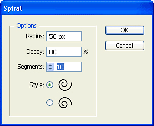
To draw a spiral numerically, choose the Spiral tool and click once on your artboard to get the Spiral dialog box (see Figure 7.17). Enter values for the radius, the decay, and the number of segments; then choose a style and click OK.
Although it’s not necessarily a path tool, the Rectangular Grid tool enables you to easily construct a grid using both paths and a single rectangle.
To draw a rectangular grid, choose the Rectangular Grid tool and click and drag the mouse on the artboard. Before you release the mouse, you can utilize any of the following functions that will affect the grid you are drawing:
Press the Shift key to constrain your grid to a perfect square.
Press the (Option) [Alt] key to draw your grid out from its center.
Press the up arrow key on your keyboard to add rows to your grid.
Press the down arrow key on your keyboard to remove rows from your grid.
Press the right arrow key on your keyboard to add columns to your grid.
Press the left arrow key on your keyboard to remove columns from your grid.
Press the X and C keys to skew your columns to the left and right.
Press the V and F keys to skew your rows to the top and bottom.
Press the spacebar to “freeze” your grid and position it elsewhere on your artboard.
Press the tilde (~) key to create numerous copies of your grid.
To draw a rectangular grid numerically, choose the Rectangular Grid tool and click once on your artboard to get the Rectangular Grid Tool Options dialog box (see Figure 7.18). Enter the appropriate values and click OK.

Similar to the Rectangular Grid tool, the Polar Grid tool creates grids that are circular in form.
To draw a polar grid, choose the Polar Grid tool, and click and drag the mouse on the artboard. Before you release the mouse, you can utilize any of the following functions that will affect the grid you are drawing:
Press the Shift key to constrain your grid to a perfect circle.
Press the (Option) [Alt] key to draw your grid out from its center.
Press the up arrow key on your keyboard to add concentric dividers to your grid.
Press the down arrow key on your keyboard to remove concentric dividers from your grid.
Press the right arrow key on your keyboard to add radial dividers to your grid.
Press the left arrow key on your keyboard to remove radial dividers from your grid.
Press the X and C keys to skew your concentric dividers closer to or farther from the center.
Press the V and F keys to skew your radial dividers to the left and right.
Press the spacebar to “freeze” your grid and position it elsewhere on your artboard.
Press the tilde (~) key to create numerous copies of your grid.
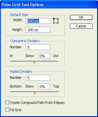
To draw a polar grid numerically, choose the Polar Grid tool and click once on your artboard to get the Polar Grid Tool Options dialog box (see Figure 7.19). Enter the appropriate values and click OK.
For drawing freestyle on your artboard, use the Pencil tool. This tool can be especially useful for sketching if you have a tablet. If you hold down the (Option) [Alt] key as you draw, Illustrator closes the path for you when you release the mouse.
There are several settings for the Pencil tool, which you can access by double-clicking on the Pencil tool itself in the toolbox. The Pencil Tool Preferences dialog box (see Figure 7.20) enables you to edit the Fidelity and Smoothness settings, which affect how clean and smooth your drawn lines will be. The Keep Selected option keeps the last path you’ve drawn with the Pencil tool selected, and the Edit Selected Paths option enables you to simply draw over an existing path to adjust it. Finally, the Fill New Pencil Strokes applies a fill to your pencil strokes after you draw them.

One of the most common tools you’ll use in Illustrator is a Bézier path. Let’s learn what these paths look like and how they work inside Illustrator.
The first type of Bézier path is a straight line; it contains two anchor points with a straight line connecting them (see Figure 7.21). This type is the simplest Bézier path and requires the least amount of memory to store and print—you just need the coordinates of the first and second points.

The second type of Bézier path is the curve, and here the description gets complicated. A curve consists of two anchor points, with a curved line connecting them. The curve is determined by control handles, which are attached to each anchor point. The control handles define exactly how the curved line is drawn between the two anchor points (see Figure 7.22).
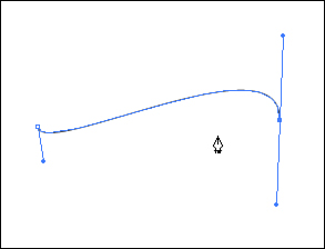
Of course, when the paths print, you don’t see the anchor points or the handles. They just appear onscreen so you can edit the paths.
Until now, you’ve been creating Bézier paths without even knowing it. The shapes and paths you’ve created are all made up of Bézier paths. You were doing fine until now, so why bring up all of this complicated anchor-point and control-handle information? The answer is, sure, you could perform several tasks in Illustrator without knowing what Bézier paths are, but you lose out on all the power that Illustrator offers. Additionally, both Photoshop and InDesign have the Pen tool and enable you to draw and edit Bézier paths.
Illustrator has three kinds of anchor points: the straight corner point, the smooth point, and the combination point. Each kind of anchor point has its specific attributes, and each is used to create different types of paths. A Bézier object can be made up of any of the three kinds of anchor points and can contain any combination of them as well. For example, a square is made up of four straight-corner anchor points, whereas a circle is made up of four smooth anchor points. A shape such as a pie wedge contains both straight-corner and combination anchor points.
The straight corner is the simplest form of the anchor point, and it is primarily used to connect straight lines (see Figure 7.23). To draw straight lines, press P to switch to the Pen tool and click once on your screen to define the first point in your line. Now click where you want the second point to appear (don’t drag from the first point—just click and release). Each time you click in a different place, Illustrator draws a line connecting the anchor points. To create a closed shape, click on the first anchor point (the Pen tool icon appears with a little O next to it when you’re about to close a path).

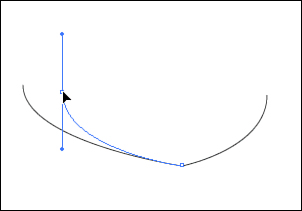
The smooth anchor point contains two control handles (see Figure 7.24). By adjusting the control handles, you determine the slope and sharpness of the curve on either side of the point. Because the path continues through the point without a sharp change in direction, it is called a smooth anchor point.

To draw curved lines, click and drag the mouse with the Pen tool to create your first point. Notice that as you drag, you’re pulling control handles out from the point. Release the mouse button and then click and drag again at a different place on your artboard. As you drag, you’ll see control handles being created for the second point, and a curved line will appear between the two points.
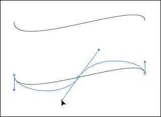
The combination anchor point is a combination of the straight anchor point and the smooth anchor point (see Figure 7.25), so using these types of points can get a bit confusing. To draw a path using a combination point, click and drag with the Pen tool to create a smooth point. Then just click elsewhere on the screen to create a corner point. Then click and drag again elsewhere to create yet another smooth point.

You’ll notice that the point in the middle has no control handles, yet it has curved paths connected to it. In reality, the combination point has two sides to it: a straight side (from the single click) and a curved side (from the click and drag).
After you draw a path, you might want to change the shape or style of the points, adjusting the curve of the path or making a corner point into a smooth point. Several tools enable you to modify a path by changing, adding, or deleting a point.
Perhaps the simplest method of editing a path is to use the Direct Selection (hollow arrow) tool. By selecting only one anchor point, you can reposition it (see Figure 7.26). By selecting a path and then dragging on a control point, you can change the shape of the curve for that path.
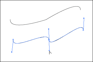
Simple in concept, the Add Anchor Point tool—which looks just like the Pen tool with a little + (plus sign) next to it—enables you to place additional anchor points on an existing path (see Figure 7.27). Each new point takes on the attributes of the path on which you click. If you add a point to a straight path, the new anchor point is a straight anchor point, and clicking a curved path results in a new smooth anchor point.
The Delete Anchor Point tool simply deletes existing anchor points. It also looks just like the Pen tool, except that it has a minus sign (–) next to it. If you click an anchor point with the Delete Anchor Point tool (see Figure 7.28), the point is removed, and Illustrator automatically joins the preceding anchor point with the next point on the path. If you were to select an anchor point and press the Delete key on your keyboard, the anchor point would be deleted, but the path would be broken at that point.

Did you Know?
Illustrator has a preference setting that automatically causes the Pen tool to change to the Add Anchor Point tool any time you mouse over an existing path. Likewise, the Pen tool automatically changes to the Delete Anchor Point tool when you mouse over an existing anchor point. This preference is turned on by default. Although this behavior is desirable at times, it can also get in the way. To turn it off, check the Disable Auto Add/Delete option in the General panel of the Preferences dialog box (see Figure 7.29).

What do you do when you already have an anchor point, but you need to change it from one type of point to another? You use the Convert Anchor Point tool. You can easily access this, the last tool from the Pen tool quartet, by pressing (Option) [Alt] when any of the Pen tools is active. Notice that the cursor changes to an inverted V shape.
This tool works the same way as the Pen tool; clicking a point converts it to a straight anchor point. Clicking and dragging on a point makes that point a smooth anchor point. To make a smooth point into a combination point, click and drag on a control handle (see Figure 7.30).
When you create paths, they aren’t always as clean or as smooth as you might like, especially when using the Pencil tool and drawing with a mouse. The Smooth tool (grouped with the Pencil tool) enables you to “get the kinks out” and get a smooth vector path. Use the tool to draw over any part of a selected path to smooth out that section of the path.
Sometimes a shape has many extra anchor points (as a result of autotracing, or an autotrace program such as Adobe Streamline). Sometimes entire paths need to be smoothed out as well. Although you can use the Smooth tool for certain applications, as mentioned previously, sometimes you want to apply those effects on a larger scale.
With any path or object selected, you can choose Object, Path, Simplify to remove extra anchor points and smooth out vector paths. You can specify that only straight lines be used (no curves), and you can also choose to show a preview of the original path, to compare how close the new simplified path will be to the original (see Figure 7.31). Making adjustments to the Curve Precision and Angle Threshold sliders will control how many anchor points are removed and how smooth the result will be.

No doubt you had more fun drawing the simple shapes discussed earlier than you did trying to make sense of the likes of the Pen tool. When it comes to creating more complex shapes, however, you can still use the primitive shape tools that are easy to use, along with a powerful collection of functions called Pathfinder. In fact, these functions are so useful that they have their own panel.
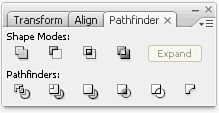
The idea behind the Pathfinder functions is that you can use several simple shapes to create a single, more complex shape. The Pathfinder panel is split into two rows of functions. The buttons on the top row are called Shape Modes, and they enable you to add, subtract, intersect, and exclude shapes. The buttons on the bottom row are referred to as Pathfinders, and they enable you to divide, trim, merge, crop, outline, and apply a Minus Back function (see Figure 7.32).
The shape modes are used primarily to create complex shapes from two or more other paths. To use these functions, you simply select the shapes you want to affect and click on the appropriate shape mode. There are four shape modes in Illustrator CS3:
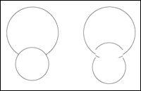
Add—. The most commonly used command, the Add shape mode combines all the selected objects into one object (see Figure 7.33).
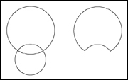
Subtract—. The Subtract shape mode subtracts the frontmost object in your selection from the shape behind it, leaving a hole cut out of it (see Figure 7.34).
Intersect—. The Intersect shape mode is used on two or more objects that overlap each other. When it’s applied, only the area where the objects overlap remains. The other parts of the objects are not visible (see Figure 7.35).
Exclude—. The Exclude shape mode is the exact opposite of the Intersect shape mode. When it’s applied to overlapping objects, only the parts that don’t overlap remain visible (see Figure 7.36).


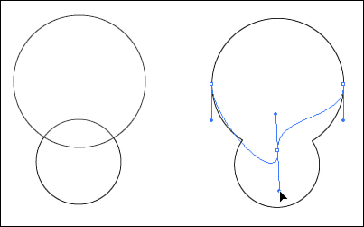
Shape modes are nondestructive, meaning that you can continue to edit the primitive shapes after you’ve applied a shape mode. Objects that have shape modes applied to them are called compound shapes. You can use the Direct Selection tool to select parts of a compound shape to edit them (see Figure 7.37).
If at any time you want to “flatten” a compound shape so that the individual primitive shapes are no longer accessible, select the compound shape and click on the Expand button in the Pathfinder panel (see Figure 7.38). Alternatively, if you want to create a flattened object to begin with, you can press and hold the (Option) [Alt] key while applying any of the shape modes.

Did you Know?
Illustrator’s compound shapes are similar to Photoshop’s shape layers (vector masks). In fact, you can copy an Illustrator compound shape and paste it into Photoshop as a vector shape layer. Likewise, you can copy a vector shape layer from Photoshop and paste it into Illustrator as a compound shape (see Figure 7.39).

The Pathfinder functions are primarily used for splitting objects into parts or deleting unwanted parts of objects. There are several kinds, each with a different purpose:
Divide—. The Divide Pathfinder cuts up any overlapping shapes into separate shapes wherever they overlap (see Figure 7.40). An invaluable tool, Divide enables you to split up objects quickly. Divide looks at each object and divides each overlap individually, so it makes no difference whether you’re dividing compound paths, groups, or whatever—they all become individual shapes. After Divide is applied, all the resulting objects are grouped together. You have to ungroup them if you want to work with each piece separately (or use the Direct Selection tool).
Trim—. The Trim function removes the parts of the back object that are behind front objects. It also removes the stroke (see Figure 7.41).
Merge—. The Merge function operates differently, depending on the fills of the selected objects. If the fills are all the same, the result is similar to what’s achieved with the Add shape mode, making the objects form one single (flattened) object. If the fills are all different, Merge works like the Trim function. If some of the objects are filled the same, the like objects are united and the rest are trimmed (see Figure 7.42).
Crop—. The Crop function removes any parts of selected objects that are not directly under the frontmost object (see Figure 7.43). The final result of the Crop function is similar to what you would see if you created a mask. The only difference is that the Crop function actually deletes the art that is not visible, unlike a mask, which just covers it up. Be careful before you run this command because you cannot retrieve the artwork that is cropped out.
Outline—. Choosing the Outline function converts all shapes to outlines and also divides the lines where they intersect, similar to a Divide function for strokes (see Figure 7.44).
Minus Back—. The reverse of the Subtract shape mode, Minus Back subtracts a part of an object based on what’s behind it (instead of what’s in front of it). This function is also not a shape mode, so the final result is a single flattened object (see Figure 7.45).


In typical paint programs, you use selection tools to select pixels. In Illustrator, things are a bit different—rather than pixels, we’re primarily interested in objects. Illustrator has several selection tools and selection methods, so let’s take a look at them.
The Selection tool (or the black arrow, as I like to call it because of its appearance) is used to select entire objects. You select an object simply by clicking on it. When an object is selected, you can move it by dragging the object.
You can select multiple objects by holding down the Shift key as you click on other objects.
The Shift key technique can really save time when you’re making certain selections, such as when you want to select all objects in your file except for one of them. In this case, you can simply select all and then Shift+click the one you want to deselect, and you’re done.
Another method of selecting objects with the Selection tool is called marquee selecting, in which you click on a blank area and then drag the mouse while holding down the mouse button. As you drag the mouse, a box appears. Any objects that fall within the marquee box become selected when you release the mouse button (see Figure 7.46). It’s almost like catching fish with a net.
Did you Know?
By default, you can click anywhere inside a filled object to select it. However, if you turn on the Object Selection by Path Only option in the Selection and Anchor Display Preferences (see Figure 7.47), you are able to select a path only by clicking on its path or outline. I find it useful to turn on this preference when I’m working in very complex illustrations because this option makes it more difficult to accidentally select unwanted objects.

The Direct Selection tool (or as I like to call it, the white arrow) is the selection tool used the most in Illustrator. In a few moments, you will see why. As you just learned, the Selection tool is used to select entire objects. The Direct Selection tool, on the other hand, is used to select parts of an object. If you click on a path and drag, only that path moves. The same applies when you click on an anchor point—only that anchor point moves (see Figure 7.48).

You can use either the Shift+click method or the marquee method to select multiple anchor points and move them at the same time.
Illustrator enables you to group several objects to make it easier to organize your artwork. However, the benefits of grouping objects go far beyond having art that is “neat” or organized. First, when you use the Selection tool to select one object in a group, the entire group is selected. This makes it easier to move objects around. Second, a group itself can have certain attributes or effects applied to it. Finally, groups can be nested. That means you can have a group inside another group (and so on).
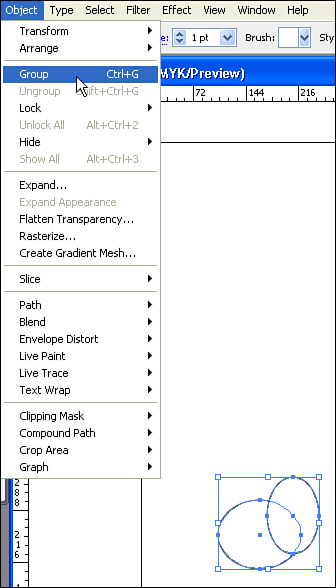
To make a group, select the objects you want to group, and choose Object, Group (see Figure 7.49). To release a group, select it and choose Object, Ungroup.
Groups are extremely helpful when you are working in complex documents, and grouping items as you create them is always a good idea. After you create a logo, for instance, group it. This way, you can move it around easily, and, more important, you won’t accidentally lose parts by trying to select each piece every time (inevitably, you’ll miss one or two parts).
When you double-click on any object in a group using the Selection tool, a gray box appears at the top of the window (see Figure 7.50). This gray box indicates that you’re in group isolation mode, and any new shape that you now draw automatically becomes part of the group. To get out of group isolation mode, click the arrow in the box. We talk more about group isolation mode when we cover Live Paint, later in “Live Paint Groups.”

The Group Selection tool is a variation of the Direct Selection tool. It is grouped with the Direct Selection tool and can be found by pressing and holding the mouse button on the Direct Selection tool in the toolbox. In complex illustrations, you might have nested groups that contain many groups. The Group Selection tool makes working with these groups easy.
Each time you click with the Group Selection tool, it selects the next higher group, giving you easy access to any group with a nested group.
As mentioned earlier, the Direct Selection tool is the most-used selection tool in Illustrator. If you switch back to the Direct Selection tool and press and hold the (Option) [Alt] key, you’ll notice that the cursor for the Direct Selection tool on your screen turns into the Group Selection tool. Releasing the (Option) [Alt] key returns you to the Direct Selection tool.
Now you have the power to select parts of an object, or, by simply holding down the (Option) [Alt] key, you can select an entire object or entire groups of objects. For 90% of your work, you never have to go back to the Selection tool (black arrow).
Using the marquee method for making selections with the Selection and the Direct Selection tools can be useful, but only if you’re okay with selecting objects that fall into a rectangular marquee area. The Lasso tool enables you to draw irregularly shaped marquees to select objects or parts of objects.
The Lasso tool works much like the Direct Selection tool, in that if an object falls completely within the boundaries of the marquee, the entire object becomes selected. But if only a portion of the object falls into that marquee area, only that portion of the object becomes selected (see Figure 7.51).

To use the Lasso tool, choose it from the toolbox and draw a marquee area. You don’t have to complete the marquee by drawing back to the point you started from because the Lasso tool completes the marquee selection area after you release the mouse.
Photoshop has a Magic Wand tool that’s used to select pixels of similar color. Likewise, in Illustrator the Magic Wand tool is used to select objects of similar attributes. Double-clicking on the Magic Wand tool in the toolbox opens the Magic Wand panel, where you can specify a Tolerance setting and specify to which attributes the Magic Wand is sensitive (see Figure 7.52).

Illustrator wouldn’t be incredibly useful if it were capable of creating only shapes with white fills and black strokes. It’s time to splash a bit of color on the topic of applying fills and strokes to objects in Illustrator.
You can specify colors for selected objects in Illustrator by using the Color panel. When expanded fully, the Color panel contains a fill and stroke indicator, color sliders, and a color ramp (see Figure 7.53). To specify a color for the fill of an object, you have to click on the fill indicator first. Likewise, to specify a color for the stroke of an object, click on the stroke indicator.

The Color panel can define colors in Grayscale, RGB, HSB, CMYK, and Web-safe RGB color modes. To switch among these color modes in the Color panel, choose from the list in the panel flyout menu (see Figure 7.54). Alternatively, you can Shift+click on the color ramp to cycle through the different supported color modes.

You can store saved colors in the Swatches panel (see Figure 7.55). To create a swatch, simply drag a color from the stroke indicator or the fill indicator in the Color panel into the Swatches panel. Illustrator also ships with numerous swatch collections, which you can access by choosing Open Swatch Library from the Swatches panel flyout menu.

You can create basically three kinds of swatches inside Illustrator: solid colors, gradients, and patterns.
Solid colors are simple and are really prerequisites for the other types of swatches. You can define a solid color just as mentioned previously, by specifying a color in the Color panel. However, you need to be aware of really two types of solid colors: process colors and spot colors.
A process color, by definition, is a color made up of a mix of colors. In the print world, a process color is one made up of different values of CMYK. In the Web arena, Illustrator would also consider an RGB color a process color.
You specify a process color for jobs you’d be printing in four-color process or publishing on the Web.
A variation of the process color, called a global process color (see Figure 7.56), enables you to easily track and update colors throughout your document.
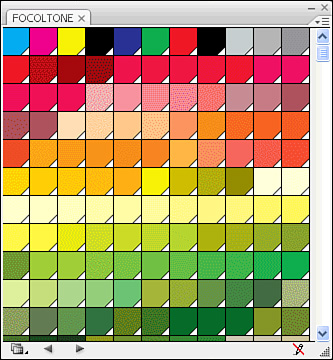
A spot color is a predefined ink color that you can either specify on your own or choose from a list such as Pantone, Focoltone, or Toyo. Spot colors also are referred to as custom colors. They are standard colors that have been designated to ensure color accuracy.
Spot colors have a single value, or a tint value, that determines the strength at which the ink will be printed. Spot colors are usually specified when you want to print a specialized ink (a metallic color, for example) or when you want to save money by printing a two- or three-color job (instead of having to print a full process–color job).
Illustrator ships with many standard custom color libraries, all of which you can load by choosing Open Swatch Library from the Swatches panel flyout menu.
Gradients are a powerful feature in Illustrator, enabling you to specify a fill of different colors blending with each other. Illustrator can create a gradient between just 2 colors or up to 32 colors. Gradients can be used to achieve cool shading effects or to add dimension to objects (see Figure 7.57).

You can apply a gradient to a selected object simply by selecting a gradient swatch from the Swatches panel. To create or edit a gradient, however, you need to open the Gradient panel. With the panel expanded fully, you will find a gradient swatch, an option to make the gradient linear or radial, fields for Angle and Location, and a gradient slider (see Figure 7.58).

You create a gradient in much the same way you create a color. Click on the Gradient swatch in the Gradient panel. Notice that under the gradient slider are icons that look like little houses. They are color stops, indicating the points at which a color is used in the gradient. To create a new color stop, click anywhere beneath the gradient slider. When a new color stop appears, you can drag it to the left or right. You can also drag any color from the Swatches or Color panel onto the gradient slider to create a color stop in that color. To change an existing color stop, either drag a new color directly on top of it, or click the color stop icon to select it and choose a new color in the Swatches or Color panel.
Notice also that little diamond-shape icons appear on top of the gradient slider. These indicate the location of the midpoint of the gradation. In other words, wherever the icon is, that’s the place where 50% of each color appears. You can drag the midpoint indicator left or right to adjust where the midpoint should be (see Figure 7.59).

After you’ve created the perfect gradient, click the New Swatch icon in the Swatches panel. After you create the new swatch, you should double-click it and give it a name. Illustrator gives your creations the names New Gradient Swatch 1, New Gradient Swatch 2, and so on, which don’t really offer any insight into what they are.
The Gradient tool in Illustrator is used to control the direction and placement of a gradient in an object or over several objects. After you fill an object with a gradient, select the Gradient tool and, with the object still selected, click and drag across the object in the direction you want the gradient to go (see Figure 7.60). The place where you begin dragging is the position where the gradient starts, and the place where you let go is the position where the gradient ends. If you stop dragging before you get to the end of the object, Illustrator continues to fill the object with the color at the end of the gradient.

Patterns can be real time savers. A pattern is a defined piece of art, or tile, created in Illustrator that, as a fill attribute, is repeated over and over again, much like wallpaper (see Figure 7.61).

Defining a pattern is a little different from defining gradients or colors. Instead of clicking the New Swatch icon, you drag your objects directly into the Swatches panel from the artboard. After you create a pattern swatch, remember to give it a unique name so you can identify it quickly when you need it.
When you’re creating a pattern design, remember that your object will be repeated over and over again, so be careful how you set it up. If you need extra space around your art (which is usually the case), create a rectangle and send it to the back of your artwork. Then select your art, along with the empty box in the background, and define the pattern. Illustrator treats a rectangle that’s at the bottom of the stacking order as a boundary for the repeat area of the pattern.
A stroke is the line that’s drawn around an object, and you can specify solid colors, gradients, or patterns to color a stroke. The Stroke panel is where you can control the actual settings for how a stroke appears (see Figure 7.62).

The most-used option in the Stroke panel is Weight. It determines how thick or thin the stroke is. Illustrator’s default is 1 point. For hairline rules, most people use 0.25 point (anything thinner probably won’t show up on an offset printing press).
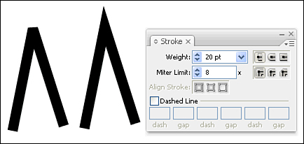
The Miter Limit option determines how far the stroke protrudes on a sharp corner. A thick line, for example, needs more room to complete a sharp point than a thin one does (see Figure 7.63).
Line caps determine the appearance of the ends of a stroked path (see Figure 7.64). This setting in the Stroke panel is used only for open-ended paths. By choosing different caps, you can make the ends either flat or rounded, or have the stroke width enclose the end of the path as well.

Line joins control how the stroke appears at each corner of the path (see Figure 7.65). You can choose from Mitered, Round, and Beveled options.

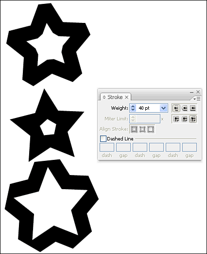
By default, Illustrator draws the weight of a stroke on the center of a path. That means a 20-point stroke results in 10 points applied to the inside of the path and 10 points to the outside of the path. However, you can use the Align Stroke buttons in the Stroke panel to specify that the weight of the stroke be applied entirely inside the path or entirely outside the path (see Figure 7.66).
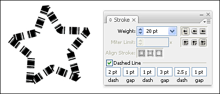
The last option in the Stroke panel, Dashed Line, can be one of the most powerful. Here you can specify dashed or dotted lines. Depending on what settings you have set for weight, line caps, and line joins, you can create a stitched line, a skip line, or almost anything. You control the dash and gap (the space between each dash) by entering numbers into the Dash and Gap fields at the bottom of the panel. If you’re using only one sequence, you can enter just the first two fields. Alternatively, you can enter up to three Dash and Gap settings to achieve complex dash patterns (see Figure 7.67).
For outlining and special effects, Offset Path is a great function. Offset Path creates an object that perfectly outlines, or traces, a selected path at an offset that you specify. To use it, select one or more objects and choose Object, Path, Offset Path. The Offset Path dialog box then appears. Enter an amount for the offset (you can use positive or negative numbers) and click OK. Note that Offset Path always makes a copy of your selection and does not affect the original.
Outline Path is another great feature that converts strokes into filled objects. Found in the same location as the Offset Path command, Outline Path works by creating a filled shape the size of the stroke width.
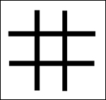
We’ve discussed groups, but Illustrator also has a special kind of group called a Live Paint group. Ordinarily, coloring objects in Illustrator requires the careful creation of closed vector shapes. For example, if you were to draw a tic-tac-toe board using four straight lines (see Figure 7.68), there would be no easy way to fill the middle section with a color, even though it appears to be a closed area. With Live Paint however, you can do so.
With the four lines selected, you could select the Live Paint Bucket tool (a paint bucket pouring into a small square) and then click on any of the paths to convert them to a Live Paint group. In a Live Paint group, any area on your screen that looks like a closed shape acts like one. You can then choose a color from the Swatches panel and click on the center region of the art with the Live Paint Bucket tool to fill the area. As you move the Live Paint Bucket tool, areas that can be filled with color are highlighted (see Figure 7.69).

Live Paint groups are also easier to use when making edits. You can switch to the Selection tool and double-click on the group to enter group isolation mode. Then you can use the Line tool to draw a new line through the middle of the group. Using the Selection tool, double-click outside the group to exit group isolation mode. You can use the Live Paint Bucket tool to apply color to the dissected regions.
The Live Paint Selection tool enables you to select regions or segments of paths and even delete them.
When creating freestyle art, there are sometimes gaps between the paths because not every path lines up perfectly. You might want to fill a region with color even if the region isn’t visibly closed. With a Live Paint group selected, you can choose Object, Live Paint, Gap Options, to specify that gaps of a certain size (which you define) will automatically close when creating filled areas (see Figure 7.70).

At any time, you can also expand a Live Paint group by selecting the group and choosing Object, Live Paint, Expand. This returns the objects to normal Illustrator vector objects.
Illustrator includes four kinds of brushes, all applied in the same way. The traditional way to apply a brush in Illustrator is to use the Paintbrush tool, which works similarly to the Pencil tool. Instead of just drawing a plain stroked path, the Paintbrush tool applies one of the four kinds of brushes.
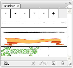
Brushes are stored in the Brushes panel (see Figure 7.71), and the truth is that you don’t need to use the Paintbrush tool to apply a brush at all. That’s because you can select an existing object and click on any brush in the Brushes panel to apply that brush stroke to the selected path. Of course, the Brush tool makes it easier to create more artistic brush strokes, but as you’ll soon see, certain kinds of brushes don’t require that kind of artistic touch.
The first kind of brush is the Calligraphic brush. A calligraphy pen has an angled tip, or nib, which, when used to draw or write, creates a tapered line that gets thicker or thinner, depending on the angle and direction of the stroke. The Calligraphic brush simulates this effect (see Figure 7.72).

To create a new Calligraphic brush, click on the New Brush icon in the Brushes panel and choose New Calligraphic Brush to get the Calligraphic Brush Options dialog box (see Figure 7.73).

In the Calligraphic Brush Options dialog box, you can specify the following settings:
At the top of the box, you can specify a name for the brush.
Directly under the name is a white box with a picture of an ellipse with an arrow going through it and two black dots on either side. This is the Brush Shape Editor. Simply click and drag on the arrow to rotate the brush shape and adjust its angle. Click and drag inward on the black dots to adjust the roundness of the brush shape.
To the immediate right of the Brush Shape Editor is an area that shows you a preview of your brush shape. Notice the three shapes, of which the outer two are grayed out and the center one is black. If you have variations set (see the next bullet item), the gray shapes illustrate the minimum and maximum values for the brush shape.
You can specify values for angle, roundness, and diameter numerically at the bottom of the dialog box. Each option can have one of three variation attributes: Random, in which Illustrator randomly changes the setting; Pressure, which enables you to determine brush shape by how hard you press with a pressure-sensitive pen and tablet; and Fixed, which assigns a constant value that you define.
The Scatter brush distributes predefined art along the path you draw with the Paintbrush tool (see Figure 7.74). To define a new Scatter brush, you have to start with a piece of art. When you’ve created the art you want to use for the brush, select the art and drag it into the Brushes panel. When the New Brush dialog box appears asking what kind of brush you want to create, choose New Scatter brush and click OK.

Illustrator then opens the Scatter Brush Options dialog box, where you can specify the behavior of the new Scatter brush (see Figure 7.75).

In the Scatter Brush Options dialog box, you can specify the following settings:
At the top of the box, you can specify a name for the brush.
Directly under the name are four options for which you can enter numerical values to specify the size of the art when it’s drawn on the path; the spacing between the art as it appears on the path; the scatter, which defines how far from the path the art can stray; and, finally, the rotation, which specifies the rotation of each individual piece of art on the path. You can set the rotation to be relative to the page or to the actual path itself. For each of these four settings, you can specify Fixed, Random, or Pressure, just as you could for the Calligraphic brushes. The Pressure option works only if you are using a pressure-sensitive tablet, such as a Wacom tablet.
The final option for the Scatter brush is Colorization. This option enables you to specify color changes to the art that appears on your painted strokes. Choosing None keeps the color consistent with the original color defined with the brush you have selected. To use the Hue Shift option, click the Eyedropper box, and click to choose a color from the art that appears in the box to the right. This procedure works on colored objects only, not black-and-white objects. Clicking the Tips button can help you see how the color changes are applied.
If you’re thinking that the Scatter brush seems similar to the brushes you created in Photoshop, you’re absolutely right. As you’ll see in “The Symbolism Tools,” there’s a more powerful feature in Illustrator, the Symbol Sprayer tool, that can create art that looks similar to the Scatter brush.
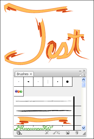
The Art brush differs from the Scatter brush in that the Art brush stretches a single piece of predefined art along a path (see Figure 7.76), whereas the Scatter brush litters the path with many copies of the art.
To define a new Art brush, you have to start with a piece of art. After you’ve created the art you want to use for the brush, select the art and drag it into the Brushes panel. When the New Brush dialog box appears asking what kind of brush you want to create, choose New Art Brush and click OK.
Illustrator then opens the Art Brush Options dialog box, where you can specify the behavior of the new Art brush (see Figure 7.77).
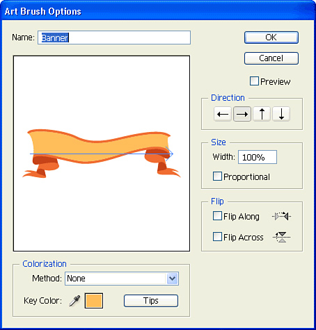
In the Art Brush Options dialog box, you can specify the following settings:
At the top of the box, you can specify a name for the brush.
Directly under the name is a white box with the art in it. Notice that an arrow goes through the art. This arrow indicates the direction the art is drawn on the path; you can edit it by clicking any of the arrows that appear to the right of the white box.
Below the Direction option is the Size option, in which you can specify what size the art appears on the painted path. If you select the Proportional option, the artwork retains is height-to-width relationship for the length of the stroke. You can also specify whether the art should be flipped along or across the painted path.
The final option for the Art brush is Colorization, which functions exactly like the Scatter brush does, as described earlier.
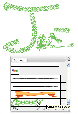
Apparently, three kinds of brushes in Illustrator just weren’t enough for the engineers over at Adobe, so they added a fourth—arguably the most powerful of the bunch. The Pattern brush applies patterns across a painted path (see Figure 7.78). What makes this different from any brush until this point is that you can define patterns with different attributes for corners and ends. We covered how to create patterns earlier in the chapter; when you have your patterns listed in your Swatches panel, you can define a Pattern brush by clicking on the New Brush icon in the Brushes panel and choosing New Pattern Brush.
Illustrator then opens the Pattern Brush Options dialog box, where you can specify the behavior of the new brush (see Figure 7.79).

In the Pattern Brush Options dialog box, you can specify the following settings:
At the top of the box, you can specify a name for the brush.
Directly under the name are five boxes, each representing a different tile of the pattern: Side, Outer Corner, Inner Corner, Start, and End. You do not need to define all five parts, and Illustrator uses the parts only when necessary. With a tile section selected, choose a pattern from the list that appears directly under the tiles.
As with the previous brushes, you can specify Scale and Spacing, as well as specify whether the pattern should be flipped along or across the path.
With the Pattern brush, you can decide how Illustrator fits the pattern to the path. Obviously, not every pattern will fit every path length perfectly. If you select Stretch to Fit, Illustrator stretches the pattern tiles to make the pattern fit seamlessly across the entire painted path. If you select Add Space to Fit, Illustrator does not adjust the size of the pattern tiles, but spaces them evenly across the painted stroke. Finally, the Approximate Path option adjusts the size of the path itself to fit the size of the pattern tiles.
The final option for the Pattern brush is Colorization, which functions exactly as it does for the Scatter and Art brushes, as described earlier.
In closing, if you find it hard to identify each brush type just by looking at the Brushes panel, you can opt to view the brushes by name. Choose List View from the Brushes panel flyout menu, and an icon on the far right of each brush listing indicates the brush type (see Figure 7.80).

Using layers in Illustrator enables you to better organize the objects in your file. Although it might not make much sense to spend time creating and working with layers to work on a simple logo, it certainly makes sense for illustrations or designs that are more complex.
Illustrator’s layers are specified in the Layers panel. When you start working in a new document, all artwork is automatically placed on a layer called Layer 1 (see Figure 7.81). To open the Layers panel, choose Layers from the Window menu. The order in which layers appear in the Layers panel is important: Layers that appear closer to the top of the panel appear above (or in front of) other objects that might appear on layers that are closer to the bottom of the Layers panel.

Some artists prefer to create several layers before they begin working, adding art to each layer as they progress. Others prefer to add or delete layers as necessary as they work on a project. Still others like to create the entire piece and then chop it into different layers afterward. As you’ll soon see, there are certainly some benefits to working with layers during the design process (instead of after the fact).
To create a new layer, click on the New Layer button at the bottom of the Layers panel. Illustrator creates the layer and assigns it a name. You can double-click on the layer to rename it, or instead you can (Option-click) [Alt+click] on the New Layers button to create a new layer and name it in one step. In either case, it’s a good idea to name your layers because trying to identify layers that are named Layer 1, Layer 2, Layer 3, and so on is difficult (to say the least).
To delete a layer, either click the layer in the Layers panel to highlight it and then click on the Trash icon at the bottom of the panel, or drag the layer itself onto the Trash icon. If you try to delete a layer that contains artwork on it, a warning dialog box appears, alerting you about the situation; Illustrator deletes the layer and its contents only with your permission.
You can duplicate a layer—and all the contents of that layer along with it—by clicking and dragging an existing layer onto the New Layer icon in the Layers panel.
As I mentioned earlier, there are certainly benefits to working with the Layers panel as you design your art. Let’s take a closer look at the Layers panel to better understand these benefits.
Each layer in the Layers panel has several icons, which enable you to perform certain functions (see Figure 7.82). We discuss these functions beginning on the far left of a layer listing.

On the far left, each layer has an icon that looks like an eye. Clicking on the eye toggles the visibility of that layer. Pressing the (Option) [Alt] key while clicking on the eye hides/shows all other layers at once.
The next icon to the right of the eye is a lock indicator. Click in the box to toggle the layer to be locked or unlocked. Pressing the (Option) [Alt] key while clicking on the lock locks/unlocks all other layers at once.
The next icon to the right of the lock is a disclosure triangle. Click on the triangle to reveal the contents of the layer. If there isn’t a triangle on a layer, there are no objects on that layer.
To the right of the disclosure triangle is a thumbnail icon that gives a graphical preview of the objects on that layer. Be aware that for documents with many layers, thumbnails can slow the performance of Illustrator because it has to draw each and every thumbnail.
To the right of the thumbnail is the layer name.
To the right of the layer name is a little circle. This is the target icon. For an effect or attribute to be applied to an object in Illustrator, that object (or group or layer) has to be targeted. Illustrator actually employs something called smart targeting that automatically does the targeting for you; however, sometimes you want to specifically target something yourself. To target a layer or an object, click once on the circle icon, which then appears with a circle outlined around it. Layers or objects that have an appearance applied to them display the circle as a shaded 3D sphere (which the Adobe engineers refer to as the “meatball”).
Finally, if you click on the far right of the layer, it selects all the objects in that layer. Selections are indicated by a colored square. This square can appear in two sizes. If all the objects on the layer are selected, you will see a large square, but if only some of the objects on a layer are selected, a smaller square displays. You can move artwork from one layer to another simply by dragging the colored square to a different layer. You can press the (Option) [Alt] key while dragging the square to copy the selected art to a different layer.
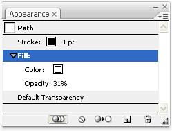
Ask me what I think the key is to getting a real grasp on using Illustrator, and I’ll tell you it’s the Appearance panel. That’s because the Appearance panel gives you the information you need to know about your targeted selections. For example, if you select a rectangle, the Appearance panel tells you that a path is targeted and indicates what the fill and stroke of that object are. More important, the Appearance panel tells you whether transparency settings or live effects have been applied to the object (see Figure 7.83). Later in “Live Effects” we cover exactly what live effects are, but examples are a soft drop shadow and a warp effect.

The Appearance panel also enables you to add multiple strokes or multiple fills to an object, a group, or a layer. To do so, simply choose Add New Fill or Add New Stroke from the Appearance panel flyout menu.
We’re going to be looking at the Appearance panel a bit more closely in “Live Effects,” but I wanted to point out that, just as with the Layers panel, items that appear in the Appearance panel represent the stacking order for those items. By default, an object’s stroke appears above the fill, but you can actually change that in the Appearance panel by dragging the fill to appear at the top of the stacking order. Following the same line of thinking, you can click on just the fill to highlight it and then apply an opacity setting that will be applied only to the fill, not to the stroke of that object (see Figure 7.84).
A mask conceals, or covers, parts of an object behind it, yet it reveals parts of the object behind it as well. For example, a mask that you wear to a masquerade party might cover parts of your face, yet some parts might not be covered. A mask in Illustrator works in much the same way: You can use just about any shape or object in Illustrator to mask other elements in your design. After a mask is applied, you can edit the art behind the mask or the mask itself, independently of each other.
You can apply basically three types of masks in Illustrator: a clipping mask, a layer clipping mask, and an opacity mask. Each of these masks has its own specific uses and capabilities.
The clipping mask, the simplest kind of mask in Illustrator, can be made of any vector shape. A clipping mask works in this way: You have a shape that sits on top of your objects. When the mask is created, any objects that fall within the boundary of the top shape (the mask) are visible, but anything that falls outside that boundary is hidden. It’s important to realize that the hidden art is not deleted—it’s still there, but it’s hidden from view.
To create a clipping mask, draw a shape for your mask and bring it to the front of the stacking order. Position your mask over the art you want the mask to affect and select both the art objects and the mask shape above it (see Figure 7.85). Then choose Object, Clipping Mask, Make to create the mask (see Figure 7.86). When the mask is applied, both the objects and the mask above it are grouped together; however, you can use the Group Selection tool to select just the mask or just the objects to make edits. This is useful when you want to reposition the mask to reveal a different part of the objects below it.

To release a mask (and have all the objects below the mask revealed again), select the group of the mask and objects, and choose Object, Clipping Mask, Release.
Layer clipping masks are very similar in concept to clipping masks, except that they are applied in the Layers panel and affect all items on a specific layer. To create a layer clipping mask, simply create a shape that’s on the same layer as the art you want to mask, and click on the layer listing in the Layers panel to highlight it. Then click the Make/Release Clipping Mask button at the bottom of the Layers panel (see Figure 7.87).
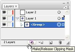
Any object you add to that layer automatically becomes masked as well. Likewise, any object you pull out of that layer no longer is masked. A mask object is indicated by a listing in the Layers panel with an underline. To release a layer clipping mask, highlight the layer in the Layers panel and click the Make/Release Clipping Mask button.
As Emeril Lagasse says, let’s kick it up a notch! Opacity masks are like clipping masks on steroids. First of all, you can use just about anything as an opacity mask—even gradients and photographs.
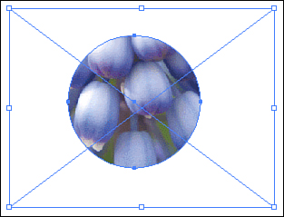
The same basic rules for clipping masks apply to opacity masks, in that you place the mask at the top of the stacking order and then select both the mask and objects under it before applying the mask.
When you have the objects selected, open the Transparency panel and expand the panel so you can see all the options. You’ll see a thumbnail of your selection on the left side of the panel. From the Transparency panel flyout menu, choose Make Opacity Mask. You’ll now see that a second thumbnail appears in the Transparency panel beside the original one, which is the mask itself (see Figure 7.88).
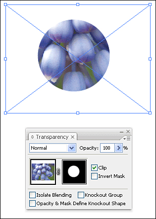
After an opacity mask is applied, you have several options in the Transparency panel:
To edit the art, click on the left thumbnail. You can tell that the thumbnail is highlighted if you see a black outline around it. Any edits you make on the artboard will affect the art objects themselves, and there’s no way for you to access or edit the mask object itself.
To edit the mask object itself, click on the right thumbnail. There are two ways you can tell that you’re editing the mask itself and not the art under it. The mask thumbnail is highlighted with a black outline, and the Layers panel changes to display only a single item—the opacity mask itself (see Figure 7.89). While you’re editing an opacity mask, you cannot make any edits to other art in your file.
Between the two thumbnails, there is a link icon (on by default). When the art and the mask are linked, they will be transformed together. So if you move the art, the mask will move with it as well (so that the appearance will be the same). You can click on the link icon to disable the link, at which time you can move the mask and the art independently.
The Clip option uses the shape of the mask to also clip the art under it (basically giving the same effect as a clipping mask in addition to the opacity levels).
The Invert Mask option enables you to reverse the luminosity values of the mask object. In simple terms, when you toggle this option, anything that was previously visible through the mask becomes hidden, and everything that was hidden becomes visible.

An object with an opacity mask applied to it is indicated in the Layers panel with a dashed underline. To release an opacity mask, select the masked object and choose Release Opacity Mask from the Transparency panel flyout menu.
Illustrator has five basic transformation functions: Move, Rotate, Scale, Reflect, and Shear. Illustrator also has a Free Transform tool and a feature called Transform Each that enables you to apply transformations to multiple objects with one click. You can also use the Transform panel, which makes for quick and precise transformations. I know it sounds confusing, but hang in there because this will all be second nature before you know it.
Before we talk about transformations, I want to point out one particular keyboard shortcut that is a real time saver. Holding down the (Cmd) [Ctrl] key at any time activates the most recent arrow selection tool you’ve used. For example, if you last used the Selection tool, pressing this keyboard shortcut while using any of Illustrator’s other tools temporarily activates the Selection tool. If the Direct Select or Group Select tool is active, you get the Selection tool; if the Selection tool is active, you get the Direct Selection tool.
When it comes to transformations specifically, you are always selecting objects and making minor changes to the art. Having to switch back and forth between the transformation tools and the selection tools is a pain. With the (Cmd) [Ctrl] key, the Selection tool is always just a keystroke away.
Although not necessarily a transformation, in that the actual object is changed, moving an object is considered a transformation because the coordinates of the object are being changed (we talk more about coordinates shortly, when we discuss the Transform panel).
You already learned one way to move an object: by clicking and dragging a selection. Illustrator also lets you move things more precisely. If you click and drag a selection and then hold down the Shift key, you can drag your selection only along a constrained axis in increments of ![]() .
.
Want to get even more precise? After you make a selection, you can use your keyboard’s arrow keys (up, down, left, and right) to “nudge” your selection incrementally. You can control how much each nudge is in the General Preferences panel by pressing (Cmd-K) [Ctrl+K] and changing the keyboard increment (see Figure 7.90).

Still not precise enough for you? If you want to move objects numerically, make your selection and then double-click on the Selection tool in the toolbox (the black arrow). In the resulting dialog box, seen in Figure 7.91, you can specify an exact amount to four decimal places. Entering negative numbers moves the object down or to the left. In this dialog box, you can also choose to move a copy of your object—and there’s a Preview button that enables you to view the results of the move before clicking OK.

There’s yet another way to move something: Illustrator’s Transform panel, which we’ll get to soon.
The four transformation tools—Rotate, Scale, Reflect, and Shear—are very similar. As you should know by now, before making any transformations, you must first make a selection.
With Illustrator’s default setting, when you make a selection, the object is highlighted with a rectangular shape that has hollow squares at the corners and the centers of each line (see Figure 7.92). This is called the bounding box, and it enables you to make certain transformations to the selection without having to select a different tool.

Clicking and dragging on any of the hollow squares enables you to scale the selection in that direction. Pressing the Shift key while dragging one of the hollow squares constrains the proportions of your selection. Pressing the (Option) [Alt] key when dragging scales the selection from its center.
If you position your cursor just outside any of the corner hollow squares, you’ll notice that your cursor changes from a straight arrow to a bent arrow. If you click and drag outside the object while the bent-arrow cursor is showing, you can rotate your selection around its center (see Figure 7.93). Pressing the Shift key while dragging constrains your rotations to increments of ![]() .
.

I’m not a big fan of the bounding box myself. For one, it was added to Illustrator a few versions back to appeal to users who had used other illustration tools, such as CorelDRAW, that featured this kind of functionality. Second, as you’re about to find out, there are specific scale and rotate tools in Illustrator that offer more powerful options. Finally—and most important, in my opinion—you can’t perform certain transformations when the bounding box is turned on. For example, say you want to drag an object by its corner to move it (I’ll explain in a moment why you would want to do that). With the bounding box turned on, if you drag from a corner, the object will scale rather than move. Illustrator has a snap-to-point feature that enables you to easily align objects as you position them. So you might want to grab a rectangle by its corner and move it to the edge of the page where the corner would snap to the edge of the page, making it easy to move objects with precision.
Anyway, I digress. The bottom line is that you’re now going to learn the most powerful way to perform scale, rotate, reflect, and shear transformations in Illustrator. The bounding box was really created for anyone who doesn’t plan to read this book. Although you can certainly keep the bounding box option turned on when using the other transformation tools, I’m going to suggest that you turn it off for now because it will be easier to learn the new tools that way. You can toggle the bounding box by pressing (Cmd-Shift-B) [Ctrl+Shift+B].
To apply a rotation, make a selection and press the R key on your keyboard. Right away, you’ll notice a new icon in the center of your selection, which is called your origin point. The origin point is the place from where your transformation begins. As you’ll soon see, all the transformation tools use an origin point, but specifically with the Rotation tool, your origin point dictates the center of your rotation.
If you want to rotate your selection around a point other than its center, you can redefine the origin point simply by dragging it to a new location, as seen in Figure 7.94.

You can set the origin point to just about any arbitrary point on your artboard. You’ll see why this is so useful as we progress with the transformation tools.
To rotate a selection, position your cursor a fair distance away from the origin point and click and drag with the mouse. You don’t necessarily grab the object itself (although you can), but if you click too close to the origin point, it will be difficult to accurately apply your rotation.
Pressing the Shift key while you drag constrains the rotation to increments of ![]() . Pressing the (Option) [Alt] key while dragging rotates a copy of your selection.
. Pressing the (Option) [Alt] key while dragging rotates a copy of your selection.
Probably the most frequently used transformation tool, the Scale tool enables you to change the size of your selected objects. You apply a scale transformation in much the same way as you do a rotate transformation. Make a selection and press the S key on your keyboard. If you want, you can move the origin point to a location other than the center of the selected objects.
To scale a selection, position your cursor a fair distance away from the origin point, and click and drag with the mouse. As you drag away from the origin point, your objects will scale larger. As you drag toward the origin point, your objects will scale smaller.
Pressing the Shift key while you drag constrains your objects to scale proportionally. Pressing the (Option) [Alt] key while dragging scales a copy of your selection.
Specifically with the Scale tool, Illustrator gives you the option to specify whether you want to scale any strokes or effects that are applied to your selection in addition to the object itself.
In a simple example, say you have a rectangle with a one-point stroke applied to it. By default, when you scale that rectangle, the stroke will remain at one point even though the rectangle is now a different size. If you double-click on the Scale tool in the toolbox, you’re presented with the Scale dialog box, where you can check the Scale Strokes and Effects box to have the stroke setting change size as well (see Figure 7.95). In a more complex example, if you have an effect such as a drop shadow applied to your selection, that effect’s settings will change size only if this option is turned on.

The Reflect tool enables you to flip or mirror your selected objects. This tool is most useful for creating symmetrical artwork. When you create one side of your art, simply flip a copy of it to complete the design (see Figure 7.96). Make a selection and press the O key on your keyboard (you can remember O for “opposite”). If you want, you can move the origin point to a location other than the center of the selected objects, which is common with the Reflect function because rarely will you reflect an object from its center.

To reflect a selection, position your cursor a fair distance away from the origin point, and click and drag with the mouse. As you drag, you will reflect your artwork.
Pressing the Shift key while you drag constrains your objects to reflect in increments of 45°. Pressing the (Option) [Alt] key while dragging reflects a copy of your selection.
The Shear tool enables you to skew your selected objects. You apply a shear transformation in much the same way as you apply the other transform functions. Make a selection and switch to the Shear tool (it’s found grouped with the Scale tool in the toolbox). There’s no keyboard shortcut assigned to this tool (although if you find yourself using this tool often, you can assign one to it). If you want, you can move the origin point to a location other than the center of the selected objects.
To shear a selection, position your cursor a fair distance away from the origin point and click and drag with the mouse. As you drag away from the origin point, your selection skews (see Figure 7.97).

Pressing the Shift key while you drag constrains your selection, and pressing the (Option) [Alt] key while dragging shears a copy of your selection.
Sometimes you need to make a precise transformation, such as rotating something 38°, or scaling something 221%. In those cases, you can apply transformations numerically by making your selection and then double-clicking on the transformation tool you need to use. A dialog box appears where you can enter specific values and choose to apply the transformation to your selection or to a copy of your selection.
When you double-click on a tool to apply a transformation numerically, the origin point for that transformation is always the center of the selection. If you want to apply a transformation numerically and you also want to specify an origin point, make your selection, choose the appropriate transformation tool, and click where you want the origin point to be while holding down the (Option) [Alt] key.
If your selection has a pattern fill applied to it, you can choose to transform both the object and the pattern, just the object, or just the pattern (see Figure 7.98). By default, Illustrator scales just the object, not the fill pattern. When you’re applying transformations via any of the transform dialog boxes (see the preceding subsection, “Going by the Numbers”), there’s a check box where you can specify whether pattern fills are transformed. Alternatively, you can press and hold the tilde (~) key (usually near the Escape key) as you’re dragging with any of the transform tools. This works even when you’re dragging with the Selection tool to move something.

Admittedly, I was a bit unkind to the bounding box feature in Illustrator earlier in this chapter. The truth is, there’s a tool that offers similar functionality to the bounding box in Illustrator—yet is far more powerful—called the Free Transform tool.
To use the Free Transform tool, make a selection and press the E key on your keyboard, or choose the Free Transform tool from the toolbox. Unlike with the other transformation tools, you can’t change the origin point when using the Free Transform tool.
The Free Transform tool enables you to perform a plethora of functions, which I’ve conveniently listed for you here:
Click inside the bounding box and drag to move the selection.
Click outside the bounding box and drag to rotate the selection.
Click and drag on any of the four corner handles to scale the selection. Press the Shift key to constrain proportion. Press the (Option) [Alt] key to simultaneously scale the opposite side of the selection.
Click and drag on any of the middle four handles to scale horizontally or vertically. Press the Shift key to constrain proportion. Press the (Option) [Alt] key to simultaneously scale the opposite side of the selection.
Click and drag on any of the four corner handles and press the (Cmd) [Ctrl] key to distort your selection. Press the (Option) [Alt] key to simultaneously distort the opposite side of the selection. Make sure you click on the handle first and then press the (Cmd) [Ctrl] key.
Click and drag on any of the four middle handles, and press the (Cmd) [Ctrl] key to skew your selection. Press the (Option) [Alt] key to simultaneously skew the opposite side of the selection. Make sure you click on the handle first and then press the (Cmd) [Ctrl] key.
To apply a transformation with the Free Transform tool, simply deselect your objects, and you’re done.
The Transform Each function offers two excellent benefits: the capability to perform scale, move, rotate, and reflect transformations simultaneously, and the capability to transform each object in a selection independently of the others. Let’s take a closer look.
First, making multiple transformations is a snap when you use Transform Each. Make a selection and choose Object, Transform, Transform Each to bring up the Transform Each dialog box (see Figure 7.99). Here, you can specify measurements for scaling, moving, rotating, and reflecting your selection. A Preview box enables you to view your transformation in real time. You’ll see in a minute how the Transform Each feature is more powerful than you might think.

The second benefit I mentioned was the capability to transform multiple objects individually. To demonstrate, I’ve created a grid of squares (see Figure 7.100). If you select all the squares and use the Rotate tool to rotate the selection 45°, the entire selection rotates as one—sharing a single origin point (see Figure 7.101). However, if you apply the Transform Each function to the same selection and specify a 45° rotation, each square rotates individually—each with its own origin point (see Figure 7.102).


The Random button in the Transform Each dialog box transforms each object a little differently, making for an irregular, almost hand-drawn look. If you have the Preview box checked, you can see how the objects will be affected. Unchecking and then checking the Random option gives different results each time (it truly is random!).
Simply because there aren’t already enough panels in Illustrator, you can also apply transformations via the Transform panel (see Figure 7.103). In truth, this panel is quite valuable because it enables you to precisely position artwork on your page, using x, y coordinates. No other transform function in Illustrator offers that capability. On the left side of the panel is a proxy you can use to specify an origin point, and to the right is a lock icon that enables you to automatically scale objects proportionally. The Transform panel is also accessible via the Control panel (click on the X or Y next to the coordinate fields).

The Transform Again command enables you to repeat the last-applied transformation. To learn how this feature works, try creating tick marks in the shape of a circle—like what you’d find on a clock or a compass.
Begin by drawing a single tick mark.
Press the R key to choose the Rotate tool, and (Option-click) [Alt+click] below the mark to specify a numeric rotation while setting a custom origin point (see Figure 7.104).
Enter a value of 30° for the rotation and click the Copy button.
Press (Cmd-D) [Ctrl+D] repeatedly until all the tick marks have been created (see Figure 7.105).
![Positioning the cursor to (Option-click) [Alt+click] to define a custom origin point and bring up the Rotate dialog box, all in one step.](http://imgdetail.ebookreading.net/career_development/career_development_detail1_2/9780672329340/9780672329340__sams-teach-yourself__9780672329340__graphics__07fig104.jpg)
Take what you’ve learned until now about transformations, and you’ll quickly see how powerful this feature can be. You can use Transform Again after you’ve applied a transformation using the Transform Each command, so you can even use this command to repeat multiple transformations at once.
While we’re talking about moving artwork around, I should mention that there are plenty of times when you need to align objects—either to each other or to the artboard itself. The Align panel (see Figure 7.106) is perfect for this task and for distributing objects as well. You can find the Align panel in the Window menu (by default, it’s clustered with the Pathfinder and Transform panels).

The icons in the top row in the panel are alignment functions. Simply select multiple objects and click on the icons to align them as specified. If you’re trying to align an object to the artboard (for example, centering an item on the page), you can choose the Align to Artboard option by clicking the Artboard pop-up menu in the lower-right corner of the panel. This function is actually a toggle, so your objects will align to the artboard until you go back to the panel and disable the feature.
The buttons in the second row of the panel are distribution functions. After you select a range of objects, clicking on these buttons evenly distributes them, using the objects on the extreme ends as anchors. The objects that fall in the middle magically spread evenly between the two anchors (see Figure 7.107).

Using the horizontal and vertical spacing buttons in the bottom row of the panel, along with the spacing field, you can specify to distribute objects a set distance from one another.
You’ll notice that when you’re aligning several objects, they all shift when they are aligned. However, sometimes you might want to align several objects to a specific object. In other words, you want to have one object remain stationary and all other objects align to that one object.
You can accomplish this task in Illustrator by defining a key object. When you’ve selected all the objects you want to align, click on the object to which you want all the other objects to align. Then align your objects as you would normally with the buttons on the Align panel. After you’ve defined a key object, you can choose a different one simply by clicking on a different object. You can also choose Cancel Key Object from the Align panel flyout menu.
One of the most powerful features added to Illustrator over the years is symbols. A symbol is a saved set of objects that can be referenced within a document. That probably sounds vague, so I’ll give you an example. Say you create a company logo, which is made up of several objects. You can define that completed logo as a symbol, which you can then reuse as many times as your heart desires within your document. Each instance of the symbol is a reference or alias of the original art that you defined. If you ever update or modify the symbol, all the instances automatically update as well.
Defining a symbol is easy. Simply create your art and then drag it into the Symbols panel (which you can find in the Windows menu). After you’ve defined a symbol (see Figure 7.108), you can delete the art you created because you can always access that art again later. Double-click on a symbol in the Symbols panel to rename it.
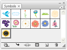
To place a symbol instance, drag it from the Symbols panel onto your artboard. You can apply any transformation to a symbol instance, and you can also apply settings from the Transparency panel. You’ll always be able to tell a symbol instance from actual art because an instance has a square bounding box when you select it with the Direct Selection tool (see Figure 7.109).

If you want to edit a symbol, you can drag it onto your artboard and then click on the Break Link to Symbol button (a broken chain icon) at the bottom of the Symbols panel. Doing so disassociates the art from the symbol, and you’ll have access to the art objects themselves. You can then make any changes or modifications to the art.
If you want to redefine a symbol, you can first edit it, as mentioned previously, and then select the art. Then, in the Symbols panel, click on the symbol you want to redefine. You’ll know that the symbol is selected when you see a black outline around it. Then choose Redefine Symbol from the Symbols panel flyout menu.
To save your own library of symbols, create a document and define a collection of symbols. When you’re done, choose Save Symbol Library from the Symbols panel flyout menu and give your collection a name. The next time you launch Illustrator, your symbol library appears in the list of libraries you can access from the Open Symbol Library option in the Symbols panel flyout menu.
Before you learn about this next feature, I just want to say that this feature comes with a disclaimer attached to it. It’s extremely fun and addictive. If you were intrigued by the use of symbols, this will blow your socks off. Okay, enough talking the talk—let’s get to walking the walk.
The symbolism tools are a collection of tools that enable you to exploit the power of symbols in a very graphical and natural way. There are eight symbolism tools in all (see Figure 7.110). The first one, the Symbol Sprayer tool, enables you to add symbols to your page, and the remaining seven tools are used to adjust symbols that are already placed on your page.

To use the Symbol Sprayer tool, select the tool from the toolbox and then open your Symbols panel. Select a symbol (which will be indicated by an outline), and then click and drag your mouse on the artboard to start flooding your screen with symbols (see Figure 7.111). Notice that when you’re using the Symbol Sprayer tool, rather than having multiple instances of symbols placed on your page, a single symbol set is created. A symbol set acts as one single object (which you can clearly see if you change your view to Outline mode). If you click and drag the mouse again with the symbol set selected, more symbols will be added to your symbol set. Press and hold the (Option) [Alt] key while dragging to remove symbols, if you’ve added too many.
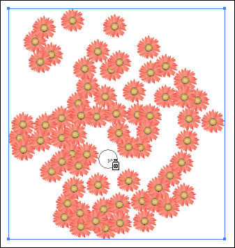
The remaining seven symbolism tools enable you to adjust and edit the symbols inside a symbol set:
Symbol Shifter—. This tool enables you to move symbols in a very organic fashion. It’s almost like your cursor is a magnet, and as you click and drag, you can push symbols in a specified direction (see Figure 7.112). Pressing and holding the Shift key while using this tool changes the stacking order of the symbols.
Symbol Scruncher—. This tool enables you to make the symbols sit closer to each other, making the overall result more dense. Pressing and holding the (Option) [Alt] key while using this tool reverses the effect and pushes symbols farther away from each other.
Symbol Sizer—. This tool enables you to enlarge the symbols as you click and drag over them. Pressing and holding the (Option) [Alt] key while using this tool reverses the effect and scales symbols to be smaller.
Symbol Spinner—. This tool enables you to rotate the symbols as you click and drag over them. As you drag, you’ll see arrows appear indicating the direction the symbols will spin.
Symbol Stainer—. This tool enables you to colorize the symbols as you click and drag over them. With the Symbol Stainer tool selected, choose a color from the Color panel or the Swatches panel. Then click and drag within your symbol set. You can change colors as often as you like.
Symbol Screener—. This tool enables you to reduce the opacity level of the symbols as you click and drag over them (making them transparent). Pressing and holding the (Option) [Alt] key while using this tool reverses the effect and increases the opacity level of the symbols.
Symbol Styler—. This tool enables you to apply graphic styles to symbols as you click and drag over them. It works similarly to the Symbol Stainer tool. With the Symbol Styler tool selected, choose a style from the Graphic Styles panel and then click and drag within your symbol set.

By the Way
When you’re continually switching between the different symbolism tools, it can be tiring traveling back to the toolbox each time just to select a different tool. With any of the symbolism tools already selected, try this instead: (Option+right-click) [Alt+right-click]. When the circle of tools appears (see Figure 7.113), simply move your mouse over the tool to which you want to switch and let go.
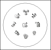
As you can see, these tools are not only easy and fun to use, but quite useful as well. Try using a range of different symbols to achieve natural and organic effects. The Hair and Fur and the Nature symbol libraries that Illustrator ships with contain some great symbols to use.
Illustrator has many of the text features you will also find in InDesign. Illustrator can create two kinds of text objects. The first is called point text, which is the simpler of the two. You create point text by selecting the Type tool and clicking on a blank area on your artboard. You’re presented with a blinking cursor, and you can begin to enter text immediately. Illustrator calls this point text because your text is aligned by the point that was created when you clicked with the Type tool (see Figure 7.114). Point text does not reflow, meaning that as you continue to enter text, the line grows longer and longer, and doesn’t break to a second line (unless you press Return or Enter).

The second kind of type object that Illustrator can create is called area text. There are two basic ways to create area text in Illustrator: either select the Type tool and click and drag with the tool to draw a box, or select the Type tool and click inside any existing closed vector path. Again, you’re presented with a blinking cursor, where you can begin entering text. The difference here is that when your text gets to the boundary of the shape, the text flows to the next line automatically (see Figure 7.115).

Area text also has specific functionality that point text does not, and you can access some of those functions by selecting a text area object and choosing Type, Area Type Options (or by double-clicking the Type tool icon) to bring up the dialog box (see Figure 7.116).

Area text can also be threaded, meaning that you can link several area text objects so that the text flows from one to the next. Every area text object has an in-port box and an out-port box. Just as in InDesign, if your area text object isn’t large enough to display all of your text, the out-port box is colored red with a plus sign, indicating that there’s more text (see Figure 7.117). You can either enlarge the area text object or use the Selection tool to click on the out-port box and then click on another object, to make the overflow text continue into that object.
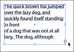
There’s a third kind of text object in Illustrator: type on a path—although in reality, it’s a kind of area type object. To create text that follows along the outline of a vector path, select the Type on a Path tool and click on any path (it can be open or closed). You’ll get a blinking cursor, where you can begin typing.
You can adjust three distinct functions when setting type on a path (see Figure 7.118):
In- and out-port boxes—. As with area text, Type on a Path objects can also flow from one path to the next.
Start and end points—. You can determine where text begins and ends on a path by dragging these vertical bars with the Direct Selection tool.
Center point—. Type can flow along either side of a path, and you can choose which side by using this point. Click and drag the point to the side of the path you want the text to flow along. This point also enables you to position the center of the text.
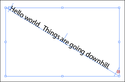
Of course, it wouldn’t be much fun if you were forced to use 12-point Myriad Pro for every text object in your document, so it’s nice to know that Illustrator’s text-formatting capabilities are on par with those found in InDesign. Because much of the functionality between Illustrator and InDesign is consistent, I discuss these features briefly here; you can refer to Chapter 8, “Using Adobe InDesign CS3,” for more detailed information.
Open the Character panel by choosing Window, Type, Character. Here you can specify font information (see Figure 7.119), type size, leading (pronounced ledding, which is the amount of space between lines), kerning, underline, and more.

Open the Paragraph panel (see Figure 7.120) by choosing Window, Type, Paragraph. Here you can specify paragraph information such as alignment, justification, composition method, indents, spacing, and more.

OpenType is a new font standard that really takes typography to a whole new level. Illustrator ships with more than 100 OpenType fonts, so you have a head start on getting to use them. Type 1 fonts (PostScript) have a limit of 256 glyphs per font. This is why Type 1 fonts always had these Expert font collections—there was simply no way to store all of those extra glyphs in a single font file. OpenType fonts, on the other hand, have a limit of 65,000 glyphs per font file (yes, 65,000—that’s not a typo). This gives type designers the freedom to add all of these cool variations of letters, swashes, ligatures, fractions, and the like to their type designs. Probably the most important aspects of OpenType fonts are that they are stored in a single file (instead of separate files for screen fonts and printer fonts) and they are cross-platform compatible (so a single file can be used for either Mac or Windows).
Illustrator has full support for OpenType fonts and also has added functionality that enables you to take advantage of the special features OpenType offers. You can access these features through the OpenType panel (which you can find in the Windows, Type submenu). To use it, simply select a range of text and click on the buttons at the bottom of the panel (see Figure 7.121). If the font you’re using contains swash characters, for example, those characters automatically appear. The same applies for fractions, ordinals, and other special type treatments.

If you want to find a specific glyph character in a font, you don’t have to try pressing every character combination on your keyboard to find it. Choose Type, Glyphs to open the Glyphs panel (see Figure 7.122). From the pop-up menu at the bottom of the panel, choose a typeface; every glyph present in that font displays in the panel’s window. If you have a blinking text cursor anywhere in your document, double-clicking on any glyph in the Glyphs panel places that glyph in your text string.
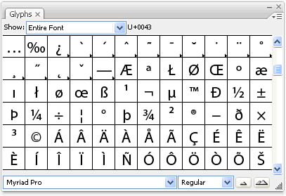
Paragraph and character styles enable you to easily style and format type. It’s also a way to consistently manage and update text formatting across your entire document. You can find the Paragraph Styles panel by choosing Window, Type, Paragraph Styles. The Character Styles panel appears in the same submenu. Refer to Chapter 8 for information on how to define and use paragraph and character styles.
Sometimes you want to edit actual character shapes in Illustrator. For example, you might start off designing a logo with some text, and then you want to make adjustments or modifications to the shapes of the letters themselves. To convert text to editable vector paths, select your type with the Selection tool (not the Type tool) and choose Type, Create Outlines (see Figure 7.123). You can convert only an entire point text object or an entire area text object to outlines—there’s no way to convert just a few characters in a text string.

Effects are a wide range of options you can apply to your objects. For example, you can apply soft drop shadows, 3D extrudes, warping, Gaussian blurs, feathering, and more. What makes these effects so unique is the way they are applied in Illustrator. Effects are applied to objects as appearances, leaving the original objects intact. For example, you might draw a plain rectangle and apply a warp effect to it. The rectangle will appear as being warped, but behind the scenes, it’s still a rectangle (see Figure 7.124). If you edit the rectangle, the effect that was applied to it simply updates to reflect the change. This also means that at any time, you can remove the effect completely and be left with the rectangle you created. For this reason, effects in Illustrator are referred to as live effects.
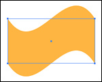
As mentioned before, effects are applied as appearances, so when you apply an effect to an object, that effect shows up in the Appearance panel when that object is selected (see Figure 7.125). As you’ll soon see, you will be applying a new effect to an object by choosing it from the Effect menu. However, when you want to edit an effect that you’ve already applied, you have to double-click on the effect item that appears in the Appearance panel.

Live effects can be applied to objects, but they can also be applied to groups or layers. To apply an effect to a group or a layer, you have to specifically target the group or layer in the Layers panel, which we discussed earlier in “The Layers Panel.” If a layer has an effect applied to it, for example, any object you add to that layer automatically takes on that effect attribute.
There’s a wide variety of effects in Illustrator, and some of them (Gaussian Blur, for example) are raster effects. Some effects (such as Drop Shadow) can also be applied to placed images. In fact, effects can also be applied to text without having to convert the text to outlines. Let’s take a look at some of the more popular live effects found in Illustrator.
The capability to create 3D graphics is not only exciting, but it’s also fun (and extremely addictive). I should emphasize that the 3D you’re about to learn isn’t just some cute effect, but real 3D rendering, including extrusions, bevels, revolves, and something called artwork mapping. If these terms sound foreign to you, don’t worry—you’ve been doing great so far, and I’m sure you’ll catch on to this as well.
To start off, 2D graphics have two coordinates, referred to as x and y values, usually indicating width and height. In addition to the x, y coordinate, 3D graphics have a third, referred to as the z value, which indicates depth. When describing 3D graphics, the x, y, and z values are usually referred to as axes rather than values. From now on, when talking about 3D, we’ll refer to these settings as the x-axis, the y-axis, and the z-axis.
The 3D Extrude effect adds dimension to your selected object. To apply the effect, make a selection and choose Effect, 3D, Extrude and Bevel. In the 3D Extrude and Bevel Options dialog box, click on the Preview button so you can see what your selected art will look like with the effect applied (see Figure 7.126).

At the top of the dialog box is the track cube, which you can use to rotate your object in 3D space. To use it, click and drag anywhere on the cube, and you’ll see a wireframe (outline) of your object on your screen update as you drag with the mouse. If you move your mouse over any of the edges of the track cube, you’ll notice that the edges highlight in red, green, or blue (see Figure 7.127). Clicking and dragging on these highlighted lines constrains the track cube to rotate the shape only along the x-, y-, or z-axis. Right above the track cube is a pop-up menu that contains several predefined views for your object.

The Perspective slider controls lens distortion. If you press and hold the Shift key while you drag the slider, you will see your art update in real time.
The Extrude Depth setting determines how far back in space your object will extend. Here also, you can press the Shift key while adjusting the slider to see real-time feedback. Press the Cap buttons to add and remove end caps on the front and back of your extruded object.
A bevel is a chiseled edge you can apply to your 3D object. Bevels are added only to the front surface and the back surface. To apply a bevel, choose one from the Bevel pop-up menu (see Figure 7.128). Illustrator ships with several predefined bevels, although you can create your own if you dare (instructions for how to do so can be found in the Bevels.ai file found in the Illustrator Plugins folder). After you’ve applied a bevel from the pop-up menu, you can specify a height for the bevel as well. To remove a bevel that you’ve already applied, choose None from the Bevel pop-up menu.
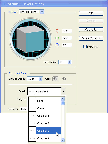
Illustrator’s 3D effect also lets you choose a surface type for your object from the Surface pop-up list (see Figure 7.129). By default, the Plastic Shading option is chosen, which gives your shape a glossy, reflective look. Choose Diffuse Shading for a surface that is matte in appearance. You can also choose to not shade your object at all by choosing No Shading. Finally, you can specify to have your 3D object display as a wireframe.

In an effort to make the 3D feature as easy to use as possible, Adobe created the 3D Options dialog box in two parts. If you click on the button marked More Options, you’ll see some additional 3D features from which to choose (see Figure 7.130).

To create realistic shading and highlights on a 3D object, Illustrator utilizes lighting effects. The sphere that appears in the lower left of the dialog box is a representation of your graphic, and you can position a light to shine and illuminate your object from any direction. Making adjustments to the lighting of your object can change its appearance dramatically. To adjust the position of the light, click and drag on the light and move it around to different parts of the sphere. Pressing and holding the Shift key while you drag the light enables you to see a preview of the result in real time.
You can also add multiple lights by clicking on the New Light button under the sphere (see Figure 7.131). To delete a light, select it on the sphere and click on the Trash button.
If you’re working with spot colors, you can check the Preserve Spot Colors option, which uses black as a shade color and sets that black color to overprint. You need to have the Overprint Preview mode turned on to see the correct results on your screen.
Ordinarily, Illustrator draws only the parts of a 3D object that are visible to you. For example, if the back of a box isn’t visible in the view you’ve specified with the track cube, it won’t be drawn (unless you change the view again, of course). Illustrator does this to save render time. However, you can force Illustrator to draw these hidden sides by checking the Draw Hidden Faces option. This option is useful when you’re creating 3D objects that are transparent (and you want to see through the front of the object to the back). It’s also useful when you want to break apart the different sides of the object after you’ve applied the effect (something called Expand Appearance, which we cover later in “Expanding an Appearance”).
The 3D Revolve feature revolves the profile of an object you draw in Illustrator around an axis to produce a 3D shape. For example, you might draw the profile of a vase and then use the 3D Revolve effect to create a realistic vase (see Figure 7.132).

To apply this effect, select the profile you’ve drawn, and then choose Effect, 3D, Revolve. When the 3D Revolve Options dialog box appears, check the Preview button so you can see how your object will look with the Revolve effect applied (see Figure 7.133).

You can rotate your object in 3D space the same way we discussed when talking about the 3D Extrude effect. Use the track cube to position your artwork to your liking, and use the Perspective setting to apply lens distortion.
The Angle setting determines how far Illustrator will apply the Revolve effect around the axis. By default, this is set to 360° (a full, complete revolve); however, you can adjust this number to be lower, in which case you’ll see a part of your shape removed, or “cut out” (see Figure 7.134).

We’ve mentioned that the Revolve effect uses an axis, almost as an origin point, which the profile is revolved around. By default, the axis is set to the leftmost part of the object. However, you can choose to specify the rightmost part of the object as your axis. Additionally, you can specify an offset, meaning that you can choose to move the axis a specified amount from the edge of your object. This is useful if you want to create a hole that goes through the center of your object.
The 3D Rotate effect enables you to rotate your object in a 3D space, but without adding any depth (extrusion) to it. You can apply this effect by making a selection and choosing Effect, 3D, Rotate. The settings in the 3D Rotate Options dialog box are a subset of what appears in the 3D Extrude and Bevel Options dialog box.
What sets Illustrator’s 3D feature apart from any of its competitors is something called artwork mapping, which is the capability to wrap 2D art around a 3D object. For example, you might want to use the 3D Revolve effect to create a vase, and with artwork mapping, you could also place a label onto the surface of that vase (see Figure 7.135).
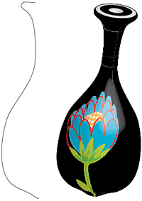
The first step in using the artwork mapping feature in Illustrator is to define a symbol. Illustrator uses symbols to map art onto a 3D surface, so if you want to place a label onto a 3D rendering of a bottle, you first have to define your label as a symbol. Earlier in “Using Symbols,” we discussed how to define and modify symbols.
After you’ve defined a symbol, create your 3D object by using either the 3D Extrude and Bevel effect or the 3D Revolve effect. In the 3D options dialog box, click on the Map Art button (it’s right under the Cancel button); you’re presented with the Map Art dialog box (see Figure 7.136). Check the Preview button to see the results onscreen as you apply effects.
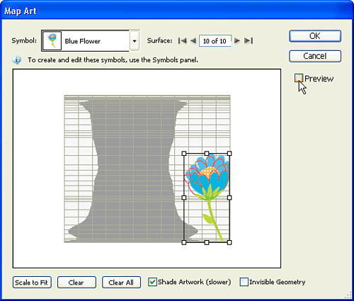
When you create a 3D object, there are several sides to the object (for example, a cube has six sides). When you want to map art in Illustrator, you first have to indicate on which side of the object you want the art to appear. Use the arrows at the top of the dialog box to cycle among the different sides of an object. In the window area of the dialog box, you’ll see the shapes of the different sides. Shaded areas indicate the parts of the objects that are hidden from view (for example, the back side of a cube). Illustrator also draws a red outline on the artboard to indicate the side of the object that is chosen.
When you’ve found the side of the object you want, choose a symbol from the Symbol pop-up menu. If you defined a symbol earlier, it will appear in this list.
You can then position the art by dragging it or by using the bounding box handles to scale or rotate it. The Scale to Fit button reduces or enlarges the symbol to fit the entire surface that is selected. A single symbol cannot be wrapped around multiple surfaces—each surface is basically on its own. You can then switch to another surface and apply a symbol, and so forth.
The Shade Artwork option also applies lighting and shading effects to your artwork. The Invisible Geometry option actually hides the 3D shape itself, showing only the mapped art, which can be used to create some interesting effects.
When you’re happy with the settings, click OK to apply the Map Art settings, and then click OK to apply the 3D settings. Because Illustrator uses symbols for artwork mapping, if you were to modify the symbol that you used, it would automatically update on the 3D object (you don’t have to reapply the mapped art).
To rasterize vector artwork using an effect, choose Effect, Rasterize. The Rasterize effect (see Figure 7.137) enables you to convert a vector into a raster as an effect, which is pretty cool when you think about it. The underlying shape is still a vector shape, but the result is a raster. You can specify the resolution for the raster as well as other settings, such as antialiasing.
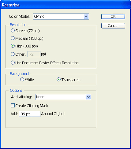
The live effects you will utilize most often are found in the Effect, Stylize submenu. Things such as arrowheads, soft drop shadows, and rounded corners are all found here.
To add arrowheads at the ends of a selected path, choose Effect, Stylize, Add Arrowheads. In the resulting dialog box (see Figure 7.138), you can specify a wide variety of arrowheads to appear at the start, the end, or both parts of a vector path. You can also choose to scale the arrowhead to be bigger or smaller, to your preference, by using the Scale value.

To add a soft drop shadow to a targeted selection (text and images included), choose Effect, Stylize, Drop Shadow. In the dialog box (see Figure 7.139), choose an X Offset value and a Y Offset value (how far the shadow falls from the object) and a Blur value (how soft the shadow is). You can choose a color for the drop shadow as well (including spot colors) by clicking on the Color box.

To apply a feathered edge to a selected vector object (see Figure 7.140), choose Effect, Stylize, Feather, and specify a value for the feather (higher numbers result in softer edges). Remember that to edit a feather, you double-click on the feather item in the Appearance panel.

If you want to round off the corners of a selected vector shape, choose Effect, Stylize, Rounded Corners and specify a radius value. This effect works on any vector shape that has a corner anchor point in it.
The Scribble effect is one of those effects that look straightforward, but when you take a closer look, you begin to realize that it’s far more powerful than you originally imagined. On a very basic level, the effect gives a hand-drawn appearance to your selection (see Figure 7.141). However, if you think about how effects can be used and how multiple effects can be applied to a single selection, you can easily create interesting hatch effects and textures.

To apply this effect, make a selection and choose Effect, Stylize, Scribble. It might be easier to grasp the plethora of settings if you understand what Illustrator is really doing with the Scribble effect, which is basically converting the fill (or stroke) of the object into one long stroke. Let’s start simple by taking a look at the Scribble Options dialog box (see Figure 7.142).

In the Scribble Options dialog box, you can specify the following settings:
The Settings pop-up menu enables you to choose from several presets that Adobe ships with. Unfortunately, you can’t save your own presets here (although you can always save a graphic style after you’ve applied the effect). Adobe included these presets to quickly show how you can achieve very different results by adjusting the settings of this effect.
The Angle setting determines the angle at which the scribble is drawn.
The Path Overlap determines how far the scribble draws “out of the lines.” A setting of 0 causes the scribble to come just to the edge of the boundaries of the objects. A positive setting makes the scribble extend past the boundaries of the object, whereas a negative value forces the scribble to stay farther inside the boundaries of the shape. This setting also has a Variation slider, which varies the length of each scribble to make the effect look more random and hand-drawn.
The Stroke Width setting enables you to specify how thick or thin your scribble stroke will be.
The Curviness setting controls how straight or curved the scribble path will be. This setting also has a Variation slider, which varies the Curviness setting to make the effect look more random and hand-drawn.
The Spacing setting controls how much spacing there will be between the strokes as they are drawn across the entire shape. A low setting results in very tight lines with little whitespace between them, whereas a higher setting produces more whitespace in the scribble. This setting also has a Variation slider, which varies the spacing to make the effect look more random and hand-drawn.
The Scribble effect can be applied to vector objects and to text. It can’t be applied to a raster image, but it can certainly be used as an opacity mask for a photograph. You can also specify several different fills for a single object, each with a different scribble setting, to achieve spectacular effects, such as hatching (see Figure 7.143).

Sometimes you want to stretch or distort a graphic, and the Warp effect is perfect for those kinds of tasks. To apply a warp to a selected object, choose Effect, Warp, and pick one of the 15 kinds of warps Illustrator supports. Note that it really isn’t important which one you choose because in the Warp Options dialog box that will appear, you can switch among the warps easily (see Figure 7.144).

In the Warp Options dialog box, specify settings for how much bend you want to apply and whether you want distortion applied as well. Check the Preview box to see your effect before it’s applied.
It’s important to realize that some effects employ techniques that involve raster data. For example, the soft drop shadow effect draws its drop shadows as a raster image. The 3D effect rasterizes gradients and images that are used for artwork mapping. If you’re creating art that will be used for high-quality printing, you’ll want to be sure your effects are set to render at a high resolution (such as 300dpi).
You can adjust this setting by choosing Effect, Document Raster Effects Settings (see Figure 7.145). Note that the settings in this dialog box apply to all live effects in your document, so you can’t have some live effects using one resolution setting and some using another.
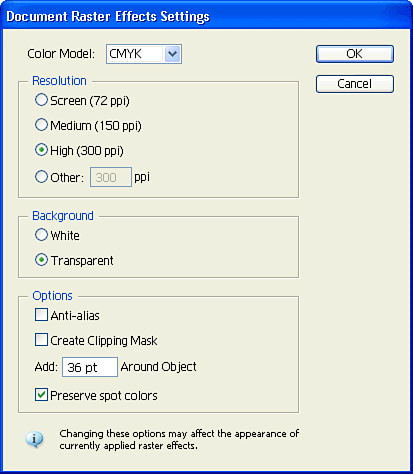
The thing to watch out for is that some effects, mainly the ones that fall in the lower half of the menu (what I call “below the line”), base their appearance on the resolution chosen. For example, the Pixelate effect bases its results on how many pixels there are. In that case, changing the document raster effects settings could change the appearance of any objects that have that effect applied. So it’s important to make any necessary adjustments to the Document Raster Effects Settings dialog box before you begin working on your design.
When you apply an effect, you can’t physically select it or work with it because it’s simply an appearance that’s applied to your object. However, sometimes you want to “break apart” an appearance so you can make adjustments or edits that the effect itself might not support. To do so, select the object with the effect applied to it, and choose Object, Expand Appearance.
After this function is applied, the effect no longer is live, and you can edit the actual final appearance of the object. If the object has several different effects applied or has multiple fills or strokes, the Expand Appearance function might create several overlapping objects.
Sometimes you want to distort an object using a specific shape. For example, you might want to squeeze some art into the shape of a circle. Although the Warp effect provides some simple distortion tools, it’s limited in that you can’t customize the distortions themselves. That’s where envelope distortion comes in. Almost similar to the way a mask works, you create a vector shape that will be the envelope. Then you place your art inside the envelope, but the result is that the art stretches or squeezes itself to conform to the shape (see Figure 7.146).
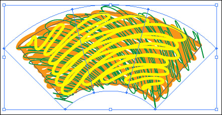
Illustrator can place any kind of art into an envelope, even raster image files. There are three ways to create envelopes in Illustrator:
Make with Warp—. Select the object you want to distort and choose Object, Envelope Distort, Make with Warp. You’re presented with a dialog box that looks similar in functionality to the Warp effect, except that when you click OK, you’ll notice that an envelope shape was created for you in the shape of the warp you specified (see Figure 7.147). You can use the Direct Selection tool to move each of those points individually. You can also use the Mesh tool to add more points for better control.
Make with Mesh—. Select the object you want to distort and choose Object, Envelope Distort, Make with Mesh. Specify how many rows and columns you want for your mesh (although you can always add more later with the Mesh tool) and click OK. Again, you can use the Direct Selection tool to move the mesh points, which distorts the art inside the envelope.
Make with Top Object—. Draw or select a shape you’d like to use as the envelope. Bring the shape to the front of the stacking order. Then add the art you want to distort to your selection, and choose Object, Envelope Distort, Make with Top Object.

As mentioned before, working with envelopes is similar in many ways to working with opacity masks. After you apply an envelope, you can access only the envelope itself, not the art that’s inside it. If you need to make a change to the art inside the envelope, select the envelope, and choose Object, Envelope Distort, Edit Contents (see Figure 7.148). You then can make changes to the art itself. When you’re done, remember to choose Object, Envelope Distort, Edit Envelope so you can work with the envelope again.

Illustrator has the capability to take two vector objects and create a blend between them. If the shapes are different, Illustrator morphs one shape into the other, which can produce some cool effects (see Figure 7.149). Blending can be used to create airbrushlike effects. Blends can also be used to help create steps or frames for animations, which can then be saved as Flash animations.

To create a blend, select two vector shapes and choose Object, Blend, Make. To change the options of a blend, select the blend and choose Object, Blend, Blend Options. You can specify a smooth colored blend, which automatically calculates how many steps are created in the blend, or you can choose to specify the exact number of steps you want to create (see Figure 7.150).

A blend follows along a straight path that is automatically drawn between the two objects (it doesn’t print), which is called the spine of the blend. If you want the blend to follow a specific curve (see Figure 7.151), select both the blend and the curve, and choose Object, Blend, Replace Spine.
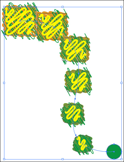
A blend in Illustrator is live, meaning that if you make changes to the two outer shapes, the blend updates accordingly. If you want to break a blend into its individual parts, choose Object, Blend, Expand.
You can place raster images into Illustrator to perform various tasks, including applying transformations (rotating, scaling, and so on), as well as using images in a mask.
Images in Illustrator can be either linked or embedded. Linking a file involves placing a reference to that file into your Illustrator file, but the image remains a separate file. If you want to make an edit to that image, you open the original file and change it. Upon saving the file, you return to using Illustrator. Because Illustrator maintains a link to that image, Illustrator knows that you’ve updated the image and asks whether you want the image to be updated in your layout. However, if you were to delete that linked image from your computer, Illustrator would not be capable of printing the file correctly.
Embedding an image is the process of permanently adding the image to the Illustrator file. Any changes you make to the original image will not be updated in your Illustrator layout. Embedding a file also increases the file size of your Illustrator document—significantly, if you’re embedding large high-resolution images.
You can choose to either link or embed your placed image at the time you place it. The Place dialog box contains a check box marked Link (which is on by default).
You can track and manage the use of linked images in your Illustrator documents by using the Links panel (found in the Window menu). If you want to edit a linked image, select the image in the Links panel (see Figure 7.152) and click on the Edit Original button at the lower right of the panel. Additionally, you can double-click on any of the items in the Links panel to get more information about that link.

If you place a Photoshop file that has layer comps into an Illustrator file (or if you choose to open a Photoshop file from Illustrator’s Open dialog box), you can specify which layer comp you want to appear when the image is placed. For more information on layer comps, refer to Chapter 6, “Using Adobe Photoshop CS3.”
Sometimes you want to convert raster images into vector objects. Whether you want to digitize a logo, draw a sketch by hand and then scan it, or turn a photo into something artistic, the Live Trace feature in Illustrator can make it easy to do.
Start by placing any raster-based file into your Illustrator document. When you’ve selected it, choose Object, Live Trace, Make or click Live Trace in the Control panel at the top of your window.
By default, Illustrator uses a simple black-and-white setting for tracing, but you can choose from Objects, Live Trace, Tracing Options or use the Tracing Options pop-up menu in the center of the Control panel to change the color (see Figure 7.153).
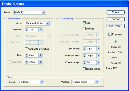
Live Trace objects maintain a link between the original raster image and the final traced vector result. You can always change between the Live Trace presets, or you can choose Object, Live Trace, Tracing Options to specify exact settings. Illustrator’s Live Trace feature actually performs some conditioning to the raster image before it traces it, allowing for better results. The left side of the Tracing Options dialog box contains settings for the raster conditioning. The right side of the dialog box contains settings that affect how the vector art is created.
To edit the actual vector paths of a traced object, you have to expand the Live Trace object first. With the Live Trace object selected, click on the Expand button in the Control panel. Alternatively, you can click on the Live Paint button to expand the traced art and convert it to a Live Paint group in one step, enabling you to easily fill the traced art with color using the Live Paint Bucket tool. When a Live Trace object is expanded, you can no longer change its trace settings.
The advantage of using Illustrator instead of a dedicated graph program to create graphs is that when you create a graph in Illustrator, it is made up of vector objects. Therefore, you can edit the graph just as you would any illustration, giving you complete control over the appearance of your graph or chart. If necessary, you can also export the graph in any of Illustrator’s many export formats, including the Save for Microsoft Office feature.
Illustrator can draw any of nine types of graphs: Column, Stacked Column, Bar, Stacked Bar, Line, Area, Scatter, Pie, and Radar.
To create a graph, choose one of the graph tools from the toolbox (see Figure 7.154). You start by first defining the area or size for your graph, and you specify this in much the same way that you do to create a rectangle. Either click and drag with the mouse, or click once on the artboard to enter a numeric value.

The next step is to give Illustrator the facts—the actual values that will be used to make the graph mean something. After it creates the bounding box for your graph, Illustrator presents you with the Graph Data panel. If you’ve ever used Microsoft Excel, this panel will look familiar to you. It is filled with rows and columns in which you enter the graph data (see Figure 7.155).

Across the top of the Graph Data panel are several items. The first is an area where you input your values. Select a cell (cells are the boxes that actually contain the data), and then type your value. Pressing Tab takes you to the next column; pressing Enter takes you to the next row.
You can either enter data manually or import data from Excel or any tab-delimited text file. Notice that in the upper-right corner of the Graph Data panel are six buttons. The following describes these buttons from left to right:
Import Data—. Imports data from an external file.
Transpose—. Switches columns and rows of data, no matter what the graph type is.
Switch X/Y—. Swaps the values of the x- and y-axes on a scatter graph only.
Cell Style—. Sets the parameters for a selected cell. You can set the number of decimal places as well as the column width.
Revert—. Sets the data in the graph back to the way it was before you last clicked the Apply button.
Apply—. Accepts and applies your changes to the graph.
What makes the graph function in Illustrator even more powerful is the capability to update the data in your graph. At any time, you can select the graph and choose Object, Graph, Data. You are presented with the Graph Data panel again, where you can update the numbers. When you click the Apply button in the Graph Data panel, the graph is automatically updated with the new information.
After you create your graph, you can edit it to perfection. Choose Object, Graph, Type, and you are presented with the Graph Type dialog box (see Figure 7.156). You are first presented with Graph Options. Here you can change the type of graph, even though you selected another type from the toolbox. You can also choose where you place the value axis.
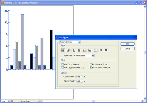
In addition to the options to add drop shadows or add a legend across the top, you can set the column width and cluster width here. These settings control the width and spacing of the bars or columns in a graph. Specifying a value greater than 100% causes the columns to overlap and can produce very unusual results.
In the Graph Type dialog box, you can also specify settings for the Value Axis and Category Axis. Select them from the pop-up menu at the top of the dialog box. In the Value Axis screen, you can set the length of tick marks, which are the lines along the side of the graph that help indicate the position of data. Setting tick marks at full length causes them to be drawn as lines throughout the entire graph. You can also specify tick marks for the Category Axis.
A graph is actually a special kind of group. You can ungroup a graph at any time—but be aware that when you do, the art loses its reference as a graph, and you can no longer make changes to it through the Graph Data panel and Graph Type dialog box. This process is similar to converting text to outlines: After you change it, it becomes a different kind of object. If you need to ungroup a graph, save a copy of the original grouped graph so you can go back to that stage, if needed.
Illustrator is a great tool for designing web graphics. Be it an entire site design, a navigation design, or a single graphic, the object-based properties of Illustrator graphics make it easy to create, design, and edit them. Additionally, because the graphics in Illustrator are resolution independent, you won’t need to re-create them at a higher resolution if you ever need to use the graphics for print purposes (something you might need to do if you use Photoshop).
When you’re designing for print, rarely are you ever concerned about pixels themselves. This is because image setters print at very high resolutions, such as 2400dpi or 3600dpi, and edges are always razor sharp. Even when you’re printing to lower-resolution devices, such as a 600dpi laser printer, the dots themselves are barely noticeable.
Web graphics are different, though, because images are rendered at the resolution of a computer monitor, which, in most cases, is 72 pixels per inch. To make graphics look prettier and smoother onscreen, a computer uses a method called antialiasing to slightly blur the contrasting edges of colors. The result is an image that looks clean and smooth instead of hard-edged and jagged (see Figure 7.157).
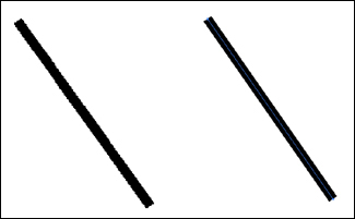
When you save or convert your graphic in a raster format, you can specify that Illustrator should apply antialiasing. However, when you’re viewing your graphic in Illustrator on the artboard, you also want to see what your graphic will look like with antialiasing applied. For that reason, Illustrator has a special preview mode called Pixel Preview, which you can find under the View menu. In Pixel Preview mode, your graphics display on your artboard as they would when viewed in a web browser. You can work and edit graphics in Pixel Preview mode, and you should do so when designing graphics for the Web.
Now, I know you’re probably thinking, “Why should I care what my image looks like when it’s antialiased?” The answer is that although antialiasing is generally a good thing, sometimes it can work against you. The side effect of blurring edges of color is that it sometimes makes your graphics illegible. This is especially true when your design contains small text or thin lines. Using Pixel Preview will help you see these issues before you export these graphics.
If you want to disable antialiasing for a single object, you can use the Rasterize live effect to do so. Make your selection and choose Effect, Rasterize. Choose 72ppi for the Resolution setting, choose None for the Antialiasing setting, and click OK. With Pixel Preview turned on, you can clearly see the difference.
As with many of the other applications in the CS3 suite, Illustrator has a Slice tool and a Slice Select tool for creating and selecting web slices, although it’s a bit different in Illustrator.
When you draw a slice with the Slice tool, Illustrator is really drawing a rectangle with no fill and no stroke, and making it a slice. When you want to edit the slice, you can use the Slice Select tool to change the boundaries of the slice.
However, Illustrator also has a different kind of slice. Instead of creating graphics and drawing slices over them, you can apply a slice as an attribute to a selection—something that Illustrator calls an object-based slice. To apply this kind of slice, make a selection and then choose Object, Slice, Make. Using this method, if you make an edit to your graphic, the slice updates automatically along with it.
After a slice is applied, you can choose Object, Slice, Slice Options to specify settings such as URL and ALT text. When you specify text as an object-based slice, you can also set the slice to be an HTML slice (rather than an image slice). In that case, Illustrator exports the text as editable HTML text instead of a graphic.
Illustrator allows you to prepare your finished artwork for deployment on the Web using the Save for Web and Devices option, which is virtually identical to the similarly named feature in Photoshop (see Chapter 6).
You can use Illustrator’s Save for Web feature to preview up to four optimized settings at once to help you choose the perfect web image, and you can find it by choosing File, Save for Web and Devices. You can also set different optimizations for your web slices and export graphics in GIF, JPEG, PNG, and WBMP formats.
Illustrator’s Save for Web and Devices feature does have two additional capabilities you won’t find in Photoshop, however: the capability to save in web vector formats and support for CSS layers.
Illustrator is a vector graphics application, so it only makes sense that Illustrator would support the vector graphics formats that are supported on the Web. Although the most popular graphics formats for Web use are raster based (GIF, JPEG, and PNG), two formats have become the Web standard for displaying vector-based graphics (see Figure 7.158): the Flash format (SWF) and the Scalable Vector Graphics format (SVG).

The Flash format has taken the Web by storm and has become the standard for creating interactive content—and even full websites—for the Web. The benefits of Flash are that you can animate content, add interactivity, add sound, and even script it with logic. To view SWF files in your web browser, you need to have a plug-in installed (a free download from Adobe’s website). Just about every web browser these days already comes with the Flash plug-in preinstalled.
For animation, the Flash format uses a frame-based model. Much like movies are made, each step of the animation is a separate frame. As each frame plays back, it gives the appearance of motion. For Illustrator specifically, you can use top-level layers as frames of an animation. The Save for Web and Devices dialog box gives you two options when saving a file in SWF format: AI File to SWF File, which saves your art as one static SWF file, and Layers to SWF Frames, in which your layers are converted to frames at export time and your SWF plays as an animation in a web browser or any Flash-capable browser.
You can also choose a frame rate (higher numbers make your animation play back faster, lower numbers make your animation play back slower). Setting your animation to loop makes it replay over and over again in your browser. Otherwise, it plays once and then stops.
If you have repeating objects in your design, you should define and use symbols because the Flash format supports the use of symbols to save file size. Remember that you can blend between symbols in Illustrator as well. Illustrations that are drawn using the symbolism tools are also exported to SWF as symbols. In fact, if you save your file in the SWF file format and then open that file in Flash, any symbols in your file become editable symbols in Flash as well.
The SVG format isn’t as widely used as the Flash format, but it has specific features that make it a better choice for certain kinds of graphics. SVG is an open standard file format based on XML and JavaScript. It supports animation, interactivity, and scripting. There’s no direct support for sound inside SVG, but you can use the SMIL standard to add sound to SVG graphics.
Because SVG is based on XML, which is also an open standard, SVG files are really just text files, meaning that they can be edited or changed very easily at any time. That opens SVG to a high level of customization functionality, including interaction with a database. For this reason, back-end developers and programmers lean toward SVG because it empowers them to use quality graphics but control and customize those graphics very easily. Many of the new cell phones that are available on the market today use SVG to display their graphics onscreen. SVG files that are created for display on cell phones usually conform to the SVG-Tiny standard. Other wireless devices, such as PDAs, utilize the SVG-Basic standard. Illustrator supports the export of both these formats.
Animation in SVG is timeline based. That means you specify an object to travel a set distance over a set amount of time (most video-based applications such as Adobe’s Premiere and After Effects and Apple’s Final Cut Pro use this method). Illustrator itself does not have a timeline, and there’s no way to specify SVG animation from within Illustrator. Most people who use Illustrator to create SVG graphics hand-code animation into their files after they have exported the file from Illustrator as an SVG file, or they use a third-party application.
SVG does support image slicing, as well as image maps that you can define using the Attributes panel. Any URLs you specify for an object inside Illustrator will export correctly in an SVG file.
Finally, Illustrator also provides variable support inside SVG files. We mentioned earlier that SVG is an open text-based file, allowing SVG to update graphics on the fly. Illustrator’s Variables panel (see Figure 7.159) enables you to define XML-based variables for text, linked images, and graphs, and to control visibility.

Increasingly, web designers and developers are seeing the benefits of using CSS layers in their web designs. Cascading Style Sheets (CSS) are a way to define how objects lay out on a web page. CSS enables designers to position graphics precisely, as well as overlap graphics. Developers also like CSS because of how efficient it can be when they’re creating large sites with many pages; it’s easy to make global changes using Cascading Style Sheets.
In Illustrator, you can export graphics from the Save for Web and Devices dialog box with CSS layers by clicking on the Layers tab and specifying which top-level layers you want to export (see Figure 7.160). You can also choose to export a layer as visible or hidden.
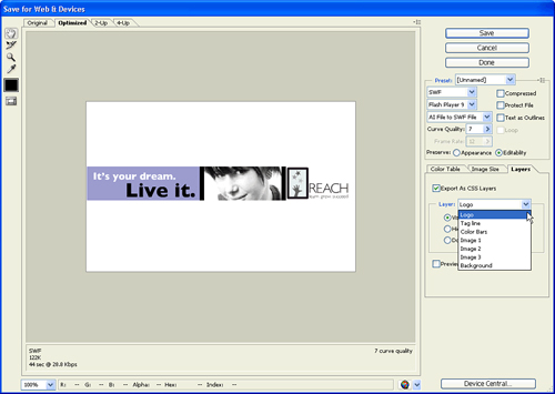
Illustrator can save files in various formats, each suited for different uses. Illustrator can also export files in a wide range of formats, which is one of the reasons some people consider Illustrator a valuable utility—even if they never actually draw anything with it.
Generally, Illustrator uses the Save command to save files that are “round-trippable,” meaning that those files can be reopened in Illustrator with no loss of editability. To save a file, choose File, Save; then from the pop-up menu, choose a format to save your file in (see Figure 7.161). If you want to save an existing file with different options, choose File, Save As.

In reality, Illustrator’s native file format is PDF—when you save a file as a native Illustrator file, you can open and view that file in Adobe Acrobat or in the Adobe Reader. This is also how InDesign is capable of placing native Illustrator files—because it reads the file as a PDF file.
You can choose from several options when saving an Illustrator file (see Figure 7.162):
Create PDF Compatible File—. As mentioned earlier, you can view a native Illustrator file in Adobe Acrobat because the Illustrator file is really a PDF file. However, this is true only when the Create PDF Compatible File option is checked when you save your file (it’s on by default). To significantly save file size, you could turn off this option, but be aware that other applications won’t be able to open the file correctly. For example, you won’t be able to place the file into InDesign. Uncheck this option only if you know that you will be only opening the file again in (and printing it from) Illustrator CS3 (the file won’t open in older versions of Illustrator, either).
Include Linked Files—. Check this option to include linked images inside the Illustrator file itself. This adds to your final file size but could allow Illustrator to print linked images if the link is broken or lost. To reopen the file in Illustrator, you’ll still need the linked images. If you have no linked images in your document, this option is grayed out.
Embed ICC Profiles—. If you have placed images that contain ICC color profiles into Illustrator, you can choose to embed those profiles using this option. If you have no images with ICC profiles in your document, this option is grayed out.
Use Compression—. Check this option (it’s on by default) to allow compression in the file to create a smaller file size.

You should save in the Illustrator format for the following:
Files that will be opened again in Illustrator CS3
Files that will be placed into InDesign 2.0 or later
Files that will be imported into an After Effects composition
EPS, which stands for Encapsulated PostScript, has been an industry-standard format since the industry of desktop publishing was created. The printing of EPS files requires a PostScript printer (or one that has a PostScript emulator). Because the EPS format has been around for so long, most applications that enable you to place art support the popular file format.
You can choose from several options when saving an Illustrator EPS file (see Figure 7.163):
Preview—. A PostScript file itself can’t be displayed on your screen (unless your computer screen understands PostScript), so a raster preview is included in the file as well. Macintosh previews (PICT files) won’t show up on a Windows computer, so if you’re planning to use your EPS on a Windows machine, choose a TIFF preview instead.
Transparency—. You have the option to either preserve or discard your overprint settings when saving an EPS file (some RIPs or trapping software prefer to handle overprint settings themselves). Additionally, if your document contains transparency, it requires flattening (PostScript doesn’t support transparency), and you can choose a transparency flattener style to use for that process.
Adobe PostScript—. If you’re printing to a PostScript Language Level 2 or 3 device, you can specify that here. By default, Language Level 2 is chosen, but you can change that to Language Level 3 if you have a printer that supports it, to take advantage of such things as smooth shading (which prevents banding in gradients).

You should save in the EPS format for the following:
Files that will be placed into QuarkXPress
Files that will be placed into various other applications that support the EPS format (video applications, 3D rendering programs, and so on)
Saving a file as an Illustrator template enables you to use that file as a document template on which to base other files. We discussed templates at the beginning of this chapter. There are no specific settings for saving a template file.
You should save files in the Illustrator template format if you want to use them as a template for future Illustrator documents.
One of the most popular formats chosen for saving files out of Illustrator is PDF. The PDF has become universally accepted around the world for viewing high-quality, graphically rich documents.
You can specify many different settings when saving a PDF file (see Figure 7.164):
Compatibility—. There are several versions of PDF to choose from in Illustrator. PDF 1.3 is the version of PDF that Acrobat 4 uses, and it does not support transparency (and requires flattening). PDF 1.4 is the version of PDF that Acrobat 5 uses, and it does support transparency (no flattening is required). PDF 1.5 is the version of PDF that Acrobat 6 uses, and it supports both transparency features and PDF layers. PDF 1.6 is the version of PDF that Acrobat 7 uses.
Preserve Illustrator Editing Capabilities—. This option (on by default) includes extra information in the file that allows Illustrator CS3 to reopen the PDF file and retain full editability. Turning off this option results in a significantly smaller PDF file, but it can result in lost information when the file is reopened in Illustrator. If you plan to turn off this option, I suggest keeping a copy of your original file for future editing.
Embed Page Thumbnails—. On by default, this option embeds raster thumbnails into the file, which some programs use to display PDF page previews.
Optimize for Fast Web View—. This option enables the PDF to start loading in a web browser as soon as it begins downloading, allowing viewers to see some contents of the PDF as they load rather than having to wait until the entire PDF is downloaded. This is similar in concept to interlacing.
View PDF After Saving—. If you’re sending your file to a client or a printer, you might want to open the file in Acrobat just to review it and make sure that it’s correct. Checking this option automatically opens the newly created PDF file in Acrobat as soon as you save it.
Create Acrobat Layers from Top-Level Layers—. When using the Acrobat 6 or Acrobat 8 compatibility setting, you can choose to export your top-level Illustrator layers as PDF layers (which can be viewed in either Acrobat 6 and higher or in the Adobe Reader).
Compression—. The PDF has full support for compression, and you can specify settings for different kinds of images. You can also specify the downsampling of images to create smaller PDF files (for onscreen viewing).
Marks and Bleeds—. If your file is going to a printer, you want to make sure that your final PDF has both bleed space and trim marks specified.
Security—. PDF files can be password protected on two levels. You can choose from these settings and also specify whether files can be printed at high resolution—or even printed at all.
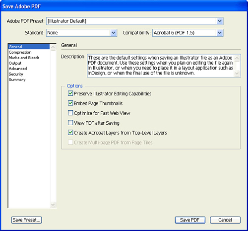
More detailed information on specific PDF settings can be found in Chapter 11, “Using Adobe Acrobat 8 Professional.” You should save in the PDF format for the following:
Files that will be opened in Adobe Acrobat or Adobe Reader
Files that will be sent to a client for review
Files that will be submitted to a printer for final processing
Files that will be submitted as ads for publications
As discussed earlier, SVG files are XML-based graphics files. Although you can export SVG files from the Save for Web and Devices feature, you can also save SVG files, which, by default, contain round-trip information to allow the files to be reopened in Illustrator with no loss in editability.
You can specify several settings when saving an SVG file (see Figure 7.165).

The Preserve Illustrator Editing Capabilities option (on by default) includes extra information in the file that allows Illustrator CS3 to reopen the SVG file and retain full editability. Turning off this option results in a significantly smaller SVG file, but it can result in lost information when the file is reopened in Illustrator. If you plan to turn off this option, I suggest keeping a copy of your original file for future editing.
SVGZ is a compressed SVG format that exhibits the same settings as SVG. You should save in the SVG format for the following:
Files that will be uploaded to a web page or wireless device
Files that will be used as templates for the Adobe Graphics Server
Files that will be sent to a web or back-end developer
When you export a file from Illustrator, you can expect to lose some editability if you want to reopen that exported file in Illustrator. To export a file, choose File, Export, and then choose a format in which to save your file from the pop-up menu.
Whenever you are exporting files from Illustrator, you always should save and keep a version of your file in case you need to make edits later.
The PNG (pronounced ping) format is a raster-based format. You might remember that you can export this format from the Save for Web and Devices function in Illustrator. However, the PNG format can also be used for non-Web applications. For example, you can place PNG files into Microsoft Word (which the Export for Microsoft Office feature uses). Using the PNG export feature enables you to export high-resolution files and specify certain features, such as interlacing and support for transparency.
By the same token, you can also save high-resolution JPEG images in RGB, CMYK, or Grayscale color modes via the Export feature in Illustrator.
Most people aren’t aware that you can actually save a Photoshop file from Illustrator. Instead of copying and pasting data from Illustrator to Photoshop, you can retain a lot more information by writing a Photoshop (.psd) file right from Illustrator. Features that are retained using this method are layers, layer names, nested layers, transparency blending modes, opacity levels, clipping masks, opacity masks, compound shapes, text, web slices, slice optimization settings, and image maps.
One of the challenges a designer faces is when a client asks for an image that he or she can place into a Microsoft Office application. With Illustrator CS3, you can use a feature called Save for Microsoft Office that creates a PNG file with one click of a button. Although PNG files are raster-based images, they are saved with a high enough resolution to look great both onscreen and on a printout.
If you require specific PNG settings, you can always use the PNG export option mentioned earlier.
To save a file for use in Microsoft Word, Excel, or PowerPoint, choose File, Save for Microsoft Office. When the file is created, you should use the Insert from File command in the Office application of choice to place the file.
To print a file, choose File, Print; you’re presented with the Print dialog box (see Figure 7.166). Along the left side of the dialog box is a list of different groups of options. The dialog box was designed so that most users don’t really have to go beyond the first group of options, though. Near the bottom of the dialog box is a Fit to Page option, which enables you to automatically enlarge or reduce your art to fill the paper size that’s chosen.

The lower left of the dialog box also contains a print preview window, which gives you a real-time representation of what your file will look like when it’s printed. You can click on the preview and drag it to reposition the art on the page, if you like.
Illustrator also lets you save all the Print dialog box’s settings as a print preset, which then appears for reuse in the Preset pop-up menu at the top of the dialog box.
If you’re like me, your head starts to hurt when you think about everything you can do in Illustrator. From drawing to text layout to charting and 3D rendering... this program can do it all. This chapter introduced you to many of the key features of Illustrator, but there is still more to learn! Be sure to take advantage of Bridge Home and the built-in help features of Illustrator to find out even more.