
TCP/IP is the standard set of protocols used in Internet communication. Our purpose in this chapter is not to write an exhaustive catalog of TCP/IP security. Rather, we lay the foundation for discussing more advanced topics later in the book, including operating system fingerprinting (Chapter 8) and intrusion detection systems (Chapter 19). In this chapter, we also briefly review attacks on and defense of TCP/IP, including fragmentation attacks and covert channels, and we examine emerging security and privacy issues with IPv6.
The Internet protocols, which are generally implemented on free, open source software, form the standard upon which Internet communication is based. The Transmission Control Protocol (TCP) and Internet Protocol (IP) are the two most important protocols for network security; we focus mainly on these in this chapter, although we also touch on several others.
The protocols were developed in the mid-1970s, when the Defense Advanced Research Projects Agency (DARPA) was working on a packet-switched network to enable communication between disparate computer systems at remote research institutions. TCP/IP was later integrated with Unix, and it has since grown into one of the fundamental communication standards of the Internet. The suggested readings at the end of this chapter reference some of the most relevant de facto standards documents (RFCs).
A TCP/IP packet is simply a package of data. Just like a mail package, the packet has both a source and a destination address, as well as information inside. Figure 6-1 gives a basic breakdown of a packet. Note that this is a generic representation of a packet. In practice, some fields are optional, some fields will be in a different order, and some other fields may be present as well. Each part of the packet has a specific purpose and is needed to ensure that information transfer is reliable.
Here’s how the data packet breaks down:
- Start indicator
Every message has a beginning; when you are writing a letter or email, you may start with “Hello”. The same rule applies to data transfer. When computers communicate, they send a stream of information. A start indicator designates when a new packet has begun.
- Source address
Every letter needs a reply address, and the source address provides it. Without a source address, a reply would be impossible.
- Destination address
Just as you would not open a letter addressed to your neighbor, a computer rejects any packets without the correct destination address.
- Control
This part of the data packet is used to send brief messages that let the receiving computer know more about the status of a communication. For example, just aswe generally say “Hello” at the beginning of a conversation, a computer uses this part of the packet to indicate the start of communication.
- Data
The only limitation on data is the size allowed to be sent in one packet. Each packet has a length, designated in bits. A bit is one of the eight units that make up a byte. A byte represents an alphanumeric value. For example, 00000011 is the same as the decimal number 3.
- Error control
Error handling is a significant aspect of any computing system: a computer program must be able to deal with anomalies. Whether it’s human error or machine corruption, a program must know when something is not right. Error control is arguably the most important part of the data packet, because it verifies the integrity of the rest of the data in the packet. Using checksums and other safeguards, error control ensures that the data arrives in its original form. If an error is found, the packet is rejected and the source address is used to request a new packet.
TCP is a connection-oriented protocol that provides reliable, stream-oriented connections in an IP environment. TCP corresponds to the transport layer (Layer 4) of the OSI reference model.
TCP guarantees delivery of packets to the application layer. This reliable delivery feature is based on sequence numbers that coordinate which data has been transmitted and received. TCP can retransmit any lost data. In addition, TCP senses network delay patterns and dynamically throttles data to prevent bottlenecks. Faster-sending hosts can be slowed down to let slower hosts catch up. TCP uses a number of control flags to manage the connection.
Features of TCP include the following:
- Stream data transfer
TCP delivers data as a continuous stream of bytes identified by sequence numbers. This saves time, since applications do not have to break data into smaller bits before sending. Instead, TCP groups bytes into segments and passes them to IP for delivery. The segments are later assembled at the destination according to the packet sequence numbers.
- Reliability
TCP ensures reliability by sequencing bytes with a forwarding acknowledgment number. Bytes that are not acknowledged within a specified time period are retransmitted.
- Efficient flow control
TCP provides efficient flow control: when sending acknowledgments back to the source, the receiving TCP process indicates the highest sequence number it can receive without overflowing its internal buffers.
- Full-duplex operation
Full-duplex operation allows TCP to both send and receive data at the same time.
The following descriptions summarize the TCP packet fields illustrated in Figure 6-2:
- Source port and destination port
Indicates the ports on the sending and receiving end of the connection
- Sequence number
Indicates the unique number assigned to the first byte of data in the segment
- Acknowledgment number
Provides the sequence number of the next byte of data expected on the receiving end
- Data offset
Indicates the number of 32-bit words in the TCP header
- Reserved
Reserved for future use
- Flags
Provide control markers such as the SYN, ACK, and FIN bits used for connection establishment and termination
- Window
Indicates the size of the receiving window (buffer) for incoming data
- Checksum
Verifies the integrity of received data
- Urgent pointer
Marks the start of urgent data
- Options
Includes numerous TCP options
- Data

IP is a network layer protocol that provides a connectionless service for the delivery of data. Since it is connectionless, IP is an unreliable protocol that does not guarantee the delivery of data. On the Internet, IP is the protocol used to carry data, but the actual delivery of the data is assured by transport layer protocols such as TCP.
IP headers contain 32-bit addresses that identify the sending and receiving hosts. Routers use these addresses to select the packet’s path through the network. IP spoofing is an attack that involves faking the return address in order to defeat authentication. That’s why you should not depend only on the validity of the source address when performing authentication.
IP packets may also be split (fragmented) into smaller packets, permitting a large packet to travel across a network that can only handle smaller packets. The Maximum Transmission Unit (MTU) defines the maximum packet size a specific network can support. IP then reassembles the fragmented packets on the receiving end. However, as we will see later, fragmentation attacks can be used to defeat firewalls under the right circumstances.
An IPv4 packet contains several types of information, as illustrated in Figure 6-3. IPv6 is discussed later in the chapter.

The following discussion describes the IP packet fields illustrated in Figure 6-3:
- Version
This is a four-bit field indicating the version of IP in use (in this case, IPv4).
- IP header length (IHL)
Specifies the header length in 32-bit (4-byte) words. This limits the maximum IPv4 header length to 60 bytes, which was one of the reasons for IPv6.
- Type-of-service
Assigns the level of importance and processing instructions for upper layers.
- Total length
Provides the length in bytes of the IP datagram (the data payload plus the IP header).
- Identification
A unique ID number that orders the data at the destination. This is a 16-bit number that is important in fragmentation.
- Flags
These are the fragmentation flags. These flags specify whether a packet can be fragmented and, if so, whether the packet is the last fragment of a packet sequence. Only two bits of this three-bit field are defined. The first bit is used to specify the “do not fragment” field. If this field is set, then the PMTU (Path MTU) is calculated, ensuring that all packets sent along the route are small enough to avoid fragmentation at MTU bottlenecks. The second bit indicates if the particular fragment is the last piece of the datagram or not.
- Fragment offset
Specifies the order of the particular fragment in the packet sequence.
- Time-to-live
Defines a counter to keep packets from looping endlessly. The host sets this field to a default value, and each router along the path decrements this field by one. When the value drops to one, the next router drops the packet. The process prevents infinite looping of forlorn packets.
- Protocol
This eight-bit field defines the protocol that will receive the packet from the IP layer.
- Header checksum
This field checks for IP header integrity. Note that this is not a cryptographic checksum and can be easily forged.
- Source address
This 32-bit field specifies the sender’s address.
- Destination address
This 32-bit field specifies the receiver’s address.
- Options
Specifies various options.
- Data
Unlike TCP, the User Datagram Protocol (UDP) specifies connectionless datagrams that may be dropped before reaching their targets. In this way, UDP packets are similar to IP packets. UDP is useful when you do not care about maintaining 0% packet loss. UDP is faster than TCP, but less reliable. Unfortunately, UDP packets are much easier for an attacker to spoof than TCP packets, since UDP is a connectionless protocol (i.e., it has no handshaking or sequence numbers).
Internet Control Message Protocol (ICMP) is a testing and debugging protocol that runs on top of a network protocol. Normally, routers use ICMP to determine whether a remote host is reachable. If there is no path to a remote host, the router sends an ICMP message back stating this fact. The ping command is based on this feature. If ICMP is disabled, then packets are dropped without notification, and it becomes very difficult to monitor a network.
ICMP is also used in determining the PMTU. For example, if a router needs to fragment a packet (as described below), but the “do not fragment” flag is set, the router sends an ICMP response so the host can generate packets that are smaller than the MTU.
ICMP is also used to prevent network congestion. For example, when a router buffers too many packets due to a bottleneck, ICMP source quench messages may be generated. Although rarely seen in practice, these messages would direct the host to slow its rate of transmission. In addition, ICMP announces timeouts. If an IP packet’s time-to-live (TTL) field drops to zero, the router discarding the packet can generate an ICMP packet announcing this fact. Traceroute is a tool that maps network routes by sending packets with small TTL values and watching the ICMP timeout announcements.
Unfortunately, ICMP is a frequently abused protocol. Unchecked, it can allow attackers to create alternate paths to a target. As a result, some network administrators configure their firewalls to drop ICMP messages. However, this solution is not recommended, as Path MTU relies on ICMP messages: without ICMP enabled, large packets can be dropped, and the problem will be difficult to diagnose. Note that many firewalls provide you enough granularity to drop particular ICMP types that may be frequently abused.
The Address Resolution Protocol (ARP) enables hosts to convert a 32-bit IP address into a 48-bit Ethernet address (the MAC or “network card” address). ARP broadcasts a packet to all hosts attached to an Ethernet. The packet contains the desired destination IP address. Ideally, most hosts ignore the packet. Only the target machine with the correct IP address named in the packet should return an answer.
ARP spoofing is an attack that occurs when compromised nodes have access to the local area network. Such a compromised machine can emit phony ARP replies in order to mimic a trusted machine.
(RARP) is the reverse of ARP. RARP allows a host to discover its IP address. In RARP, the host broadcasts its physical address and a RARP server replies with the host’s IP address.
The Bootstrap Protocol (BOOTP) allows diskless network clients to learn their IP addresses and the locations of their boot files and boots. BOOTP requests and replies are forwarded at the application level (via UDP), not at the network level. Thus, their IP headers change as the packets are forwarded. The network client broadcasts the request in a UDP packet to the routers. The routers then forward the packets to BOOTP servers.
The Dynamic Host Configuration Protocol (DHCP) is an extension of BOOTP and is also built on the client/server model. DHCP provides a method for dynamically assigning IP addresses and configuration parameters to other IP hosts or clients in an IP network. DHCP allows a host to automatically allocate reusable IP addresses and additional configuration parameters for client operation. DHCP enables clients to obtain an IP address for a fixed length of time, which is known as the lease period . When the lease period expires, the remote DHCP server can assign the IP address to another client on the network.
As described above, the control segment determines the purpose of the packet. Using this segment, remote hosts can set up a communication session and disconnect the session. This part of the communication process is called the handshake. When an information path is opened between computers, the path stays open until it receives a “close” signal. Although the resources used for the session will return to the computer after a period of time, without a close signal those resources are needlessly tied up for several minutes. If enough dead connections are set up, a host becomes useless. This situation is the basis for certain denial-of-service attacks.
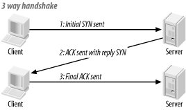
When a server receives a packet from the Internet, it inspects the control segment to see the purpose of the packet. In order for a session to initialize, the first packet sent to a server must contain a SYN (synchronize) command. The command is received by the server and resets the sequence number to 0. The sequence number is important in TCP/IP communication because it keeps the packet numbers equal. If a number is missing, the server knows that a packet is missing and requests a resend.
Once the SYN number is initialized, an acknowledgment (ACK) is sent back to the client that is requesting a session. Along with the ACK, a responding SYN is sent in order to initialize the sequence number on the client side. When the client receives the ACK and SYN, it sends an acknowledgment of receipt back to the server, and the session is set up. This example is an oversimplification, but it illustrates the basic idea of a three-way handshake (see Figure 6-4).
When a session is over and the client is finished requesting information from the server, it says goodbye. To disconnect, the client sends a FIN (final command) to the server. The server receives the FIN and sends its own FIN with an ACK to acknowledge that the session is terminated. The client sends one final ACK to confirm the termination, and the client and server separate. During the connecting and disconnecting handshakes, the client and server are constantly sending packets of information with sequence numbers.
Attackers can abuse the TCP/IP handshake. For example, a TCP SYN attack generates SYN packets with random source addresses and launches them at a victim host. The victim replies to this random source address with a SYN ACK and adds an entry to the connection queue. However, since the SYN ACK is destined for a phantom host, the final step of the handshake is never completed. Thus, the connection is held open for a minute or so. Unfortunately, a flood of such spoofed packets can result in a denial-of-service condition when the target host’s connection resources are overwhelmed. Worse, it is difficult to trace the attacker to his origin, as the IP address of the source is a forgery. For a public server (e.g., a web server), there is no perfect defense against such an attack. Possible countermeasures include increasing the size of the connection queue, decreasing the timeout, and installing vendor software patches to help mitigate such attacks. SYN cookies are also very effective, and there are methods to prevent your hosts from becoming relays (zombies) for attacks. The SYN flood attack relies on random IP source address traffic; thus, it is important to filter outbound traffic to the Internet.
It’s possible to abuse the various fields in TCP and IP headers to transmit hidden data. For example, an attacker encodes ASCII values ranging from 0-255 into the IP packet identification field, TCP initial sequence number field, etc. How much data can be passed? To give an example, the destination or source port is a 16-bit value (ports range from 0 to 65535, which is 2^16-1), while the sequence number is a full 32-bit field.
Using covert channels — hiding data in packet headers — allows the attacker to secretly pass data between hosts. This secret data can be further obfuscated by adding forged source and destination IP addresses and even by encrypting the data. Furthermore, by using fields in TCP/IP headers that are optional or unused, the attacker can fool intrusion detection systems.
For instance, TCP, IP, and UDP headers contain fields that are undefined (TOS/ECN), unset (padding), set to random values (initial sequence number), set to varied values (IP ID), or optional (options flag). By carefully exploiting these fields, an attacker can generate packets that do not appear to be anomalous—thus bypassing many intrusion detection systems.
When a new TCP connection is established, the sender automatically generates a random initial sequence number. An attacker could encode part of a message — up to 32 bits of information — in the initial sequence number. It is difficult to detect and prevent such a covert channel, unless the connection passes through an application-level proxy (such as a good proxy firewall or other device) that disrupts the original TCP session.
As described above, IPv4 limits address space to 32 bits. Unfortunately, 32 bits proved a severe limitation on the rapid expansion of Internet addresses, so the IETF began work on the next generation, known as IPv6. IPv6 increases the address space to 128 bits, or 16 bytes.
IPv6 does not provide fragmentation support for transit packets in routers. The terminal hosts are required to perform PMTU to avoid fragmentation. In addition, IPv6 has enhanced options support. The options are defined in separate headers, instead of being a field in the IP header. Known as header chaining , this format inserts the IP option headers between the IP header and the transport header.
The IPv6 header fields (shown in Figure 6-5) can be described as follows:
- Version
A four-bit field describing the IP version (in this case, IPv6).
- Traffic class
Similar to the Type-of-Service field in IPv4.
- Flow label
This experimental 20-bit field is under development to signal special processing in routers.
- Payload length
This 16-bit field indicates the length of the data payload.
- Next header
This is similar to the Protocol field in the IPv4 header, but it also includes the Options header.
- Hop limit
This eight-bit field serves a purpose similar to the TTL field in the IPv4 header.
- Source and destination address
128-bit fields that represent the source and destination addresses in IPv6 format.
- Data
Includes the information payload.

IPv6 has an updated addressing scheme that accommodates the geometric expansion of the Internet. IPv4 used decimal notation to represent a 32-bit address, such as 255.255.255.0. In contrast, IPv6 uses hexadecimal numbers, separated by colons. An example of this would be as follows:
1844:3FFE:B00:1:4389:EEDF:45AB:1029
One growth area of IPv6 is expected to be in wireless devices such as cellular phones and PDAs, which benefit from the enlarged address space. However, some experts have raised privacy concerns. For example, the IPv6 address space in some cases uses a unique identifier (ID) derived from your hardware (e.g., handheld phone) that allows packets to be traced back to your device. This can be a problem: the IPv6 ID can also be used to determine the manufacturer, make, model number, and value of the hardware equipment being used.
As a workaround, the IETF published RFC 3041, “Privacy Extensions for Stateless Address Autoconfiguration in IPv6.” The RFC describes an algorithm to generate randomized interface identifiers and temporary addressees during a user session.
It is useful to understand how a packet is constructed at the byte level (discussed below), but for practical purposes, tools such as Ethereal make packet analysis much easier. Ethereal (http://www.ethereal.com) performs packet sniffing on almost any platform, in real time and on saved capture files from other sniffers (NAIs Sniffer, NetXray, tcpdump, Airscanner Mobile Sniffer, and more). Many features are included with this program, such as filtering, TCP stream reconstruction, promiscuous mode, third-party plug-in options, and the ability to recognize more than 260 protocols. Ethereal also supports capturing on Ethernet, FDDI, PPP, Token Ring, X-25, and IP over ATM. In short, it is one of the most powerful sniffers available—and it is free. Supported platforms include Linux (Red Hat, SuSE, Slackware, Mandrake), BSD (Free, Net, Open), Windows (9x/ME, NT4/2000/XP), AIX, Compaq Tru64, HP-UX, Irix, MacOS X, SCO, and Solaris.
Installation varies, depending on the platform. Because 98% of people using Ethereal employ a Linux distribution (such as RedHat) or a Windows operating system, we discuss only those platforms. For the most part, what works on one *nix operating system will work on another, with only slight modifications to the installation procedure.
Once Ethereal is loaded, it will present a three-paned screen. Each of the panes serves a unique purpose, and they present the following information.
- Packet summary
This is a list of all the captured packets, including the packet number (1-65, 535), timestamp, source and destination addresses, protocol, and some brief information about the data in the packet.
- Packet detail
This window contains more detailed information about the packet, such as MAC addresses, IP address, packet header information, packet size, packet type, and more. This is useful when you are interested in what type of data a packet contain, but you don’t care about the actual data. For example, if you are troubleshooting a network, you can use this information to narrow down possible problems.
- Packet dump (hex and ASCII)
This field contains the standard three columns of information found in most sniffers. On the left is the memory value of the packet; the middle contains the data in hex, and the right contains the ASCII equivalent of the hex data. This is the section that lets you actually peer into the packet, and see what type of data is being transmitted, character by character.
In this section, we examine a sample packet as captured by a sniffer. It is important to understand how to edit packets at the byte level so that you can understand how fragmentation attacks work. Figure 6-6 shows the hex dump of a sample packet that we have captured.

We will focus on the first 54 bytes, which comprise the frame header (14 bytes), the IP header (20 bytes), and the protocol header (20 bytes), as seen here:
00 10 67 00 B1 DA 00 50 BA 42 E7 70 08 00 45 00 01 66 F4 19 40 00 80 06 BA 77 D0 BE 2A 09 40
        1D 10 1C 08 CB 00 50 20 14 12 6A 49 E6 C5 36 50 18 44 70 37 0B 00 00
Scanning from left to right, we read the first 14 bytes; they
comprise the frame header, which in this packet provides us with the
source MAC address (00 10 67 00
B1 DA) and the destination MAC
address (00 50 BA 42 E7 70). The
final 08 00 marks the beginning of
the IP datagram.
The next 20 bytes comprise the IP header, as shown here:
45 00 01 66 F4 19 40 00 80 06 BA 77 D0 BE 2A 09 40 1D 10 1C
At the end of this header are the source IP address (D0 BE 2A 09) and the destination IP address
(40 1D 10 1C).
Converting the destination IP address to decimal gives us the following:
40 1D 10 1C = 64.29.16.28
which is the IP address that resolves to the URL http://www.virusmd.com.
The final 20 bytes form the TCP header, shown here:
08 CB 00 50 20 14 12 6A 49 E6 C5 36 50 18 44 70 37 0B 00 00
This section contains the following information:
Source port
Destination port (
00 50 = 80 = http:// port)Sequence number
Acknowledgment number
Header length
TCP flags
These are the TCP flags:
- URG
Indicates that the packet contains important data
- ACK
Provides an acknowledgment of the last packet (all packets except the first have this set)
- PSH
Sends immediately, even if the buffer isn’t full
- RST
Resets the connection (an error occurred)
- SYN
Starts a connection
- FIN
Closes a connection
Fragmentation is a normal event in which packets are split into bite-sized pieces, either at the packets’ origin or at the routers. The packets are later reassembled at their destination. Fragmentation allows packets to traverse networks whose maximum packet size (MTU) is smaller the packet itself. For example, packets traveling over Ethernet cannot exceed 1,518 bytes. Thus, the IP layer payload must be less than or equal to 1,480 bytes:
1480 byte transport payload
+ 20 byte IP header
+ 14 byte Ethernet layer header
+ 4 byte checksum
= 1518 bytes
The IP layer is responsible for reassembling the fragmented packets at the destination. It then passes the payload up to the transport layer. The IP header stores valuable information that allows the packets to be reassembled in the correct order at their destination.
The fragmentation variables stored in the IP header include the following:
- Fragment ID
This is the same as the unique IP identification number of the parent packet. The fragment ID remains the same in all progeny of a packet, even if the fragments are themselves fragmented into smaller bits by networks with low MTUs.
- Fragment offset
Each fragment marks its place in the packet’s sequence of data with a fragment offset. At the destination, this number is used to reassemble the fragments in the correct order.
- Fragment length
Each fragment contains a field describing its own total length.
- More fragments flag
A fragment must tell whether there are any more fragments that follow in the fragmentation sequence. This flag can be equal to one (1), meaning that there are more fragments to follow, or to zero (0), meaning that it is the final fragment in the packet.
Fragmentation is a normal event. However, as with all technology, crackers can exploit fragmentation for their own purposes. By handcrafting fragmented packets, attackers attempt to avoid detection when performing reconnaissance and penetration.
For example, clever fragmentation can often be used to avoid intrusion detection systems or IDSs (see Chapter 19). Recall that all fragments of a packet must contain a copy of the parent packet’s IP header. However, only the first fragment contains a protocol header such as TCP, ICMP, or UDP. Thus, less sophisticated IDSs that screen the protocol header cannot block later fragments of a malicious packet.
Another kind of attack uses fragmentation to perform a denial-of-service (DoS); it is the classic ping of death. This attack uses the system ping utility to create an IP packet that exceeds the maximum allowable size of 65,535 bytes for an IP datagram. The attack launches a swarm of small, fragmented ICMP packets. These fragments are later reassembled at the destination, at which point their massive size can crash the target.
Although the ping of death is an old attack, efforts to protect against it have led to even more problems. For example, in order to identify and audit such attacks, Checkpoint added a logging mechanism to Firewall-1 to record the fragment reassembly process. Unfortunately, as Lance Spitzner discovered, the auditing process itself can cause a denial-of-service condition on the firewall. It’s possible for an attacker to send a number of incomplete fragments to the firewall that can never be reassembled. This causes the CPU utilization to rise toward 100%, thus freezing the firewall.
Nmap (Network Mapper) is a network reconnaissance tool discussed in Chapter 9. It was written by Fyodor of Insecure.org (Fyodor was also a technical reviewer for this book). One of its more obscure options is its ability to generate fragmented packets. Nmap allows you to use raw IP packets to perform reconnaissance on the hosts available on a target network, the services (ports) open, the operating system (and version) running, the type of packet filters/firewalls in use, and dozens of other characteristics. Nmap is available on both Linux and Windows.
Nmap has the ability to craft and fragmented packet launch
them at a host. Using the -f
(fragment) option, you can
perform a scan using fragmented IP packets. In fragment mode, Nmap
splits the TCP header over several packets in order to make it more
difficult for packet filters and IDSs to detect the scan.
Although this method will not fool firewalls that maintain packet sequence state (discussed above), many networks cannot handle the performance overhead of tracking fragments, and thus do not maintain state.
Salvatore Sanfilippo designed hping (http://www.hping.org) as a command-line TCP/IP packet assembler/analyzer based on the original Unix ping command. However, hping isn’t just able to send ICMP echo requests. It also supports the TCP, UDP, ICMP, and RAW-IP protocols, and it includes a traceroute mode, the ability to send files between a covert channel, and many other features.
Uses of hping include the following:
Firewall testing
Advanced port scanning
Network testing using different protocols, TOS, and fragmentation
Manual PMTU discovery
Advanced traceroute, under all the supported protocols
Remote OS fingerprinting
Remote uptime guessing
TCP/IP stack auditing
Supported platforms include Linux, FreeBSD, NetBSD, OpenBSD, and Solaris. It produces a standard TCP output format, as follows:
len=46 ip=192.168.1.1
flags=RA DF seq=0 ttl=255 id=0 win=0 rtt=0.4 ms
This breaks down as follows:
- len
The size, in bytes, of the data captured from the data link layer, excluding the data link header size. This may not match the IP datagram size, due to low-level transport layer padding.
- ip
The source IP address.
- flags
The TCP flags: R for RESET, S for SYN, A for ACK, F for FIN, P for PUSH, U for URGENT, X for not standard 0x40, Y for not standard 0x80.
- DF
If the reply contains DF, the IP header has the “don’t fragment” bit set.
- seq
The sequence number of the packet, obtained using the source port for TCP/UDP packets or the sequence field for ICMP packets.
- ttl
The IP Time-to-live field.
- id
The IP ID field.
- win
The TCP window size.
- rtt
The round-trip time in milliseconds.
If you run hping using the -V command-line switch, it will display
additional information about the packet. For example:
len=46 ip=192.168.1.1 flags=RA DF seq=0 ttl=255 id=0 win=0 rtt=0.4 ms tos=0 iplen=40
seq=0 ack=1223672061 sum=e61d urp=0
Here’s how it breaks down:
- tos
The Type-of-Service field in the IP header
- iplen
The IP total len field
- seq and ack
The 32-bit numbers sequence and acknowledge in the TCP header
- sum
The TCP header checksum value
- urp
The TCP urgent pointer value
One of the most useful tools for generating fragmented packets is Fragroute (http://www.monkey.org/~dugsong/fragroute/). According to its author Dug Song, Fragroute is a Unix-based tool that intercepts, modifies, and rewrites egress traffic destined for a specified host. It includes a rule-based language to “delay, duplicate, drop, fragment, overlap, print, reorder, segment, source-route, or otherwise monkey with all outbound packets destined for a target host, with minimal support for randomized or probabilistic behavior.” The author claims to have written the tool for good, not evil, in order to aid in the testing of network intrusion detection systems, firewalls, and basic TCP/IP stack behavior. Examples of ways to use Fragroute for testing include the following:
Testing network IDS timeout and reassembly
Testing stateful firewall inspection
Simulating one-way latency, loss, reordering, and retransmissions
Evading passive OS fingerprinting techniques
For example, Fragroute can generate enough “noise” in the form of complex packet fragments that it will overwhelm or evade an IDS’s ability to maintain state.
The syntax for Fragroute is as follows:
fragroute [-f file] host
The -f option allows you to
read the ruleset from a specified file, instead of
/usr/local/etc/fragroute.conf.
Fragroute is composed of several modules that enable various configuration directives. Each directive operates on a logical packet queue handed to it by the previous rule. Examples of its ruleset include the following:
delay first|last|random
              ms
Delay the delivery of the first, last, or a randomly selected packet from the queue by
msmilliseconds.drop first|last|random prob-%Drop the first, last, or a randomly selected packet from the queue with a probability of
prob-%percent.dup first|last|random prob-%Duplicate the first, last, or a randomly selected packet from the queue with a probability of
prob-%percent.ip_chaff dup|opt|ttlInterleave IP packets in the queue with duplicate IP packets containing different payloads, either scheduled for later delivery, carrying invalid IP options, or bearing short time-to-live values.
ip_frag size
              [old|new]
Fragment each packet in the queue into
size-byte IP fragments, preserving the complete transport header in the first fragment. An optional fragment overlap may be specified as old or new, to favor newer or older data.ip_opt lsrr|ssrr ptr ip-addrAdd IP options to every packet in order to enable loose or strict source routing. The route should be specified as a list of IP addresses and a bytewise pointer into them (e.g., the minimum
ptrvalue is 4).ip_ttl ttlSet the IP time-to-live value of every packet to
ttl.ip_tos tosSet the IP type-of-service bits for every packet to
tos.order random|reverseReorder the packets in the queue randomly, or in reverse.
tcp_chaff
              cksum|null|paws|rexmit|seq|syn|ttl
Interleave TCP segments in the queue with duplicate TCP segments containing different payloads, either bearing invalid TCP checksums, null TCP control flags, older TCP timestamp options for PAWS elimination, faked retransmits scheduled for later delivery, out-of-window sequence numbers, requests to re-synchronize sequence numbers mid-stream, or short time-to-live values.
tcp_opt mss|wscale
              size
Add TCP options to every TCP packet in order to set the maximum segment size or window scaling factor.
tcp_seg size
              [old|new]
Segment each TCP data segment in the queue into
size-byte TCP segments. Optional segment overlap may be specified as old or new, to favor newer or older data.
For example, if you wanted to fragment all traffic to a Windows host into forward-overlapping eight-byte fragments (favoring older data), reordered randomly and printed to standard output, you would perform the following:
ip_frag 8 old
order random
print
Fragroute has been successfully used to confuse Snort and other IDSs by generating confusing packet fragments.
“A Security Review of Protocols: Lower Layers,"by S.M. Bellovin, et al. (http://www.InformIT.com)
“Security Problems in the TCP/IP Protocol Suite,” by S.M. Bellovin. Computer Communication Review, Vol. 19, No. 2, pp. 32-48. April 1989
“Overcoming IPv6 Security Threat,” by Joe Baptista. (http://www.circleid.com)
“An Analysis of Fragmentation Attacks,” by Jason Anderson. (http://www.sans.org)
“Defining Strategies to Protect Against TCP SYN Denial of Service Attacks.” (http://www.cisco.com)
“IP-Spoofing Demystified.” daemon9 / route / infinity. (http://www.phrack.org)
RFC 768. “User Datagram Protocol,” August 1980.
RFC 791. “Internet Protocol, DARPA Internet Program, Protocol Specification,” September 1981.
RFC 792. “Internet Control Message Protocol, DARPA Internet Program, Protocol Specification,” September 1981.
RFC 793. “Transmission Control Protocol, DARPA Internet Program, Protocol Specification,” September 1981.
RFC 826. “An Ethernet Address Resolution Protocol,” November 1982.
RFC 951. “Bootstrap Protocol (BOOTP),” September 1985.
“Covert channels in the TCP/IP protocol suite,” by Craig H. Rowland. (http://www.firstmonday.dk/issues/issue2_5/rowland/)
“Syn Cookies,” by D. J. Bernstein. (http://cr.yp.to/syncookies.html)
RFC 3041. “Privacy Extensions for Stateless Address Autoconfiguration in IPv6,” January 2001.
Airscanner Mobile Sniffer User’s Manual, by Seth Fogie and Cyrus Peikari. (http://www.airscanner.com)
Internet Core Protocols: The Definitive Reference, by Eric A. Hall. O’Reilly, 2000.
“How does Fragroute evade NIDS detection?” by Michael Holstein. (http://www.sans.org)