
3.11 Sketching with Foam Core
sketching in a physical medium
Most people think of sketching as something done with paper and pen (or digital equivalents). Yet sketching can also be done by creating physical mock-ups of devices and situations. Architects do this when they create scale models of buildings and their surrounds. Industrial designers do this by crafting models of their devices out of clay. Some interaction designers also construct interactive scale models of devices, often using foam core sheets and other everyday materials (such as cardboard) as their medium. Unlike a paper sketch that represents a device, you can have others actually ‘operate’ your physical device.
In this chapter, you will learn how to build simple mockups of physical devices by using few layers of foam core sheets. You will see that you can use this approach to rebuild and extend low fidelity imitations of existing devices, and to realize a physical design of device that may exist only in your imagination.
Method 1: Sketching a Novel Interface for a Digital Watch
We will introduce you to foam core by having you build a foam core model of a digital armband watch that includes a touch screen interface. The result will be an arm wearing the watch, where one can change what the watch displays by sliding a strip of paper underneath the display that contains a storyboard of the watch’s screens (see image at end).
1. Take a photo of a person’s arm, and create a photo trace sketch as described in Chapter 3.9.
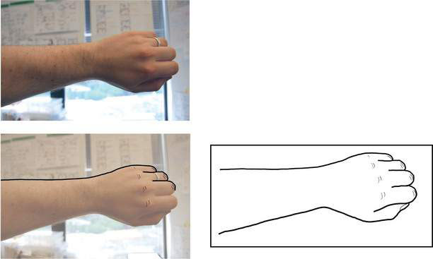
2. Sketch an armband watch over this sketch trace. Make the watch display fairly large, as you will be illustrating screens within it later.

3. Print the sketch at the correct scale, i.e., so that the hand and arm are life-size. You can usually do this by manipulating the scale settings in your application’s print settings or your computer’s print dialog box.
4. Glue the printed sketch onto one of the foam core sheets.

5. Cut out a rectangular area around the sketch.

6. Cut a second piece of the foam core sheet so it is the same size as the sheet containing the arm.

Then cut two thinner strips of the same length and set them aside. We will use these shortly to create a ‘tray’ underneath the arm that holds a storyboard.
7. Cut out the center area of the display.

8. Create the foam core tray. This will allow you to slide a storyboard under the watch display. First, glue two strips at the sides of the rectangular cut out. Then glue that assembly to the underside of the watch. This will create a hollow channel under the arm.

9. The next step is to sketch out a storyboard sequence (Chapter 4.1), where the storyboard displays a sequence of sketches that will appear in the the cut-out square that comprises the watch display. First, cut out long strips of paper the same width as the channel in the foam core model (you can glue several shorter strip together to make a long strip; the longer the strip, the more space for screens in your storyboard). The idea is to slide this piece of paper into the channel, where each storyboard screen will appear under the watch display.

10. Slide this paper strip into the model and use a pencil to draw outlines of the display onto the paper strip. After each drawn rectangle, slide the paper strip further until the just drawn rectangle disappears. Continue until you have a series of rectangles on the paper.

11. Using one or more of the techniques learned in earlier chapters, sketch the storyboard as a series of graphical user interface screens that fit within these boxes. Chapter 4.1 will discuss storyboards in more detail.
12. The foam core and paper prototype of our touch-screen watch is now finished. Demonstrate interaction with the watch to another person by sliding through a sequence of user interface stages on the paper strips. You can even have them ‘touch’ the appropriate control before moving to the next screen.

13. Instead of sketching each screen by hand, you can also print out screens created digitally; the only constraint is that the screen size must fit the size of the cut-out. For example, the image below illustrates screens created for a user interface sequence discussed in the next section of this book (Chapters 4.1 – 4.3).

14. As an exercise, create multiple storyboards, each showing a different aspect of the watch, or a different scenario of use, or perhaps even a different way of interacting with the watch. For example, use the same foam core model (but different storyboards) to create a watch that responds to single touch, to multi-touch, and to voice input.
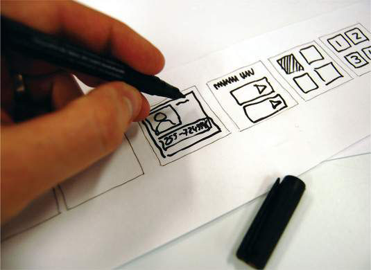
The foam core model below is a prototype of a hand-held device. Unlike our above example that is mounted on a foam core ‘arm’, the device is used directly.

The buttons on the device as well as the sketches were produced digitally, giving the prototype a much more realistic ‘final’ appearance. This is appropriate for a sketch far down in the design funnel.
The image illustrates a project by Sue-Tze Tan from the Department of Industrial Design, University of Washington, and is reproduced from Bill Buxton’s Sketching The User Experience.
Method 2: Using Photos to Prototype Existing Devices
Many interaction designs involve legacy devices, where the interaction designer has to build an interface that works within the constraints of an existing device, such as a smart phone or a tablet computer. Somewhat similar to the technique shown above, you can build simple mockups of existing devices out of foam core. The idea is to paste photos of such devices atop the foam core. This gives your model a realistic appearance and size (the front layer). As in the previous example, you then create a back and middle layer to hold the screens you design.
1. Begin with a front- facing photo of the device you are interested in. Our example uses a specific mobile phone. If it’s a popular device, you will likely find a suitable photo by searching the web. Otherwise, take a photo of its front side, as we did below.

2. Print out the photo of the device. Make sure to use the right printing scale factor to make it life-size.

3. Glue the photo atop one of the foam core sheets.
4. Cut around the phone’s outline so only the photo surface is visible.

5. Cut out the opening that you want to use as displays (e.g., the center area of the phone).

6. Create the phone’s back and middle layer.
For the back layer, cut some foam core the same size as the front layer.
For the middle layer, cut foam core the same size as the front layer, but also cut into it a U-shaped space that will create a ‘foam core sandwich’ that holds the displays.

7. Glue the foam core pieces together: back layer, middle layer, and front layer.

8. This particular foam core model only holds one screen at a time. Consequently, create sketches of each screen on small pieces of stiff paper (e.g., cut from index cards), each ordered in a sequence. Cut the sheets of paper in the same width as our opening of the foam core model. Make the height of these cards a little bit longer so that a 1–2 cm part of the paper comes out of the foam core model once we put the sketches inside. This way it is easier to grab each page and slide it out of the device once you go through your interaction sequence later.
9. To demonstrate interaction with this device, put the paper cards with the interface sketches inside the foam core model. Then take out one card after another.

10. To illustrate a sequence, slide the paper into the middle section of the foam core sandwich. Have the ‘user’ perform an action, then remove that sheet and replace it with the appropriate next screen.

The strips in the first example are convenient and provide a smooth demonstration, as you just have to slide the strip in the tray. However, it is limited to show a strict sequential sequence (see Chapter 4.1). The individual cards in the second example are less convenient to show and display, but are far more flexible. The next screen can be one of several available, where the one chosen and slid into the foam core model depends on the user’s action (see branching storyboards, Chapter 4.3). As well, alternate screens can be sketched at any point and slid into the model. For example, a discussion with the user of your prototype may inspire a new screen design, which can be sketched and tried out immediately.
There are many other materials available that can be used to create physical props and models. Some are easily used and formed, such as with clay and wire. Others require special tools, such as wood, but the result will be a more robust and durable model. Still others require specialized equipment and knowledge, such as using 3D printers to create highly detailed and still durable models.
You Now Know
You can now create sketches out of physical materials such as foam core sheets. By simply cutting the boards and gluing them together you can quickly create physical props and models imitating the form factor of your end device. Paper-pencil storyboards and sketches can then be used in conjunction with your model to simulate the interaction with that device.