Andrew Pimm Faculty of Engineering, University of Nottingham, Nottingham, United Kingdom
Abstract
Compressed air energy storage (CAES) is known to have strong potential to deliver high-performance energy storage at large scales for relatively low costs compared with any other solution. Although only two large-scale CAES plants are presently operational, energy is stored in the form of compressed air in a vast number of situations and the basic technologies of air compression and expansion are very familiar. This chapter outlines some of the fundamental elements of energy storage via compressed air and highlights why CAES actually represents a very wide array of possible plant types.
Keywords
CAES
compressed air energy storage
compression
expansion, thermal storage
1. Introduction
Energy is required to compress air—and a very substantial proportion of all electricity generated worldwide is presently used for precisely this purpose. In the United Kingdom, for example, over 2.5% of all electricity is used in air compression [1,2], and this is not unusual in the developed world. Many varieties of air compressors are now highly developed to the point where they are both cost-effective and fairly efficient. Since energy is used to compress air, it follows that energy can be recovered when that air is expanded again. One simple illustration is familiar to most people—pumping up the tires of bicycles or cars with a hand pump or foot pump. The person doing the pumping has a very direct experience of putting energy into air compression, and the tire itself acts as an energy store. One could recover some work by allowing air from the tire into a sealed containment (such as a wine bag) and seeing that bag lift a weight placed on top of it. Though obviously simple, this illustration has most of the important features of compressed air energy storage (CAES). There is a compressor (the pump in this case), an air store (the tire), and an expander of some description (the wine bag that transforms some of the compressed air energy back into work).
The illustration glosses over one of the major concerns with all CAES systems: how to manage thermal aspects of the system. If a person were experimenting with CAES using the system illustrated previously, he or she would probably notice that the air pump became warm while it was being used and might also notice a slight cooling of the tire as air was removed. The set of possible CAES systems is very broad—mainly because of the large variety of ways in which heat can be managed. A section of this chapter has been devoted to the management of heat. The diversity of different possible CAES systems is further increased by the number of different ways in which pressurized air itself is stored. Two separate chapters (following this one) address some viable methods of storing large quantities of compressed air in affordable ways. Obviously, because air is drawn directly from the environment and exhausted directly back into the atmosphere, no store is required for the “ambient air.”
There are still more varieties of CAES systems because of the large range of possible machines for air compression and expansion (Fig. 5.1). New machines are under development constantly—especially in the domain of expanders (turbines) since the market for expanders has always been far smaller than that for compressors. A review of many varieties of compressors and expanders is beyond the scope of this chapter. It is generally accepted that small-scale compressors tend to be positive displacement, that is, reciprocating, screw type, vane type, or scroll type, that centrifugal compressors take over at medium-size levels, and the only choices for very large–scale compressors are axial flow dynamic machines. Positive displacement–type compressors can theoretically be run backward as expanders if provisions are made to open the valves at appropriate times (compressors using one-way valves can clearly never be run in reverse as expanders). Dynamic, that is, nonpositive displacement, compression machines cannot be run backward to expand air but there are near-equivalent machines in all cases that can extract work from air as that air expands.
Figure 5.1A simple notional CAES system.
A literal interpretation of CAES admits all systems containing compressed air—including every tire, football, airbed, and inflatable structure created. However, most uses of this term implicitly refer to systems for storing energy to support electrical generation, and we focus on this interpretation in this chapter. As noted in chapter: “The Role of Energy Storage in Low-Carbon Energy Systems”, there is no affordable method of storing large quantities of electrical energy directly and all energy stores supporting electricity generation necessarily store the energy in a form other than electricity. CAES has potential to deliver high performance “electrical” energy storage at costs that are proportionately very low—especially at large scales. The achievable performance of CAES is discussed later in this chapter, and the chapter concludes with a discussion on how this energy storage format can be integrated closely with specific renewable energy harvesters and how it can be integrated with specific loads to great advantage.
2. CAES: modes of operation and basic principles
In the usual understanding of CAES systems, electrical energy is drawn from the power grid at certain times to charge up the store when the energy value is relatively low and is released back into the power grid (discharging the store) at other times when the value is higher.
When the store is being charged, electricity drives a compressor to inject air under high pressure into a storage facility. As air is compressed, its temperature rises and some deliberate decision is made concerning the heat. For several practical reasons, the high pressure air is never stored hot. Quite apart from the technical difficulty of preventing air from cooling while in store, the mass of air that can be stored in a given containment is inversely proportional to the absolute temperature of that air.
When the store is being discharged, high-pressure air from the storage facility is heated and passed through an expander under high pressure into a storage facility. As air is expanded and work is extracted from it the temperature of this air falls. As discussed later in this chapter, if there is some direct use for cool air, it may be appropriate to allow the air to emerge at a temperature lower than ambient. However, normally it is preferable to achieve exhaust air temperatures similar to ambient temperature to maximize the work output from the compressed air. Note that if an ideal gas is “expanded” through a nozzle, its temperature does not fall because no work has been removed from it. (Air that is not very cold at the start of expansion behaves as an ideal gas. If air is already very cold prior to expansion, it does cool further when throttled. This effect—the Joule–Thomson effect—is a key step in the manufacture of liquid oxygen and nitrogen. This effect is not relevant for most CAES processes.) Also note that if air is allowed to pass through an expander and to emerge with a temperature below 0 °C, there is a real danger that any moisture in the air will freeze onto parts of the expansion machine, and the designer must guard against this.
2.1. The Basic Equations Governing CAES
The ideal gas law is adequately representative of dry air at temperatures of 0 °C (273.15 K) and above and forms a good basis for all calculations on normal CAES:
pV=mRairT
(5.1)
In this, p represents the air pressure; V represents some closed volume of air; m denotes the mass of air in volume V; T signifies the temperature of the air (K); and Rair is the specific gas constant for air. For dry air:
Rair=287.058JK−1kg−1
(5.2)
Atmospheric pressure varies slightly with time and strongly with height above sea level for obvious reasons. The average atmospheric pressure at sea level is:
p0=101,325Pa
(5.3)
and it is common for system design purposes to assume that this is the pressure of air entering a compressor. For systems that are to be located significantly above sea level the value of p0 is lowered by approximately 12.3 Pa m–1. Thus, for a CAES installation at 500 m above sea level, ambient pressure would be reduced to p0 = 95 165 Pa.
A compressor raises the pressure from the ambient pressure p0 to some higher pressure p0. The pressure ratio, r is defined as:
r≔p1p0
(5.4)
and for most CAES systems that have been considered seriously, r is set between about 20 and 200. When air is compressed, it tends to become warmer. If no heat is allowed to enter or leave the air during compression the temperature of the air after compression is related to that before compression according to:
(T1T0)=(p1p0)χ
(5.5)
where
χ≔(γ−1γ)
(5.6)
and where γ is the ratio of the specific heats of air (cp/cv) and this value is invariably very close to 1.4. Thus, χ is normally 0.2857 for dry air. The temperatures achieved by air compression can be quite high. In thermodynamic calculations such as those done for CAES, we use the absolute (Kelvin) temperature scale in which 0 K corresponds to –273.15 °C, 273.15 K = 0 °C, 373.15 K = 100 °C, etc. Table 5.1 gives the temperatures associated with adiabatic air compression when air has been inducted at 300 K (16.85 °C). In adiabatic compression, negligible heat transfers occur either into or from the air as it passes through the compressor. The word adiabatic will be used later in a slightly different sense to describe a complete system.
Table 5.1
Temperature Increases Due to Adiabatic Compression
Pressure ratio, r
1
2
5
10
20
50
Final temperature, T1/K
300
365.7
475.1
579.2
706.1
917.4
Temperature rise, T1 – T0/K
0
65.7
175.1
279.2
406.1
617.4
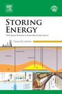
The data in Table 5.1 do not depend on the pressure of the incoming air. Although CAES invariably sucks in air from the environment at pressure p0, the overall compression might take place in multiple adiabatic stages with some cooling (called “intercooling”) between the stages. For example, a 100:1 pressure ratio, that is, r=100, can be achieved by two-stage compression with r=10 in each stage and with intercooling being introduced after the primary compression stage and again after the second stage. Temperatures would rise only to 579.2 K and the same work is done in each stage. Fig. 5.2 illustrates the trajectory of pressure and temperature in a four-stage compression process taking air from atmospheric pressure—very close to 105 Pa (1 bar)—up to 7 MPa (70 bar) with equal pressure ratios in each stage and assuming that air enters each compression stage at 280 K.
Figure 5.2Temperature–pressure plot for a four-stage compression process.
The number of stages used in a compression process is arbitrary. In general, using more compression stages reduces the total work required to compress a given quantity of air and reduces the amount (and grade) of the heat rejected from the process provided that the air is cooled again between stages. In the hypothetical extreme case where air is compressed in a very large number of stages and cooled back to its original temperature after each stage, the work required to compress some initial volume, V0 of air from its original pressure p0 up to an increased pressure p1≔rp0 is given by:
Wisoth=p0V0log(r)
(5.7)
This compression process is called “isothermal” because the air temperature remains constant throughout the process. Since the temperature remains the same between intake and exhaust, the product (p0V0) is identical to (p1V1) [see Eq. (5.1)]. The former is the work done by the atmosphere pushing ambient air into the compressor intake and the latter is the work done against air in the high-pressure reservoir pushing the pressurized air out of the compressor. For an isothermal compression process, there is no distinction between the total work done by a closed process where the same gas always remains in place (such as a piston with an airtight seal running within a cylinder) and the total work done by an open process where the gas passes through the compressor and out the other side.
The net work required to induct some initial volume V0 of air from its original pressure p0 and then compress it up to an increased pressure p1 = rp0 and discharge this air into a repository at pressure p1 with an open adiabatic compression process (an open compression process is one in which the gas passes through the compressor—for adiabatic compression, temperature rises and hence more work is done by the compressor discharging the gas into the high-pressure manifold than is recovered from the atmosphere in pushing gas into the compressor) is given by:
Wadiab=p0V0(rχ−1)χ
(5.8)
Wadiab approaches Wisoth from the previous equation, if the pressure ratio, r falls toward 1 or if χ is reduced toward 0. Eqs. (5.7) and (5.8) enable us to calculate how much air must be compressed to absorb a given amount of energy. Eqs. (5.1) and (5.2) can be used to express the quantity of this air in terms of its mass. For reasons that become clear later, it is useful to present alternative forms of Eq. (5.7) and Eq. (5.8) in terms of the mass of air compressed:
Wisoth=mRairT0log(r)
(5.9)
Wadiab=mRairT0(rχ−1)χ
(5.10)
Table 5.2 shows how much air can be compressed by 1 kW h of work (3.6 MJ) in both cases and expresses this in terms of the required intake volume—assuming that p0 is given by Eq. (5.3)—and in terms of mass of air (taking T0 = 300 K).The data in Table 5.2 show several features, of which two are very worthwhile: (a) the work per kilogram or per cubic meter of intake air initially rises linearly with the pressure ratio but rapidly becomes insensitive to the pressure ratio and (b) the distinction between isothermal and adiabatic compression is negligible at small pressure ratios but becomes very significant at larger ratios—exceeding 2:1 for pressure ratios of 100:1.
Table 5.2
Quantities of Air that can be Compressed with 1 kW h of Work
Pressure ratio, r
Isothermal compression
Adiabatic compression
Mass air/kg
Volume air/(m3)
Mass air/kg
Volume air/(m3)
2
60.31
51.26
54.53
46.35
5
25.97
22.08
20.46
17.39
10
18.51
15.43
12.83
10.91
20
13.95
11.86
8.824
7.500
50
10.69
9.082
5.804
4.933
100
9.078
7.715
4.379
3.722
Table 5.2 can be used directly in several ways. First, it facilitates assessment of the intake flow rates of a compressor for a given capacity. If a given CAES plant is required to have a 50 MW inlet capacity (= 50 000 kW) and if it used isothermal compression with pressure ratio r=100, then we can immediately realize that an air mass flow rate of at least 50 000 × 9.078 kg h–1 (= 126.1 kg s–1) would be needed. Conversely, if it used adiabatic compression the air mass flow rate would be 50 000 × 4.379 kg h–1 (= 60.8 kg s–1). Table 5.2 also enables us to quantify the size of air store required for a given stored energy. This calculation depends on the nature of the pressurized air store, so the detail of this is reserved for later.
2.2. Electrical Energy, Work, and Heat in CAES
All gas compression processes of relevance to CAES use a mechanical machine to convert mechanical work into energy within a gas of raised pressure. Similarly, all gas expansion processes relevant to CAES utilize a mechanical machine to do the reverse conversion. When a CAES system is installed as a standalone plant in an electricity grid, an electric motor is run to drive the compressor and a generator is turned by the expander. Proportionately, very small amounts of energy are lost in the motor and generator as they convert energy between the forms of electricity and mechanical work. Conversion efficiencies above 98% are quite common for large electrical machines [3] and still higher efficiencies are possible. For simplicity in this chapter, we treat electrical energy and mechanical work as being interchangeable—recognizing that in reality each time that energy is exchanged between the two forms, there will be a small fractional loss.
Despite the apparent complexity of some of the equations, there are some very simple and fundamental principles underpinning CAES. We mention three such principles here:
1. If you take some quantity of air, compress it to raise its pressure, and then cool it such that it returns to its original temperature (maintaining the pressure), then the total heat that has been drawn out of that air is identical to the net work that has been invested in the compression process. (This applies to ideal gases. For temperatures above 200 K, air can be considered to behave as an ideal gas.)
2. Any thermodynamic process is an ideal process if it is “reversible.” Any effect that causes a process to be irreversible is bad for system performance. Heat transfer across a finite temperature difference, mixing, and fluid flow across a finite pressure drop, are all instances of irreversibility occurring. Most processes used in CAES plants are intended to be as reversible as possible and any irreversibility present in a final design is either a mistake or a deliberate engineering tradeoff between system performance and increased system cost. By assuming full reversibility of all processes, we can usually reach a very quick first-order understanding of how much electrical energy we may get back out of a body of compressed air by considering how much electrical energy was required to develop that compressed air in the first instance.
3. Heat is a lower grade of energy than mechanical work (or electrical energy). In formal thermodynamics, the term “exergy” is used to indicate how much work (or electric energy) can be extracted from a system or body of material by allowing it to come back into equilibrium with its environment. Exergy is conserved except where irreversibilities destroy some of it. Exergy cannot be created. It is beyond the scope of this chapter to make a formal introduction to this most important thermodynamic quantity but we will use it nevertheless with the informal understanding given here. Note that 100 J of heat energy used to raise the temperature of some material above ambient corresponds to <100 J of exergy. Interestingly, it may sometimes require >100 J of exergy to remove 100 J of heat from some body and cause it, as a result, to become extremely cold—even with complete reversibility of all processes. However, this is no more than an interesting observation here.
With these three principles established, we can make some highly relevant calculations and reasoning. Rather than speak in generalities, we will now consider some aspects of the design of a possible CAES system that should store 1 GW h (3.6 × 10¹² J) of electrical energy, that is, 3.6 TJ of exergy. Applying Eq. (5.1), we realize that when we charge the system up completely from empty, we will have to remove exactly 3.6 TJ of heat energy from the compressed air if, as is normal, the air is to be stored at ambient temperature. Applying Eq. (5.2), we find that the nearest-to-ideal energy storage system will be one in which the expansion process should be almost an exact reverse of the compression process with heat being reinjected into the air during expansion at the same pressures and temperatures as it was removed during compression. Applying Eq. (5.3), we discover that we can make some decision about what fraction of the exergy is stored in the form of heat. If all of the heat rejected is at ambient temperature, the compression is isothermal, and the heat carries zero exergy. There is no point in storing it since there is an infinite quantity of heat at the same temperature all around. Alternatively, if the compression takes place in a single adiabatic stage, then some of that heat may emerge at very high temperatures and this heat may carry a substantial quantity of exergy. Table 5.1 showed the temperatures achieved by single-stage compression with different pressure ratios. If the pressure ratio is relatively low, the highest temperature will not be high and therefore almost no exergy can be stored as heat. If the pressure ratio is high the highest temperature will be substantial and we may store a substantial amount of exergy in the form of heat—possibly as much as one-third of total stored exergy.
This subsection brings out one of the main features of CAES—namely, that it is not simply about how to compress air and store high-pressure air. The management of heat is also important. We close by noting that if a small amount of heat, ∆Q is placed into storage at temperature, T1 the associated amount of exergy that has been stored is ∆B given by:
ΔB=ΔQ(1−T0T1)
(5.11)
The previous equation is (effectively) due to Carnot [4] and represents the maximum amount of work that a heat engine could extract from a quantity of heat ∆Q taken from upper temperature T1 and allowing that low-grade heat will be rejected into the ambient at temperature T0.
3. Air containment for CAES
Obviously, the heart of every CAES system is a store for high-pressure air. Clearly, this air store determines how much energy the system will be able to retain and it will normally comprise also the most expensive component of the system. One major attraction of CAES systems is that it may often be possible to exploit some natural phenomenon to develop stores for pressurized air that can retain very large quantities of energy at relatively low cost.
There are two profoundly different extremes of high-pressure air stores, and all practicable systems deploy stores that represent either one or the other. Fig. 5.3 illustrates the contrast. In this a vertical red line indicates that for all levels of fill, the volume occupied by the air in the store remains constant. This is termed “isochoric” (constant volume) air storage. In reality, no air store is perfectly isochoric since the volume naturally increases with rising internal pressure. However, the change in volume between minimum and maximum pressures may often be very small.
Figure 5.3The pressure–volume characteristics of high-pressure air stores.
In Fig. 5.3 the horizontal blue line indicates that for all levels of fill, the pressure of the air in the store remains constant. This is termed “isobaric” (constant pressure) air storage. Again, no real air store will ever be perfectly isobaric but some can approximate isobaric storage quite well—in that the variation of pressure may be small over the range of fill of the store.
The green curve in Fig. 5.3 indicates approximately what happens with an inflatable rubber balloon. This resembles neither isochoric nor isobaric air storage and is presented simply for illustration since most individuals are familiar with the experience of blowing up party balloons.
3.1. Isobaric Air Containment
Isobaric containments for pressurized air have the very strong engineering attraction that the compressor and expander work between (almost exactly) the same two pressures and thus they can be optimized for one single design point. Typically, all of the air present in an isobaric air store can be drawn out and we shall see that this contrasts strongly with isochoric storage. Moreover, isobaric air stores often experience lower variations in stress within the vessel since the air pressure remains essentially constant.
Isobaric air stores are the easiest ones to analyze. Consider a store with volume V1 and pressure p1=rp0. The exergy stored in this air store is equal to the work that would be done by expanding this air isothermally at ambient temperature T0, which may be slightly different from the temperature of the stored air T1:
Bisobaric_cavern=p1V1,maxT0T1log(r)
(5.12)
We shall observe in a later section that we can often recover more work from air stored in such a cavern by exploiting other exergy that is stored thermally.
There are several possible ways to achieve near-isobaric air storage. The simplest way is to employ a fixed volume containment such as an underground (or underwater) cavern of fixed shape and to allow (or force) some liquid into the cavern to displace air that has been removed (see Fig. 5.4). In this case, work is done pushing the liquid into the cavern. In some system designs, a shuttle-pond containing water or brine at the surface is connected to the bottom of a cavern and the hydrostatic head between the water surface of the shuttle-pond and the water surface within the cavern provides the pressure to drive the liquid into the cavern. Arguably, such arrangements are a combination of pumped hydro and CAES. Eq. (5.12) captures the total exergy stored, but it should be noted that some of that exergy is not actually contained within the air and lies external to the air containment. In other system designs, there may be a shuttle-pond, but the hydrostatic head may be smaller than p1. Then a pump would be needed to add additional pressure to the water/brine to drive this into the cavern, but note from Eq. (5.12) that, so long as (T0/T1)log(r) is greater than 1, the work put in by the pump is much lower than the exergy extracted from the pressurized air. Note also that (most of) this work can also be recovered as the cavern is filled with air again.
Figure 5.4Fixed volume high-pressure air store uses liquid injection for isobaric characteristic.
There are other ways to achieve near-isobaric containment. A separate chapter on underwater storage of compressed air (chapter: “Underwater Compressed Air Energy Storage”) covers both fixed shape underwater caverns, as well as deformable shapes. Both can approximate isobaric containment quite well. Another possibility [5] is to separate the volume within a fixed shape cavern into two discrete parts such that the proportion of volume occupied by either part can vary over a wide range and to fill one of those parts with a fluid such as CO2 that liquefies/evaporates at a suitable combination of temperature and pressure. As air is removed from such an arrangement, pressure tends to fall and more liquid CO2 evaporates in response to any fall in pressure—soaking in some heat from the surroundings. Then, as air is injected back into the cavern, pressure tends to rise again and CO2 gas condenses into liquid and rejects some heat into the surroundings.
3.2. Isochoric Air Containment
Isochoric containments for pressurized air are the simplest ones conceptually. They comprise one or more fixed shape volumes coupled by some arrangement of ducts, as Fig. 5.5 illustrates. An isochoric store is full when the pressure of the contained air is at its maximum allowable value p1,max, and the isobaric store is empty when the pressure has fallen to its lowest allowable value p1,min. The ratio between these two is typically less than 2—indicating immediately that when an isochoric store transitions between “full” and “empty” more than one-half of the air present in the “full” state remains present in the “empty” state.
Figure 5.5Simple isochoric containment for pressurized air.
Since the pressure within the store varies with fill level, some care is required to determine the amount of exergy stored in isochoric containment. The temperature of the stored air will remain constant if the cavern is emptied or filled slowly. We assume that this is the case:
As noted in the case of isobaric containment, the total amount of work extracted from air stored in an isochoric store may be greater than Bisochoric_cavern above if there is some storage of exergy in the form of heat.
For reasons of simplicity and minimizing capital cost of equipment, some plant designs with isochoric air stores employ a simple throttle to reduce pressure from whatever pressure is present in the cavern at one time to a constant value suitable for the expansion equipment. This measure causes some loss of exergy that could be avoided by more sophisticated (but more expensive) machinery. If all air from a cavern will be throttled down from instantaneous cavern pressure to the pressure p1,min before being passed into an expander, we obtain a lower value for the recoverable exergy:
Table 5.3 provides some insight into the contrast between quantities of exergy stored in isobaric containments, isochoric containments with variable pressure ratio machinery and isochoric containments employing throttling. In this table we assume T0=T1, p0 = 101 325 Pa and for isochoric arrangements:
p1,min=p1,max
Table 5.3
Quantities of Exergy Recoverable from Air Stores
Pressure ratio, r
Exergy (isobaric)/(MJ m–3)
Exergy (isochoric)/(MJ m–3)
Exergy (isochoric throttled)/(MJ m–3)
10
2.333
1.163
0.8248
20
6.071
3.169
2.528
35
12.61
6.737
5.615
50
19.82
10.71
9.106
70
30.13
16.42
14.18
90
41.04
22.49
19.61
115
55.29
30.45
26.77
140
70.10
38.75
34.26
170
88.47
49.06
43.09
200
107.4
59.69
53.28
3.3. Air Containment in Tanks
Of course it is possible to store compressed air in tanks above sea level or ground level, and many people have proposed tanks for this purpose. One obvious concern with the use of such tanks is that if a tank failure should occur, a large amount of energy could be released very suddenly as an explosion and the natural shielding that is provided by storing pressurized air underground or underwater largely removes that danger.
The main concern with the use of tanks either at the surface or close to it is the cost [6]. High-pressure air tanks must be built with care, and they use valuable structural material. The design of pressurized containments is a highly developed discipline, and it is beyond the scope of this chapter to explore that in depth but we can develop very good approximate insight by considering that the tanks in question will have thin walls. If the maximum pressure of interest to us is 20 MPa (200 bar) and if the material used to construct the tank has allowable stress, σmax much higher than 20 MPa, the thin-walled assumption is valid.
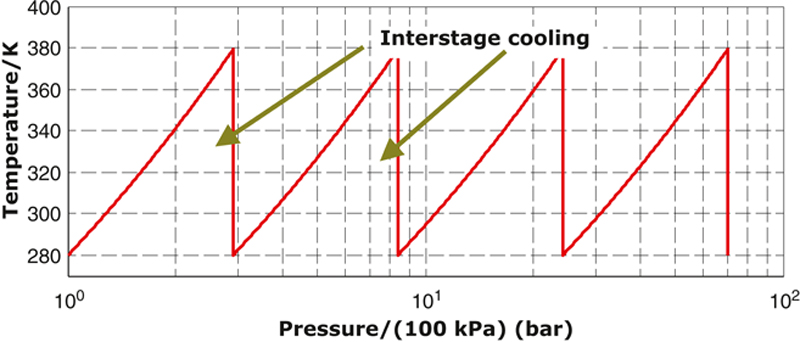
From simple mechanics (and Fig. 5.6a) a thin-walled sphere of radius R and internal pressure p1 must have wall thickness t obeying:
t>(p1−p0)σmax×R2
(5.15)
Figure 5.6Stress calculations for thin-walled tanks: (a) spherical and (b) cylindrical.
The minimum volume of material required for the sphere wall is then found to be proportional to the volume contained within the sphere by:
Vwall>V1×(p1−p0)σmax×32
(5.16)
A similar analysis can be conducted for a long cylindrical thin-walled tank radius R and internal pressure p1. From Fig. 5.6b, this must have a wall thickness t obeying:
t>(p1−p0)σmax×R
(5.17)
and substituting this thickness back to assess the volume of material required for the wall returns:
Vwall>V1×(p1−p0)σmax×2
(5.18)
Not surprisingly, comparison of Eqs. (5.16) and (5.18) reveals that the spherical tank makes best use of material. Since the two equations do not differ by much, it is conservative and reasonable to apply Eq. (5.18) as a general lower bound and to remove any constraint on the shape of the tank. It could comprise, for example, a long coil of very thin–walled tube.
Having knowledge of the volume of material required to construct a tank is a first step in estimating how much it might cost, and it also provides a very good estimation of the weight of the tank.
A brief calculation provides some interesting insight. Suppose we arrange a compressed air tank to contain 1 m3 of air at 200 bar and we allow the internal pressure to fall to 2 bar. Consider that this tank is to be constructed from steel with maximum allowable stress of 1000 MPa and density 7800 kg m–3.
From Eq. (5.13) (with T0=T1), the exergy stored in this tank is 86 MJ—about 24 kW h. For an ambient temperature of T0 = 300 K the mass of air in the full tank is 232 kg and the mass of the tank wall itself is 155 kg bringing the complete tank mass to 387 kg. A very good battery might presently achieve an energy density of 200 W h kg–1, and to store 23.9 kW h in that battery would demand a mass of around 120 kg. Evidently, compressed air stored in tanks delivers an energy density that is lower than that of present-day batteries—but not an order of magnitude lower.
Based on a present-day rough assessment of $300 (kW h)–1, this energy store might justify spending ∼$7200. This would correspond to ∼$46 kg–1 of steel. With an appropriate manufacturing route and tank design, such a value is easily achievable.
3.4. The Case for Underground or Underwater Storage
Section 3 of this chapter makes the point that the cost of storage in pressurized tanks at or near the surface is almost directly proportional to the volume of the storage and to the pressure difference between storage pressure and ambient pressure. This is not the case for stores developed either underground or underwater. In both cases there may be a relatively high fixed cost for causing any such air store to exist, but the marginal costs of increasing the capacity of that store can be very small in both cases. Fig. 5.7 illustrates this point with notional values for the case of a (fictional) cavern. A similar phenomenon happens in the context of underwater stores even though the cost per unit of energy stored tends to plateau at smaller values of stored volume.
Figure 5.7Why underground storage becomes interesting at the large scale? The y-axis is either cost/£106 or cost per unit/£ (kW h) –1.
4. System configurations and plant concepts
CAES actually represents a broad family of technologies embracing:
• numerous varieties of air compression machinery
• numerous varieties of air expansion machinery
• heat exchangers for cooling air between/within/after compression stages
• heat exchangers for heating air between/within/before expansion stages
• several options for storage of pressurized air
• several options for thermal storage to complement the stored pressurized air.
Obviously there is a broad set of possible configurations that would all fall under the aegis of CAES systems. Before highlighting some of these, it is useful to discuss one of the most commonly used classifications within CAES systems. This comprises:
• adiabatic CAES systems
• diabatic CAES systems.
The two classes are distinguished by the fact that an adiabatic CAES system does not use any external source of heat while a diabatic CAES system does make use of some external heat source to extract additional work (electricity) from the stored high-pressure air. Strictly, a diabatic CAES system is a combination of an energy storage system and a generation system since it is normal in these systems that the total amount of electricity generated from such systems exceeds the total amount of electricity consumed.
4.1. Diabatic Concepts
There are only two large-scale CAES plants in the world in operation at present: a 321 MW plant belonging to E.ON Kraftwerke, Huntorf (Germany) and the 110 MW plant of PowerSouth Energy Cooperative in Alabama (United States). Both plants use underground salt caverns for storing the air. Both are diabatic insofar as they do not store heat [7] but burn a fuel to heat the air before expansion. Fig. 5.8 presents the simplest format of a diabatic CAES plant.
Figure 5.8A simple diabatic CAES system.
Here the same electrical machine (labeled M/Gen to indicate that it can act as either motor or generator) can be coupled either to the set of compressor stages or to the expander via the clutches shown in Fig. 5.8. An alternative to having these two clutches is to duplicate the electrical machine so that one machine always acts as a motor when it is in operation and the other always acts as a generator.
The exhaust gas in Fig. 5.8 may exit at a temperature substantially above ambient, and in this case it is clear that exergy is being wasted. An alternative system that does not waste any exergy is shown in Fig. 5.9. Here, a recuperator absorbs heat that is left in the exhaust gas leaving the (final stage of the) expander and transfers this heat to air coming from the high-pressure air store before it reaches the (first stage of) expansion.
Figure 5.9A simple diabatic CAES system with recuperator.
It is not essential that the expansion process should comprise only a single stage of expansion. By having more than one stage (together with a recuperator), it is possible to extract substantially more work from the stored air. Fig. 5.10 shows a schematic for such an arrangement.
Figure 5.10A diabatic CAES system with recuperator and two-stage expansion.
Fig. 5.11 shows the temperature–pressure profile for the air in the case of Fig. 5.10. In this the recuperator raises the temperature of the air leaving the tank to 800 K by cooling the air exhausted from the second expansion stage back down to ambient temperature. A combustor then adds further heat to the air entering the first stage of expansion to raise its temperature to 1585 K. After the first expansion stage, a second combustor raises the temperature again to 1585 K before the second expansion stage, which again reduces the temperature to 800 K.
Figure 5.11Temperature–pressure plot for a diabatic CAES system with recuperator and two-stage expansion.
4.2. Adiabatic Concepts
The term “adiabatic” suggests that no heat is drawn into a process or expelled from that process. Strictly, the term is misused in the context of adiabatic CAES systems. The real meaning is that no net external heat source is used. However, heat may be exchanged with the environment.
Fig. 5.12 shows one of the simplest possible adiabatic CAES system structures. In this, multiple stages of compression with interstage cooling approximate an isothermal compression process. Similarly, multiple stages of expansion with interstage reheating from the environment approximate isothermal expansion.
Fig. 5.13 depicts another possible adiabatic CAES system structure. In this, one single compression stage raises the temperature and pressure of air. Heat is drawn from the air and stored in a thermal store before the air is fed into storage. The same heat is injected back into the air when the air is withdrawn from storage prior to expansion.
Figure 5.13An adiabatic CAES plant with thermal storage.
If the same size and type of air store is used for the systems of Figs. 5.12 and 5.13, the total storage capacity of the latter system will be much larger since exergy is stored in the thermal store as well as in the compressed air store. It is commonly stated that the purpose of introducing thermal storage into CAES is to improve efficiency. This is quite incorrect. Systems such as that depicted in Fig. 5.12 can be made arbitrarily efficient by using a sufficient number of high-efficiency compression and expansion stages and by demanding high effectiveness of the heat exchanger units—though they would become very expensive. The main motivation for introducing thermal storage to a CAES plant is to increase the total quantity of exergy that can be stored for a given size of pressurized air store.
We have seen in the previous section that CAES installations may be either diabatic or adiabatic. In both cases, air is preheated prior to the expansion process—largely for the purposes of extracting more work from the same quantity of compressed air, but partly motivated by avoiding very low temperatures that could cause problems of water or lubricant freezing. In the case of adiabatic CAES plants the heat is stored from the air compression and used again to support expansion.
Thermal energy storage is itself a very large discipline, but its importance is so great in the context of CAES systems that it demands at least some discussion here. The requirement is to be able to transfer heat in and out of a pressurized air stream. If compression and expansion are both single-stage processes, then there is only one pressure to consider for thermal storage. If they both take place in, say, three stages, then there are three separate pressures to be handled by the thermal storage. For reasons connected with minimizing the destruction of exergy by forcing heat transfer to take place across large temperature differences, a well-designed adiabatic CAES plant will always use the same number of stages for compression and expansion.
It takes only a little consideration to realize that there are two major options for thermal storage in conjunction with CAES [6]:
1. Heat is stored within the pressurized system and the high-pressure air circulates around it.
2. Heat is stored outside the pressurized system and transferred across the walls of that system.
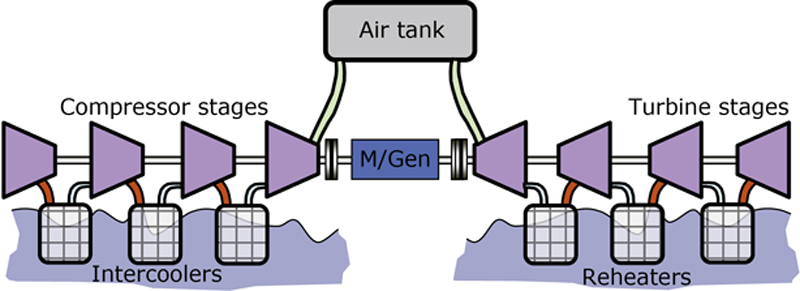
Fig. 5.14 makes the contrast clear. In Fig. 5.14a, a pressurized containment contains the thermal storage medium—shown as bricks. In such cases, heat transfer between the pressurized air and the thermal storage medium may be extremely good and one may achieve very good thermocline behavior (as shown in Fig. 5.15) where a sharp thermal gradient exists between a portion of the thermal store that is hot and another part that remains cool. In Fig. 5.14b, by contrast, a pipe containing pressurized air is shown running through a thermal storage medium that is not pressurized.
Figure 5.15A thermocline-type packed bed heat store.
The main disadvantage of the first option (Fig. 5.14a) is that one requires a large pressure vessel that may not be able to exploit any geological/geographical features for strength. One rather elegant solution is noted in [8] where thermal energy is stored within the same cavern used for the pressurized air, but this is not applicable in most situations.
If the material within was some rock with specific heat 850 J (kg K)–1 (typical of a wide variety of rocks) and if the temperature swing in that rock was, say 500 K, then each 1 m3 volume of space within the containment would account for ∼640 MJ of heat (assuming that the mass of rock in each 1 m3 volume is 1500 kg). Note that this value is independent of pressure. Comparing this quantity of energy with the values in Table 5.3 shows that energy density is quite good relative to the energy stored in the compressed air itself for all realistic storage pressures. However, pressure containment is still expensive and is made more complex by the fact that this containment may have to operate at quite high temperatures (further weakening the containment material).
The main shortcoming of the nonpressurized thermal storage of Fig. 5.14b is that heat transfer is much more indirect between the pressurized air and the thermal storage medium. Numerous creative solutions are being considered for how best to achieve reasonable heat transfer in such contexts.
5. Performance metrics
It is commonly asserted that CAES does not deliver a high-performance energy storage solution. In fact, this position is mainly derived from an erroneous assessment of the performance of the two large-scale diabatic CAES plants—at Huntorf (Germany) and McIntosh, Alabama (United States). Published data, for example reference [7], reveal that to achieve 1 kW h of electrical energy output, 0.8 kW h of electricity is drawn into the plant at Huntorf together with 1.6 kW h of gas. Similarly, to achieve 1 kW h of electrical energy output from the CAES plant at McIntosh, 0.69 kW h of electricity is drawn in together with 1.17 kW h of gas. Performing a straight “output-divided-by-input” calculation suggests that:
ηHuntorf=10.8+1.6=41.7% ✗ and ηMcIntosh=10.69+1.17=53.8% ✗
These values are unrepresentative because they fail to recognize that every diabatic CAES plant is really a combination of a pure energy storage plant and a generation plant. The aforementioned calculations add electrical energy to thermal energy as though 1 kW h of heat was equivalent to 1 kW h of electricity. This is wrong. In fact, the best performing combined cycle generation plants return 60% of the calorific value of the fuel consumed. On this basis, we can obtain much more representative values for the performance of the two long-extant CAES plants:
ηHuntorf=10.8+0.6×1.6=56.8% ✓ and ηMcIntosh=10.69+0.6×1.17=71.8% ✓
The reason that McIntosh performs rather better than Huntorf is connected mainly with the recuperator. Note also that both Huntorf and McIntosh presently use throttles to deliver constant pressure air to the expanders. The alternative would be to use a small high-pressure reciprocating machine or a number of dynamic machines in series to extract exergy as the air pressure is reduced.
Employing Eqs. (5.13) and (5.14) and the knowledge obtained from reference [7], shows that Huntorf caverns operate between 5 MPa (50 bar) and 7 MPa (70 bar). this indicates Huntorf loses 4.4% of the exergy available from the cavern in each cycle. Since that exergy comprises around 43% of total exergy including that from fuel, the improvement that could be achieved by replacing the throttle at Huntorf is around 1.9%, that is, raising its effective turnaround efficiency to 58.7%.
The plant at McIntosh runs from 4.5 MPa (45 bar) to 7.6 MPa (76 bar) and thus loses 6.6% of the available cavern exergy in the nozzle. Moreover, the cavern exergy there comprises around 47% of total exergy, and hence 3.1% improvement in effective turnaround efficiency is possible—raising this to 74.9%.
Other measures can be taken to achieve still higher performance, but, of course, all have associated costs.
6. Integrating CAES with generation or consumption
Since CAES intrinsically involves both heat and mechanical work, there are strong opportunities for integrating this with either electricity generation or consumption. The basic arguments for doing this are straightforward. Standalone energy storage for supporting the electricity system requires that energy is converted from one form of electricity to another form compatible with storage and back again, causing two additional sets of energy losses in transformation and requiring additional machinery to effect the transformations. By integrating energy storage with generation, these additional losses and costs may be reduced or avoided [9]. Various proposals have come forward for integrating compression with wind turbines [10,11] and for integrating compression with wave energy [12] and tidal energy [13,14]. For generation from wind, wave, and tides, the conversion efficiency from input energy to electricity is virtually irrelevant and what matters is the combined capital and operational costs of the energy harvester devices per kilowatt-hour of electricity produced. For sound engineering reasons, outlined in [11], exploiting air compression as the primary means of carrying away power from the device can account for significant cost reduction compared with direct generation of electricity. It is to be expected that as more CAES plant will emerge in the near future, there will be an increase in interest in capturing compressed air directly from renewables.
CAES also provides for integration on the consumption side. We noted at the outset that substantial fractions of the electricity supply are presently used to compress air [1], and it follows that if suitable receivers are in place at those locations that use compressed air, these may act as excellent energy stores—obviating the requirement for any new power conversion machinery and avoiding virtually all losses normally associated with storage. One other possibility deserves particular mention: data centers are progressively consuming more and more of all electricity generated and these have very particular requirements for both cooling and power that are especially well suited to CAES. If high-pressure air is stored at near-ambient temperature and then expanded in several stages, it can deliver both cooling and electrical power in equal measure—fitting exactly the requirements of a data center.
7. Concluding remarks
The application of air compression to decouple energy absorption from the grid and energy consumption is known and has been practiced for decades. Two large-scale CAES power plants are in operation today, using salt caverns as storage, and both of these burn a fuel to maximize the energy recovered from the stored air. There are many different possible configurations of the CAES system and most of those presently proposed do not combust a fuel. CAES plants can be highly cost-effective and they can deliver very respectable turnaround efficiencies. The containment for high-pressure air is at the heart of every CAES system. Storage of air in man-made tanks has been discussed in this chapter, but this comes at a cost per unit of energy stored that may be two orders of magnitude higher than what may be achieved with underground or underwater storage of the air. For this reason, separate chapters are devoted to these two possibilities.

 (5.4)
(5.4) (5.5)
(5.5) (5.6)
(5.6)
 (5.8)
(5.8) (5.10)
 (5.11)
 (5.12)

 (5.13)
 (5.14)
 (5.15)
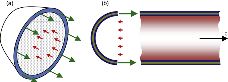
 (5.16)
 (5.17)
 (5.18)


 ✗ and
✗ and  ✗
✗ ✓ and
✓ and  ✓
✓