Traditional Bulk Energy Storage—Coal and Underground Natural Gas and Oil Storage
Fritz Crotogino R&D Department, KBB Underground Technologies GmbH, Hannover, Germany
Abstract
Just like renewables, conventional fossil fuels such as coal, natural gas, and oil also have to be stored with capacities of up to grid scales. In some cases, reserves can satisfy demand for several weeks. The main motive for operating bulk storages is minimizing the amount of investment required in the transport chain by maintaining steady transport flows, as well as the creation of strategic stockpiles and safeguarding supplies against technical and climatic risks. In recent years energy trade has become another motive for bulk storage. Natural gas, in particular, is stored in very large quantities in deep underground geological formations because this is a very safe and low-cost option. The storage facilities are mainly constructed in natural porous reservoirs such as depleted gas fields or in man-made salt caverns. The engineering methods and the application of future grid-scale storage facilities for electricity generated by fluctuating wind and solar power are primarily based on the many decades of experience gained in the storage of natural gas. This applies to the storage of electricity via compressed air (physical storage), hydrogen generated by electrolysis, and synthetic methane formed by combining such hydrogen with carbon dioxide (chemical storage)—all mainly stored in salt caverns
Keywords
bulk storage
grid-scale storage
strategic reserve
oil
coal
natural gas
depleted reservoir
aquifer
salt cavern
1. Introduction
The purpose of the chapter is to dispel the widely held belief that the need to store large volumes of energy to balance out production and demand is a special aspect which primarily only affects an energy system based on fluctuating wind and solar power. This opinion has been frequently used as an argument against the establishment of renewables as part of energy transition. According to the same lobbyists, there are hardly any suitable storage technologies available to hold large volumes of electrical energy.
This argument overlooks the fact that as the demand for energy rose exponentially as a result of industrialization in Europe and the United States, in particular, instead of being extracted in the vicinity of areas with the highest demand, fossil fuels in the form of coal, oil, and natural gas increasingly had to be transported long distances by rail, ship, or pipeline—leading to the knock-on effect of having to construct storage facilities close to the main centers of demand. The specific reasons for this included:
• The fact that coal, oil, and natural gas tend to be produced at a more or less steady rate, which is frequently out of step with varying demand at a range of timescales (such as seasonally dependent gas consumption for heating purposes).
• The transport chain is designed for continuous transport rates with as little fluctuation as possible to keep the enormous investment costs as low as possible, and so as not to have to design them to cope with demand peaks (e.g., oil pipelines several thousands of kilometres long from Siberia to Central Europe).
• The discontinuous demand from, for example, a power plant, which is dependent on time of day, week, day, and season.
• Reserves to compensate for stoppages along the transport chain.
• Reserves for periods of unusually high demand, for example, during longer intense periods of frost.
If one then casts an eye on a future energy system relying on renewables, one sees many parallels with respect to the demand for storage space, including aspects such as the transport of wind power from coastal areas to inland regions, the general balancing out of production and demand, as well as the need for reserves to compensate for unforeseen technical or political events.
Another, and actually more important, purpose for the chapter is the fact that the crucial technologies to be used in future for grid-scale storage of electrical energy from renewables are largely based on technologies which have been tried and tested for several decades for the storage of liquid and gaseous fossil fuels in underground geological formations.
The timing of the production of primary energy sources and the actual demand for electricity rarely coincide perfectly for energy systems based on either conventional fossil fuels or tomorrow’s renewable energy sources. Both require large storage capacities to balance out production and demand at the grid scale.
The major advantage of supplying power in an energy system based on fossil fuels is, however, that the primary energy sources are chemically bound up in coal, oil, and gas before being converted into electricity in a power plant. First, this means very high volumetric energy storage densities—a medium-sized car can drive up to 1000 km on one tank of petrol. Second, fossil fuels can easily be stored on the surface or below ground. This makes it possible to generate electrical energy in tune with demand, which reduces the need for power storage capacities. Actual storage is primarily provided here by the primary fossil fuels themselves. This is highlighted by the fact that Germany, for example, has stockpiles of natural gas which could satisfy demand for approximately 4 weeks, but only has storage capacities for less than one hour of electrical energy: a ratio of around 5000/1!
Therefore, while the previous energy system primarily depended on primary fossil fuels or energy sources, a future energy system largely based on wind and solar power1 produces electrical power as the primary energy source. Outsourcing the storage function to fossil fuels is therefore ruled out in this case. This means that power first has to be converted into a storable medium to be able to store the large volumes of energy necessary (in the gigawatt hour to terawatt hour range)—if one excludes batteries which are primarily suitable for smaller capacities.
The following sections look at the surface storage of large volumes of coal, the storage of oil underground in artificially constructed salt caverns, and the storage of natural gas in various geological formations.
2. Coal
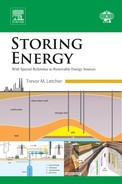
Today, coal forms the basis for one-quarter of global energy consumption and forms over one-third of power production. The most important coal-exporting countries are Indonesia, Australia, Russia, the United States, Colombia, South Africa, and Canada, while the most important importing countries are China, Japan, India, South Korea, Taiwan, Germany, and the United Kingdom (Fig. 19.1) [1]. This makes it clear that considerable effort is usually required to transport coal to far-flung centers of consumption, such as Europe, and that this must be maintained at the most continuous level possible to optimize the investment costs for rail and ship transport. Various storage facilities therefore have to be integrated along the transport chain from the mine producing the coal to the consumer—primarily power plants and the steel industry. The tasks typically undertaken by storage facilities include:
• Balancing out continuous coal production and discontinuous rail and long-distance ship transport to import terminals in distant sales markets.
• Balancing out discontinuous rail and inland ship transport from import terminals to power plants and other major consumers.
• Stockpiling at the sites of major consumers to bridge temporary stoppages along the transport chain to end–consumers, for example, complete stoppage of inland waterway transportation in extreme winters.
• Stockpiling at power plants to satisfy long-term above-average demand for coal-generated power during long periods of calm in countries with a high proportion of wind or solar power.
• Stockpiling at power plants, in general, to generate so-called residual load—the difference between the capacity of priority power generated by fluctuating wind turbines and photovoltaic plants and grid load.
• Stockpiling different qualities of coal held by large consumers to create optimal coal mixtures.
Large stockpiles of coal are complemented by the enormous total capacity of transport ships themselves. European import seaports, for example, Rotterdam, have coal stockpiles with a capacity of up to several million tonnes—energy content2 of c. 8000 GW h for every 106 t)—which are needed for rapid handling and therefore are not used as reserve storages.
The capacity of stockpiles held at power plants typically range from a few tens of thousands of tonnes to up to a few hundreds of thousands of tonnes corresponding to (80–800) GW h. One of the largest power plants in Germany has coal stockpiles with a theoretical capacity of over 350 000 t (2 800 GW h): this amount would be adequate for a period of approximately 4 weeks during an emergency.
However, these figures are not very suitable for estimating the capacity of reserve stockpiles because differentiation is required between active and passive stockpiles. Active stockpiles are used for coal deliveries and supplying the power plant. Passive stockpiles alone can be used as long-term storage. Most locations do not have any passive stockpiles, and many types of coal are unsuitable for long-term storage because they have a tendency to self-ignite. Therefore, they represent a high level of risk to the environment, operations, and invested capital!
Different types of coal storage are used in practice:
• A heap stockpile is an open stockpile of solid fuel which is therefore exposed to the weather. This type of storage is very simple and easy to implement for large volumes
• Bunker and shed stockpile
The reason for using closed storage areas is usually to avoid polluting the environment with emissions of dust, and to prevent water contamination. Fire protection expenditure is much higher than in the case of open heaps. Potential capacities are of up to 10 000 t—in other words, much lower than open storage areas.
3. Oil
Oil is still the paramount energy source worldwide, ahead of coal and natural gas. In a similar way to the situation affecting coal, oil must in most cases be transported long distances, in this case by pipeline and/or ship from major oil fields to the main centers of consumption.
Storage is therefore a very important element in the oil transport chain. Large storage systems are required for maritime transport at export terminals, import terminals (in particular), and where international pipelines interface with transport and distribution networks. However, the largest demand for storage is the holding of strategic reserves to guarantee supplies of oil during periods of crisis.
The most well-known features of oil storage facilities are the surface oil tanks shown in Fig. 19.2 (an aerial photograph of a tanker unloading) together with the terminal and tank farm at NWO, Wilhelmshaven (Germany) [2], which forms the interface between incoming tanker loads and long-distance pipelines. Twenty six tanks are available for interim storage, each holding around 30 000 m3 (324 GW h3), as well as nine tanks with capacities of around 100 000 m3 (1 080 GW h). The total capacity of the tank farm is 1.6 × 10⁶ m3 (17 300 GW h). The main purpose of this tank farm is to act as a buffer so that oil tankers can be unloaded within a few hours, before the oil is transported onward in long-distance pipelines or held for long-term storage in caverns, see later discussion.
Today’s standard tank farms place high priority on protecting the environment and, in particular, the hydrosphere, for example, a containment wall around each tank which can hold back the oil in the unlikely event of a leak. However, the tanks can only be protected to a certain extent against external influences.
An alternative to surface tank farms are man-made cavities constructed in underground geological formations below the groundwater horizon. The surface facilities of these underground storage caverns consist largely of a pump station and the connecting pipelines. As a result of the storage being deep underground, there is far less risk to soil, drinking water, or groundwater contamination. Furthermore, underground storage has the advantage that in the event of technical malfunctions or terrorist attacks there is no surface storage plant or structure that can be damaged, destroyed, or result in dangerous leaks. Other advantages include much lower costs and a much smaller footprint.
The main underground storage options are artificially constructed salt caverns, followed to a lesser extent by rock caverns constructed by conventional mining, and in a very few individual cases old abandoned mines.
3.1. Salt Caverns
A special characteristic of salt caverns is the possibility of constructing the caverns from the surface by drilling a well down into the salt formation. Water is pumped down this well after installing cemented casing strings and temporary pipes. The water dissolves the rock salt to create the cavity with the required shape. The brine produced as a result of dissolution of the salt is displaced to the surface where it is disposed of in an environmentally friendly way, or used as a raw material. Fig. 19.3 is a schematic diagram of a completed oil cavern in operation. For a more detailed description of salt storage caverns see Section 4 on natural gas and salt caverns.
Two methods are available for the operation of caverns storing liquids:
• Using pumps in a similar way to a tank: a submersible pump is installed in a withdrawal pipe (string) above the cavern sump to remove the storage product. The cavity above the top of the product is filled with air. This method is rarely used in the case of salt caverns because having atmospheric pressure in an air-filled space is only possible at low depths because of the need to maintain the stability of the caverns.
• Using brine displacement (Fig. 19.3): the oil is stored in equilibrium with the brine from the former solution-mining process. Because brine is heavier than crude oil the oil sits above the brine and no mixing occurs. When brine is pumped into the cavern via the brine string, it displaces the crude oil through the annulus to the surface and then into the delivery pipelines. During filling the cavern oil is pumped through the annulus into the cavern, where it displaces brine via the brine string, which is sent to a surface brine storage reservoir and eventually reused in the storage and distribution process.
The disadvantage of this method is that if it is to be used regularly, a brine pond is required on the surface with the same volume as the cavern. In practice, brine buffer ponds are largely only used for liquid gas storage caverns because of the more frequent cycling of the operation.
In the case of strategic crude oil storage for emergency use, it is possible to use water instead of brine to displace the oil. However, the use of water increases the volume of a cavern by c. 15% every time the oil is removed. This is due to the solubility of the salt and is the reason the caverns in the German strategic reserve are only designed for a maximum of five cycles (Table 19.1).
Table 19.1
Typical Data for an Oil Storage Cavern in a North German Salt Dome
Average depth/m
1 400
Volume/m3
400 000
Max. diameter/m
50
Height/m
600
Max. rate (in/out)/(m3 h–1)
400
Energy content, calorific value/GW h
4 320
Max. capacity (in/out)/GW
4.3
3.1.2. Important Oil Storage Facilities Realized in Salt Caverns
In practice, commercial operating storage facilities for crude oil are generally built on the surface primarily because the construction of tank farms is not dependent on the availability of suitable salt formations and because the expense involved in planning, authorizing, and operating surface brine ponds is fairly considerable. One of the exceptions is the Louisiana Offshore Oil Project (LOOP) in the vicinity of New Orleans, Louisiana (United States), which serves as the largest import terminal on the Gulf of Mexico. There are also two very large strategic oil reserves worldwide—in Germany and in the United States—using salt caverns and scheduled for use during periods of crisis. The main reasons for using the salt cavern option in these cases are the much lower investment costs and much higher security and safety.
In Germany the Crude Oil Storage Association (EBV) operates 4 coastal sites with a total of 58 caverns and a total volume of 12.5 × 10⁶ m3, corresponding to around 135 000 GW h or 135 TW h. This is around 60% of the reserves. The oil stored in these reserves is exclusively intended for maintaining supplies during a crisis and can therefore not be used for government price regulation purposes, for instance. The Netherlands and Portugal lease storage capacity for strategic reserves from other cavern operators [3,4].
The Strategic Petroleum Reserve (SPR) of the US government comprises a complex of four sites with deep underground storage caverns created in salt domes along the Texas and Louisiana Gulf coasts. The caverns have a capacity of 116 × 106 m3 corresponding to around 1.3 × 10⁶ GW h or 1,300 TW h and store emergency supplies of crude oil [5]. Unlike the conditions existing in Germany the US government can also use storage facilities for price regulation.
3.2. Rock Caverns
Conventionally mined rock caverns are underground cavities constructed by using conventional mining techniques (shaft sinking, excavation of cavities by blasting or cutting). Mined rock caverns can be constructed in a certain range of geological formations which need to allow for the construction and operation of large, long-term stable caverns. These formations were initially considered intrinsically impervious to water and hydrocarbons. Later designs in fractured rock used the head of water as a water curtain (hydrodynamic containment) to contain the hydrocarbons (see later).
Rock caverns have been developed primarily for the storage of liquid hydrocarbons like oil, gasoline, and liquid petroleum gases (Fig. 19.4). Most of these developments were started in the United States after World War II. Other countries such as the Scandinavian countries, France, and South Korea followed in the time between 1960 and the 1980s, and in the 1990s East Asian countries such as China, Japan, and India followed suit. All these countries have abundant suitable sound rock available. A recent example is Singapore’s Jurong rock cavern project launched in 2014. The caverns are located at a depth of 130 m and are designed for liquid hydrocarbons such as crude oil, condensate, naphtha, and gas oil. The first phase comprised five 340 m long caverns with nine storage galleries providing 1.470 × 10⁶ m3 of storage, and 8 km of tunnels costing some US$1.3 × 10⁹ (US$1.3 billion). The second phase is planned to double this capacity [6].
Caverns using hydrodynamic containment are based on the principle that the requisite strong and competent rocks typically have fractures and fissures and are therefore not impervious to liquids (and gases). The fractures and fissures, on the other hand, lead to an inflow of water if groundwater is present, or if water is artificially provided and if the storage pressure is kept below the water column pressure. The pressurized water flow then prevents the escape of the storage product to the hydrosphere. The small amount of inflowing water is collected in the cavern sump, pumped to the surface, and disposed of after eliminating traces of the hydrocarbon product.
As expected the investment costs of conventionally mined caverns are much higher than those of salt caverns which are developed from the surface.
4. Natural gas storage
With a share of 24% (as of 2013), gas is the third most important primary energy source after oil and coal. Burning natural gas is considered by many as a “bridging technology” along the long journey to creating an energy system based largely on renewables—which is why gas is still considered to have major growth potential in the foreseeable future.
The world’s largest natural gas producer by far is Russia, followed by Qatar, Iran, China, Saudi Arabia, and Algeria. In a similar way to coal and oil in many aspects, natural gas also has to be transported very long distances from the gas fields to the major centers of consumption—via pipelines on land or as liquefied natural gas in LNG carriers crossing the major oceans.
The development of gas infrastructures began as early as the middle of the 19th century in industrially developed countries such as the United Kingdom and Germany—initially involving town gas generated from coal. Low-pressure surface tanks were initially developed to store the town gas, followed by pressurized tanks whose capacities, however, were still very restricted because of the low operating pressures and their relatively small volumes.
Town gas was replaced by natural gas in the middle of the 20th century after the discovery of major fields in the Netherlands, Russia, and in the North Sea—particularly in the British and Norwegian sections. This transition changed the previously locally structured gas industry into a regional, national, and increasingly international industry based on an international network of interconnected pipelines with major integrated storage facilities.
The first experience with storing gas underground in depleted oil fields and, particularly, depleted gas fields as well as in water-bearing reservoirs (so-called aquifer formations) and in artificially constructed salt caverns had already been acquired during the town gas era. Deep underground geological formations are particularly attractive for the storage of gas because it can be stored at high pressures, unlike the large tanks on the surface which are limited to relatively low pressures. Another advantage of underground gas storage is that very large geometrical storage volumes can be created. The combination of high pressures and large volumes are the factors which enable gas storage facilities to achieve extremely high energy storage capacities, even though the density of the gases, even after compression, is relatively low compared with liquid or even solid fuels.
The operation of underground gas storage facilities usually involves injecting the gas into the storage cavern under pressure, and withdrawing it at a later date by releasing the pressure. This means that underground storage is not only possible in open cavities—such as artificially constructed caverns (see sec. 3.1)—but also in natural reservoirs consisting of a matrix of countless interconnected microscopic pores. A special feature of storage operations involving compression and pressure release is that operational injection and production pressures must stay within a range between a minimum and a maximum operating pressure. The storage capacity achievable within this range is called the working gas. Residual gas which remains in the storage below the minimum pressure is called the cushion gas. Depending on the storage technology the ratio of working gas to cushion gas ranges approximately from 2:1 in gas caverns to around 1:1 in pore storage sites. Expenditure for the cushion gas needs to be considered as part of the investment costs.
The following describes the most important storage options for natural gas in detail. Large-scale storage discussed in chapter: Larger Scale Hydrogen Storage describes the storage options available for hydrogen largely based on options developed over many decades for the storage of natural gas.
4.1. Depleted Oil and Gas Fields
Oil and gas fields are the product of long-dead residues of plants and small animals locked into rocks many millions of years ago and buried for long periods of time at great depths under high pressures and high temperatures. Because of the low permeability of earlier laid-down rocks compared with the overlying more permeable rocks, the hydrocarbon fluids generated later migrated upward. In some cases the hydrocarbons were prevented from rising up further by the presence of overlying impermeable rock layers (cap rock) which then contained the hydrocarbons in so-called traps. This gave rise to the existence of today’s oil and gas fields (reservoirs) in the porous horizons beneath cap rocks (Fig. 19.5).
Figure 19.5Natural gas storage in depleted gas reservoir.
Oil and gas does not naturally collect in large open cavities, but in a matrix of countless tiny interconnected pores within a “reservoir”. Numerous wells normally have to be drilled to release the oil and gas in the reservoir discovered by exploration because flow resistance in the matrix of pores over excessively long distances in the field would overly restrict the production rates that could otherwise be achieved.
Oil and gas fields, which have been largely depleted, can be converted into natural gas storage spaces if certain conditions required for subsequent storage operations are satisfied. In some cases, existing wells can be utilized further for the injection of gas. The major benefit of depleted oil and gas fields is that the tightness of the reservoir has already been proven by its existence over geological time periods. Because of flow resistance in the pore matrix associated with the system, depleted oil and gas fields are primarily suitable for seasonal storage operations, that is, injection in the summer half of the year and withdrawal in the winter half of the year—and are therefore less suitable for flexible operations with frequent cycles and high production and injection rates. In some cases these disadvantages can be compensated for to a certain degree by using increasingly utilized horizontal drilling technology.
Although oil fields are in principle just as suitable for conversion to gas storages as a depleted gas field, gas fields tend to be used much more frequently in practice because the higher hydrocarbon fractions from the oil in a depleted oil field have negative effects on natural gas storage operations. Moreover, not every depleted oil and gas field can be converted into a gas storage facility. Crucial prerequisites are adequate permeability and porosity of the reservoir rock to facilitate the production and injection rates necessary for storage operations and suitable depths because excessive depths are associated with uneconomically high storage pressures (Table 19.2).
Table 19.2
Advantages and Disadvantages of Gas Storage in Depleted Oil and Gas Fields
Advantages
Disadvantages
Use of existing reservoir
Low deliverability per well
Excellent knowledge of reservoir (geology, performance)
Maximum (0.5–1)% daily withdrawal of total capacity
Low investment costs for conversion
Maximum 1–2 turnovers per annum low deliverability and injectivity
Possibility of reusing existing wells
High percentage of cushion gas
4.2. Aquifer Storage
The geological sequence of rocks in the Earth’s crust consists of impermeable as well as porous, permeable formations. The porous, permeable formations are known as reservoirs, or when they are filled with groundwater (which is generally the case), as aquifer formations or simply aquifers.
In certain cases, such mostly saline groundwater-filled nondrinking water aquifers lying at great depths can also be used for the construction of gas storage facilities, by injecting gas into the formation via wells to displace the water laterally and downward. The starting position is more challenging than in the case of an oil or gas field because the tightness of the top of the reservoir has not been confirmed over long periods of time by the trapping of light hydrocarbons. The first condition that has to be met to verify the suitability of an aquifer for the construction of a gas storage facility is therefore confirmation that the overlying rock layer is impermeable to gas. Another requirement is the presence of a dome-shaped structure below the cap rock to enable subsequently injected gas to remain trapped within a large but controllable volume—in other words, the gas does not simply flow away through the sides in an uncontrolled manner. If these conditions are satisfied the reservoir still has to have adequate porosity and permeability to enable subsequent storage operations to be realized at the necessary injection and production rates.
Unlike the situation encountered in a depleted oil and gas field, which has already benefited from extensive exploration in the runup to the start of production operations, the geology of an aquifer, its structure and lithology, and its reservoir-engineering properties, are generally largely unknown. This means that a very extensive step-by-step exploration campaign is necessary to verify the suitability of the aquifer for the installation of a gas storage facility.
Exploration involves seismic methods to explore the structure of formations; several exploration wells to extract rock samples to determine the material parameters and to carry out pump tests to evaluate intrinsic reservoir properties; and then simulation of the storage operations based on these data. The exploration phase can take several years and is associated with the risk of ultimately not being able to confirm suitability.
If the exploration phase is completed successfully the next step is the drilling and completion of numerous wells because flow resistance in the pore matrix has to be overcome in just the same way as in an oil and gas field. If the distances between individual wells in the reservoir are too great, this would severely restrict achievable production and injection rates (Table 19.3).
Table 19.3
Advantages and Disadvantages of Gas Storage in Aquifer Formations
Advantages
Disadvantages
Use of existing reservoirs
Need for extensive, costly, and time-consuming exploration phase
No hydrocarbon residues in reservoir, which might contaminate storage product
Low deliverability per well
Maximum (0.5–1)% daily withdrawal of total capacity
Maximum 1–2 turnovers per annum
Low deliverability and injectivity
High percentage of cushion gas
We conclude this section by pointing out that a large number of aquifer storage facilities have in the past, been set up worldwide despite the aforementioned disadvantages. However, in certain areas, such as in central France, no suitable depleted reservoirs or salt formations are available. Finally, because of the costly exploration phase, as well as technical problems, only a few additional aquifer storage facilities have been set up in Europe over the past few years.
We conclude this section by pointing out that a large number of aquifer storage facilities have been set up worldwide despite the aforementioned disadvantages. This is due to the depleted oil and gas fields that are available and the fact that there are large regions with storage needs, such as in France, where there are no suitable salt formations, oil fields, or gas fields in most industrial regions. Because of the costly exploration phase, as well as technical problems, only a few additional aquifer storage facilities have been set up in Europe over the past few years.
4.3. Salt Caverns
Salt caverns are artificially constructed cavities in salt formations. The special properties of rock salt allow:
• cost-efficient construction of cavities with very large volumes by solution mining through a well drilled from the surface
• stable operations over long periods of time without any internal structural installations
• safe containment of liquids and gases under high pressure
• storage of very large volumes of liquids and gases at high pressures and, therefore, large amounts of energy.
Construction involves drilling a well deep into the rock salt with a diameter of d < 1 m (Fig. 19.6). Several pipes—so-called casings—are installed in this well in a telescope-like arrangement and bonded with cement to the surrounding rock to make the casings gas tight. Two additional casings are suspended in the well to construct the cavern during the solution-mining process. Water is injected into the inner pipe string to dissolve the salt. The brine which this produces is displaced to the surface through the inner annulus or reverse. A protective fluid (blanket) is injected into the outer annulus to prevent uncontrolled upward solution of the salt formation. The brine produced by solution mining must be disposed of in an environmentally compatible way, for example, by pumping it into the sea. Alternatively, it can be used as a raw material for salt production or by the chemical industry.
Once the cavern has reached its final volume a test is carried out to confirm the tightness of the cemented casings. After a successful test the gas production string is then installed by sealing off the annulus from the inner cemented casing and filling it with a protective liquid (Fig. 19.7). In the unlikely event of a leak into this casing, this leaking gas would be immediately detected because this would cause the gas in the fluid to immediately rise upward. This crucial safety feature is supplemented by a subsurface safety valve which closes automatically if the cavern head at the surface becomes damaged. However, before this valve can be installed, the remaining brine in the cavern has to be displaced to the surface via a “brine displacement string” by the storage gas injected.
Salt caverns for storage have typical geometrical volumes from several 105 m3 (100 000 m3) to maximum 106 m3, and maximum pressures of 200 × 105 Pa (200 bar). The minimum pressure is around one-third of this, which leads to a favorable working-gas-to-cushion-gas ratio of 2/1.
Salt caverns are particularly suitable for flexible operations with frequent cycles and high injection and production rates because no pressure losses occur within the essentially open storage volume, as would be the case in a rock matrix with pore storage. Rock salt is also impermeable to and does not react with conventional gases—however, a certain amount of saturation with water vapor must be expected from the residual brine remaining in the sump of the cavern.
These properties are particularly important for the storage of hydrogen (see chapter 20: Larger Scale Hydrogen Storage) which is very reactive, and which has to remain extremely pure, particularly for its future use as a fuel in hydrogen fuel cells.
A suitable salt formation must be available to construct and operate storage caverns with economically viable volumes. Roughly speaking the following main types occur in nature: salt dome, salt pillow, and bedded salt (Fig. 19.8).
The first requirement for a suitable formation is adequate vertical thickness and lateral extent. Adequately thick salt horizons are also required above, below, and adjacent to each cavern to guarantee the stability and tightness of the rock salt surrounding the caverns. With respect to subsequent storage pressures the formation must also be adequately deep but not located at excessive depths. In addition, the salt formation must not contain too large a proportion of insoluble constituents because this could jeopardize the creation of cavities with adequate net volumes. And, finally, the suitability of a location largely also depends on the ability to utilize or to dispose of the brine generated by the solution-mining process: The creation of 1 m3 of cavity generates c. 8 m3 of brine; this means that around 4 × 10⁶ m3 of brine are generated when constructing a cavern with a typical volume of 5 × 10⁵ m3 (500 000 m3)—this brine can be used by industry or disposed of in an environmentally compatible way, for example, into the sea or into deep saline aquifers (Table 19.4).
Table 19.4
Typical Gas Cavern Dimensions
Vgeom/m3
5 × 10⁵
Geometrical volume
droof/m
1000
Roof depth
dsump/m
1350
Cavern sump depth
pmin/MPa
6.0
Min. operating pressure
pmax/MPa
18.0
Max. operating pressure
mwork/kg
4.8 × 10⁷
Working gas (mass)
mcush/kg
2.5 × 10⁷
Cushion gas (mass)
Vwork/m3 (std)
6.1 × 10⁷
Working gas (standard volume)
Vcush/m3 (std)
3.2 × 10⁷
Cushion gas (standard volume)
In Table 19.4, m3(std) refers to standard cubic meter, which is defined here as the gas mass within a volume of 1 cubic metre under a pressure of 1.013 × 10⁵ Pa (1.013 bar) and at a temperature of 273.15 K. Standard conditions are subject to minor national differences; standard cubic meters are commonly used in the oil and gas industry.
The investment costs for storage caverns are typically associated with large starting costs for one-off investments in the necessary geological exploration and infrastructure of the well, and then relatively minor costs for the creation of the actual cavity. Fig. 19.9 gives an indication of the specific costs depending on the volume. The usual volumes of several 100 000 m3 are associated with costs of around (30–50) € m–3 (geometrical); these costs also depend on whether the cavern is constructed on a greenfield site or a brownfield site, where caverns already exist. These costs do not include filling the caverns with the cushion gas.
The time required for constructing storage caverns can be divided up into the planning phase, the main approval phase, and the construction phase. The time required to construct the cavern itself largely depends on the solution-mining process, which in turn depends on the maximum possible water injection rate (Table 19.5).
Table 19.5
Advantages and Disadvantages of Gas Storage in Salt Caverns
Advantages
Disadvantages
High safety due to only one well per storage cavern
Need for exploration phase
Low geological risk
Several years construction time
High flexibility, maximum 10–12 turnovers per annum
Need to dispose large quantities of salt brine
High deliverability and injectivity/high rates
Low percentage of cushion gas
No reactions between storage gas and rock salt
When planning underground energy storage facilities in future, it is important to remember that the time required for realization can easily involve 10 years, even under favorable conditions. The key tasks of natural gas storage in salt caverns are:
• seasonal flexibility
• peak shaving
• strategic stock
• balancing
• shift of gas flows
• asset-backed trading.
5. Conclusions
In the traditional world of fossil fuels, bulk storage in underground geological formations has played and still plays a vital role for many decades to minimize transport costs and balance out supply and demand. Future bulk storage for fluctuating wind and solar energy in the form of compressed air, hydrogen, or green methane storage will be largely based on technologies successfully developed for the storage of natural gas. This also applies to the various purposes for which storage facilities are built.