Chapter 15

Sensible Thermal Energy Storage: Diurnal and Seasonal

Cynthia Ann Cruickshank
Christopher Baldwin    Department of Mechanical and Aerospace Engineering, Carleton University, Ottawa, ON, Canada

Abstract

Sensible thermal energy storage is the heating or cooling of a material with no phase change present to store either heating or cooling potential. This is most commonly achieved using water as a storage medium, due to its abundance, low cost, and high heat capacity, although other solids and liquids including glycol, concrete, and rock are also used. Sensible storage is typically used to meet the domestic hot water, heating, and/or cooling demands of a building, and can be diurnal, with a typical charge and discharge period of a few days, or seasonal with a charge and discharge period of a year, meeting the seasonal demands of the building. Sensible thermal energy storage systems are most commonly paired with solar thermal systems or heat pump systems, and when paired can allow solar energy to meet a significant portion of a building’s energy requirements.

Keywords

diurnal storage
seasonal storage
modeling
thermal stratification
sensible thermal energy storage
solar thermal energy
district heating

1. Introduction: storing thermal energy

There are a variety of ways to store thermal energy. The most common method is to store the heat as internal energy within the material, increasing its temperature. The process is considered to be one of sensible heat storage when there is no change in chemical composition or phase associated with the heating process. The amount of heat that can be stored in sensible heat storage is directly proportional to the specific heat and mass of the material and the temperature change associated with the process. For this reason, solids (e.g., rock, concrete) and liquids (e.g., water, glycol) that have a high mass and specific heat are often used to increase the amount of heat that can be stored. This increase in energy density allows the storage to be compact, which reduces the cost of the storage unit and its installation. In addition, the smaller surface area associated with compact storage lowers standby thermal losses from the storage to the surroundings. The choice of storage medium is often influenced by the working fluid in the system, for example, if the primary working fluid is a liquid, then the storage medium will often also be a liquid. The most commonly used liquid storage medium for low- to medium-temperature applications is water due to its high volumetric heat capacity, widespread availability, and low cost. As a result, storage tanks filled with water are widely used for thermal storage.
Thermal energy can also be stored using latent heat storage. Latent heat storage uses a phase change material as the storage medium, that is, energy is absorbed or released during a change of phase (e.g., water and ice, salt hydrates, wax) at a particular temperature. Phase change materials (PCM) are of particular interest as they can offer an order of magnitude increase in heat capacity (when compared with conventional materials) with very small or negligible temperature change. For this reason, PCMS have been introduced in the building construction sector and industrial processes. Some examples include PCM-treated wallboards and phase change slurries (used as a cold carrier liquid or for heat storage).
For each storage medium, there is a wide variety of choices depending on the temperature range and application. When utilizing a material that undergoes a change of phase, the total energy stored over a particular temperature range is related to the specific heat of the material in the various phases and latent heat associated with the phase change.
Thermal energy can also be stored using a thermochemical reaction. That is, a reaction for an energy storage would consist of an endothermic reaction resulting in products that separate and do not undergo any future reactions. To permit recovery of the stored energy, the products of the chemical reactions would be recombined and the reaction would be reversed. This form of energy storage has found application in many areas of electrical generation and energy transportation.

2. Design of the thermal storage and thermal stratification

There are a number of aspects of importance in the design of thermal energy storage (TES). These include total capacity; energy density; size, shape, and volume; heat loss; and charge and discharge efficiency [1,2]. Therefore, the optimum choice and sizing of the thermal storage will depend on many factors including the distribution and temperature of the energy supply; the temperature requirements, magnitude, and distribution of the load throughout the day or the season; the required charge and discharge rates; and the spatial limitations related to the installation and placement of the storage [3].
The capability of the storage to deliver its stored energy as high-quality energy is also an important aspect in the design of TES. This concept is referred to as exergy and attempts to quantify the quality or work potential of energy. Maintaining a high exergy level in the thermal storage tends to equate to maintaining as high a temperature as possible in the storage. This is most often and simply accomplished by ensuring that the storage remains thermally stratified with the hot-charge fluid stored with as little mixing as possible. Thermal stratification corresponds to the existence of a temperature gradient in the storage that allows the separation of fluid at different temperatures. When observing temperature distribution in a real tank, one concept used to characterize the level of stratification within TES is to quantify the temperature gradient (dT/dx) and thickness of the thermocline (intermediate region) that separates hot and cold regions within the storage [4].
The generation and maintenance of highly stratified storage depends on many factors, including those related to fluid dynamics and heat transfer. For example, inlet fluid streams to the storage and storage construction, including its geometry and material properties, may significantly affect the performance of TES. Heat losses through the walls of the storage to the surrounding environment may also degrade storage performance and lead to thermal destratification. A study conducted by Lavan and Thompson [1] indicated that an increase in flow rate had an adverse effect on stratification, and that stratification did improve with increasing tank aspect ratio (height to diameter ratio); however, a limit existed where the heat loss to the surroundings became greater as taller tanks have a larger surface area. Lavan and Thompson [1] recommended an aspect ratio between 3 and 4 for a reasonable compromise between performance and cost.
Regarding thermal stratification, there are two approaches that are typically followed. The first and most common is referred to as “natural stratification” where the charge fluid is circulated into a storage vessel of simple geometry and the fluid in the storage does not mix appreciably. This is most commonly achieved in vertical storages, where the inlet velocities are very low, thereby not mixing the existing fluid in the storage. As the fluid velocity is increased the momentum of the inlet fluid stream is seen to “entrain” or mix with the fluid in the tank, increasing entropy and reducing exergy [5,6]. It should be noted, as well, that mixing can occur from the inflow of the charging fluid, as well as from the inflow associated with discharging of TES.
Numerous designers (especially in Europe) have attempted to increase thermal stratification in storage tanks by modifying the design and geometry of storage vessels. In particular, they have added various diffusers and baffles to the interior of the storage tank to reduce the velocity and momentum associated with the flow of fluids into and out of the storage. These devices can be successfully deployed, but tend to increase the cost of the storage. To further encourage stratification, studies have also been conducted on inlet stratifiers in tanks [79]. Typically built of rigid material or fabric, stratifiers reduce the momentum of water entering the tank thus allowing buoyancy forces to direct the incoming fluid to the location in the tank where the temperature of the two fluids is equal.

2.1. Heat Exchangers

A variety of heat exchanger styles are available for energy storage systems, but can generally be classified into three categories: immersed coils, external sidearm heat exchangers, and mantle types. Immersed coil heat exchangers are generally located at the bottom of thermal storage tanks to take advantage of the greatest temperature differences between the heated fluid and incoming potable water. It is commonly accepted that if an immersed coil is placed at the bottom of a fluid-filled thermal storage, it will promote mixing of the portion of the storage above the heat exchanger, that is, promoting destratification (uniform temperature distribution) and entropy production. External heat exchangers represent flexible options for TES as they allow standard (i.e., low cost) storage tanks to be used. If the flow through the tank side of an external exchanger is pumped, this can also lead to mixing and destratification. Successful design of this configuration includes a careful balance between buoyancy-induced flow velocity and heat exchanger effectiveness. The use of external natural convection heat exchangers is increasingly being used as a simple means to promote stratification. Mantle heat exchangers consist of a double-walled storage tank that allows the heat transfer fluid to be circulated through the storage mantle (i.e., a cavity formed by the two walls) transferring heat to the stored water. Mantle tank storage systems tend to have a large heat transfer surface area that increases performance but requires specialized tanks that may be more costly.

2.2. Destratification in Storage Tanks

Stratification of TES may be destroyed by different physical processes such as mixing caused by “plume entrainment” of the incoming liquid during charging and discharging [10], high conductivity within the working fluid that will tend to promote mixing by transferring heat through the storage medium, and heat loss and conduction in and through the storage vessel walls [11]. These processes are caused by several factors: the kinetic energy of the fluid jet entering the tank, heat conduction in tank components, and inverse temperature gradients that lead to buoyancy-induced flow. Mixing introduced during charge and discharge cycles is generally the major cause of destratification [12].
The magnitude and distribution of daily hot-water draw profiles also affect the temperature profile within a storage tank and consequently have been the subject of a number of studies. As a result of these previous works, it is common practice to use standard draw volumes and load profiles for comparing the performance of energy storage systems. As such, standard draw profiles have been established for the evaluation of domestic hot-water storages and subsequently employed to investigate the effects of various load profiles on storage stratification.

3. Modeling of sensible heat storage

Computer models of storage operation have been developed and implemented within various simulation environments, including the widely used TRNSYS simulation package [13]. As well, it is now possible to model water-based thermal storage with considerable accuracy through detailed multidimensional computational fluid dynamics modeling [14]. In the case of annual performance evaluations, however, it is standard practice to use simplified computer algorithms to reduce computational overhead and computing times. The complexity of both component and system models is often weighed against “user convenience,” computing time and resources, and desired accuracy. In many instances, due to the lack of detailed information, a number of simplifying assumptions are usually made in the model. The success of this process relies on accurate specification of the system’s physical and thermal characteristics and the complexity and underlying assumptions of the computer algorithm.
Current storage algorithms are often based on one-dimensional (1-D) finite volume assumptions which incorporate basic models of tank heat loss, thermal diffusion, flow, and buoyancy-induced mixing [6]. These approaches have been shown to adequately represent the performance of stratified thermal storages in cases when the charge and discharge flow rates into the storage are low and therefore mixing of the tank fluid is minimal [15].
The suitability of the simplified 1-D approach is based on the assumption that the temperature distribution through the thermal storage can be treated as 1-D, implying that temperature gradients exist in the vertical direction but are negligible in the horizontal direction [16]. If heat losses through the tank wall are high or if tank wall thermal conductivity is large then it would be expected that the associated heat transfer at the wall would result in nonuniform temperature distributions and lead to buoyancy-induced mixing of the storage tank. In addition, it has been suggested that actual heat loss rates from typical cylindrical thermal storages are higher than would be calculated by a simple 1-D approximate method used to estimate wall heat loss. The discrepancies would most likely be due to multidimensional effects that affect the heat loss rates from the storage and the diffusion of heat through the tank wall and the fluid. In stratified thermal storages, this may also lead to discrepancies in the tank temperature profile and lead to errors in heat loss prediction. The storage algorithm and the basic assumptions typically used in the computer modeling of solar storage heat losses (e.g., one-dimensional temperature profiles, minimal tank wall conduction, uniform wall heat loss) are described later, particularly in the context of a thermally stratified thermal storage.

3.1. Modeling Stratified Thermal Energy Storage

Previous research has shown that high degrees of stratification are possible in a correctly designed thermal storage system, [17]. Numerous models have been developed for liquid-based, sensible heat thermal storage [4]; however, most are simplified 1-D models. Some have been refined to account for the effects of mixing or the entrainment of fluid in the storage during charging or load draws. It is possible to develop a simple and efficient model of stratified thermal storage by dividing up the tank into N constant volume sections or “nodes,” each assumed to be fully mixed and at a uniform temperature [13], as shown in Fig. 15.1. The choice of number of nodes N will determine the resolution to which the vertical temperature distribution can be modeled in the storage tank, that is, increasing N will allow for significant temperature gradients to be more accurately modeled [18]. For the special case of N = 1 the tank is modeled as a fully mixed tank and no stratification effects are possible [12].
image
Figure 15.1 Storage tank divided into sections for the purpose of modeling thermal stratification [15].
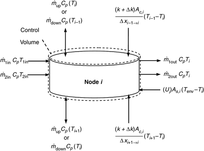
The time–temperature history of a node can be predicted by performing an energy balance on each storage section, accounting for thermal losses to the surroundings and the influence of adjacent nodes (e.g., mass and energy flows, including conduction between the layers and vertical conduction through the tank walls (Fig. 15.2).
image
Figure 15.2 Control volume used to define the flow of mass into and out of node i where 1 < i < N [15].
In Fig. 15.2, m˙upimage and m˙downimage are the fluid flow rates up and down the tank, respectively; Ac,i and As,i are the cross-sectional and surface area of node i, respectively; k and ∆k are tank fluid thermal conductivity and destratification conductivity (used to model destratification due to mixing at node interfaces and conduction along the tank wall) [6], respectively; Cp is the specific heat of the tank fluid; Ui is the node heat loss coefficient per unit area; m˙1inimage, m˙1outimage, m˙2inimage, and m˙2outimage are the mass flow rates of entering and exiting fluids 1 and 2, respectively; Ti+1, Ti, Ti–1, T1in, T2in, and Tenv are the temperatures located below, at, and above node i, the temperature of the entering fluid 1 and the entering fluid 2, and the temperature of the environment, respectively; and xi+1iimage and xi1iimage are the center-to-center distance between node i and the node below and above it, respectively.
To estimate the temperature distribution and the heat loss characteristics of the vertical tank the energy and mass flows into and out of each storage node from adjacent nodes are estimated based on the node temperatures that existed at the beginning of the time step (Fig. 15.2). Any temperature inversions that result from these flows are eliminated by mixing appropriate nodes at the end of each time step [12]. To solve for the temperature distribution in the storage tank a set of N first-order, ordinary differential equations resulting from each node’s energy balance [6] can be assembled, for example, an energy balance written about the ith tank node.
As the temperature of each node depends on the temperatures of the adjacent nodes and the temperature of the environment, it is necessary to simultaneously solve the system of equations. Computational efficiency and speed are therefore important, as an annual simulation may involve 200 000 time steps. In computer simulation programs (e.g., TRNSYS [13]), it is common practice to use standard numerical techniques to solve for the temperature distribution at each time step [6]. It has also been noted that simple storage models rapidly become more complicated as multiple inlet and outlet ports are added or auxiliary elements are placed in a storage tank [6,19]. As such, a number of variations have been introduced in current models, to better accommodate issues such as variable storage volumes, plume entrainment [5], and draw-off mixing [12]. Using a simple one-dimensional model as described earlier, it should be noted that the accuracy of the model relies on a number of assumptions being met. These are:
1. the flow of liquid within the tank is one-dimensional
2. the temperature and density of the fluid in each node is uniform and constant over the time step
3. the fluid streams from each node are considered fully mixed before they enter an adjacent node
4. the heat loss to the exterior of the tank and conduction in the tank walls are low enough that two- or three-dimensional temperature gradients do not form, promoting convection and de-stratification
5. the fluid velocities entering and exiting the storage tank are low enough that they do not promote extensive mixing within the storage tanks.
Not all of these assumptions are fully met in all real storages. For example, Shyu et al. [20] found that stratification decayed in a tank more rapidly than predicted for the theoretical rate when using the conductivity of water. The main reason for this is that the thermal conductivity of the wall material is typically higher than the conductivity of the water and this can promote convection motion along the wall and destratification within the tank. Given this, Shyu et al. [20] computed a table of “effective” conductivity values for various walls and insulation thicknesses to serve as a starting point for users.

4. Second Law analysis of thermal energy storage

While application of the First Law of Thermodynamics enables the determination of energy stored during a process (and the amount lost to the surroundings), the Second Law of Thermodynamics provides a mechanism for quantifying any degradation in the “usefulness” of the energy that occurs during the storing process [21]. To accomplish this, both exergy level and exergy efficiency have been widely used to evaluate the performance of TES systems [4]. Most recently, a study was conducted to examine the stored exergy of a stratified modular storage system when subjected to various charge and discharge strategies [15,22].
Traditionally, exergy is considered as a measure of the “quality” of energy or its potential to do work relative to a reference or dead state, usually representative of the surrounding conditions. Applying the First and Second Laws of Thermodynamics to a control volume with uniform properties the specific exergy of a substance, Ex, can be defined as:

Ex=(hh0)T0(ss0)

image
where h and s are the specific enthalpies and entropies of the substance at its current temperature and pressure, and h0 and s0 are its enthalpies and entropies at a reference state; T0 is the temperature of the reference state. It is highly desirable to develop TES systems that can store energy at its highest exergy level and to minimize the destruction of exergy associated with irreversible processes (i.e., entropy production). In a thermal storage, consisting of an effectively incompressible fluid (i.e., water), exergy destruction will primarily occur due to mixing and diffusion occurring during the charging, storage, and discharging processes. Exergy destruction during the storage of energy, over a period of time, occurs due to heat losses to the surroundings and the diffusion of heat through the fluid and the storage vessel. Exergy destruction also occurs during the charging and discharging of TES. Many indices have been proposed or are under development to quantify the Second Law performance of a TES system [23]; however, the performance of TES can be studied by observing the exergy level in the storage tank during the charging process. To avoid violating the First and Second Laws of Thermodynamics the maximum temperature in TES is determined by the maximum temperature occurring during the charge sequence. As such, high exergy will be achieved during charging if the bulk of the volume of the thermal storage can be brought as close as possible to the temperature of the charge fluid. In addition, higher degrees of temperature stratification in a storage should reduce exergy destruction associated with mixing and diffusion and are highly desirable in a storage. Therefore, to estimate the stored exergy values at any time t, (i.e., Extank(t)), within TES, values of exergy in each of the nodes within the storage tank are summed:

Extank(t)=node=1NExnode(t)

image

5. Solar thermal energy storage systems

Solar thermal energy systems have existed in a variety of forms for hundreds of years. The widespread use of solar energy to heat water for domestic consumption started in the early part of the 19th century; however, competition from low-cost fossil fuels reduced its popularity. It was not until the mid-1970s that it was reconsidered as an alternative to fossil- or nuclear-generated energy. During that period a number of configurations were developed in an effort to lower costs and improve performance. The developments that followed were often driven by local climatic, regulatory, and market conditions. As such, simple passive systems were developed for nonfreezing, hot climates and were widely used in the Mediterranean, Middle East, and Asia-Pacific regions. Different system approaches were used in Europe, Japan, North America, and Australia to produce systems that were freeze protected. However, virtually all systems include one or more solar collectors to capture and convert the Sun’s energy into heat, a storage tank to store the available energy until it is required, and a circulation system to move a heat transfer fluid between the collectors and the storage tank. A simple conceptual diagram of a solar hot water–heating system is shown in Fig. 15.3.
TES is an integral component of a solar hot-water system that may significantly improve its efficiency and cost effectiveness by allowing better utilization of the solar hardware and matching of the solar resource to the load. Most small- to medium-sized solar installations use diurnal storage, where energy is typically stored for 1 day or 2 days; however, weekly and seasonal storage is also used in certain applications. Primarily used to offset space heating loads, seasonal storage systems are designed to collect solar energy during the summer months and retain the heat in the storage for use during the winter months [24]. Characterized by their large capacity requirement (in the order of a hundred times the capacity of daily storage) [4], these systems typically run at a much higher cost and require a larger storage volume than short-term storages.
image
Figure 15.3 Simple solar hot water–heating system [15].
Much effort has been put into maximizing the performance of water storages and minimizing the cost of the storage vessels. Moreover, small hot-water heaters and storages (i.e., 180 and 270 L) have been produced in large quantity for the North American market and are readily available at low cost. Coupled to an external heat exchanger, they represent a cost-effective storage option for residential solar hot-water heaters. However, larger storage volumes in the range (500–1500) L are often required for multifamily residential units and small- to medium-sized commercial applications. Unfortunately, suitable storage vessels of this size are only produced in limited quantities, resulting in significantly higher costs per unit of storage volume [15]. In addition, these larger storage vessels are not well suited to retrofit situations where the storage vessel must be moved into a building space through existing door openings. Consequently, larger storages are often constructed onsite, and maintained at low pressure and vented to the atmosphere.
Finally, it has been shown that the thermal performance of water-based storage devices can be significantly improved by lowering the solar collector loop fluid flow rate, thus promoting an increase in thermal stratification in the storage tank(s) [1,10,25,26]. A study of “microflow” systems demonstrated that stratified storage delivered 37% more energy than a fully mixed storage of corresponding size [10]. This increase in efficiency can be attributed to two reasons: the low flow rate allows the hot water to enter and remain in a layer at the top of the tank thus allowing the energy in the tank to be available at a temperature that is closer to the desired load temperature; and, second, the resultant stratification allows cool fluid to circulate back to the solar collectors which increases the collector efficiency due to its lower inlet temperature [3]. In reality, the advantages of stratification will vary depending on the system configuration and distribution of the load throughout the day [27].

6. Cold thermal energy storage

Although sensible TES systems are predominantly used for space heating and domestic hot-water applications, cold thermal energy systems are becoming common. These systems are almost exclusively used in commercial and industrial applications as a method of shifting the energy consumption required for space cooling to the overnight period [28]. The ability to shift energy consumption to the overnight period can be beneficial for a number of reasons. The first and most significant is that most electrical jurisdictions in the world experience their peak electrical demand in the afternoon during the summer months. The ability to charge a cold TES system overnight and realize the cooling potential during the peak period helps reduce the peak load placed on the grid, and in turn could reduce the required electrical generating and transmission capacity required [29]. In addition to reducing the peak load the grid experiences, many power providers charge based on the demand, charging significantly higher electrical rates during peak periods in comparison with off-peak, overnight periods [29]. As such, a significant reduction in a building’s utility costs can also be realized through implementation of a cold thermal storage system. In addition to utility cost reductions, utilization of chiller equipment at night can see an increase in performance and capacity, as exterior heat rejection temperatures are much lower than those seen during the day [28]. This combined with using the thermal storage capacity to meet peak cooling demand allows for smaller capacity chillers to be installed.
Cold thermal storage is obtained almost exclusively using water or water–glycol solutions as the storage medium, due to the ease of obtaining these fluids and their low costs [4]. Additionally, they integrate into and operate with almost all standard chillers, so custom units are not required. The principal decision required when designing and specifying cold storage units is whether to use only sensible thermal storage, or whether the latent potential of the materials will be utilized. In essence, will the thermal storage contain only the storage medium as a liquid, or will the formation of ice in some capacity be introduced to the thermal storage system. There are many ways that ice can be introduced into the storage system, whether it be as slurry, ice balls, builtup ice on coils, or encapsulated ice cubes [28].
There are a number of factors that influence the decision as to whether to use sensible storage or a more complex system that incorporates PCM. The largest factors are storage capacity and storage density (the amount of energy that can be stored in a unit of volume). Due to the enthalpy of fusion for water being approximately 350 kJ kg–1 a single kilogram of water delivering cooling at 15 °C is able to store a total of 412.7 kJ of cooling potential. The mass of water using only sensible storage kept at 3 °C (small buffer to ensure freezing does not occur) and cooling at 15 °C is only capable of storing 50.2 kJ of cooling potential. From this simple example, it can be seen that ice storage stores over 8 times the cooling potential compared to a water storage system, and depending on the storage temperature and the required temperature for cooling, this can approach 20 times the capacity [4,21]. A third option is to store the cooling potential using a glycol solution. Glycol solutions have the benefit of a much lower freezing point; however, they also have a slightly lower heat capacity compared with water. This allows lower temperatures to be obtained without the risk of freezing, but does not require the complex systems required for ice storage. In this case a single kilogram of 50/50 glycol–water solution by volume with a storage temperature of –10 °C is able to store 92 kJ of energy. A graphical comparison of the energy density for cold storage can be seen in Fig. 15.4.
image
Figure 15.4 Storage energy density capacity of different cold thermal storage media.
Although energy storage density is much higher using ice storage the switch from sensible water storage to ice storage can have a negative effect on the performance of the refrigeration unit charging the thermal storage. This is caused by the fact that for water storage the evaporator temperature of the chiller is approximately 0 °C, while for an ice-based thermal storage system a colder evaporator temperature is required, typically –10 °C. At this reduced temperature, capacity drops to approximately 56% of that at 0 °C, while the coefficient of performance drops to 71% of that at 0 °C [4]. As a result, you typically use more energy and require a larger chiller to charge an ice storage system at the same rate as a water storage system making the capital purchase higher and increasing ongoing energy costs compared with the sensible storage system.
As a result of this degradation in performance at lower evaporator temperatures, ice storage should only typically be employed when the available space does not permit the use of sensible thermal storage due to lower storage density. In these cases a combination of sensible and latent storage can be employed, with the optimal combination found for building loads and usable space. Even with the degradation in performance, significant cost savings can be realized by building operators when incorporating cold thermal storage using either method.

7. Seasonal storage

While diurnal storage systems are designed to offset all or a portion of the daily heating and/or domestic hot-water demand, diurnal thermal storage has little to no effect on the seasonal performance of the heating system. Seasonal thermal storage systems meanwhile are used to meet the long-term, seasonal mismatch of available energy and energy demand. Seasonal TES is the storing of thermal energy, including heating or cooling potential, for the future long-term use of heating or cooling a building or for other extended periods of time [30]. When using ground source heat pump systems and solar thermal systems for space heating, often a thermal storage with an annual cycle time is required to maximize the energy efficiency and solar fraction of the system. The term solar fraction refers to the percentage of the overall load that is supplied by solar. The seasonal mismatch of energy availability and demand is the result of an overabundance of available heat, in the summer months, with little to no demand for use (with the exception of a small domestic hot-water requirement). Seasonal thermal storage systems allow for that excess heat to be collected when available in the summer months and stored for use over the winter period when heat is required [30]. Typically, this heat is collected from solar thermal collectors for storage or is the waste heat produced for air conditioning of buildings, as typically seen with ground source heat pump systems.

7.1. Applications

Solar thermal systems used for both space heating and domestic hot water are becoming more popular within the residential market; however, when using only diurnal storage these systems typically are unable to achieve solar fractions greater than 50% [31]. To increase the solar fraction of these systems a seasonal thermal storage system is required. When seasonal thermal storage systems are successfully implemented an annual solar fraction approaching 100% is obtainable [30]. To meet these high solar fractions, significant storage capacity is required, with seasonal thermal storage systems having a storage capacity typically between 100 and 1000 times greater per unit solar thermal collector than a diurnal thermal storage system [30]. Although storage capacities are significantly larger, solar thermal systems with seasonal storage systems typically have a capital cost double that of a similar system with only short-term storage [24].
Seasonal thermal storage is not only used with solar thermal heating systems, but is also commonly paired with heat pumps. Almost all liquid-to-liquid heat pump systems incorporate seasonal thermal storage, where source energy is extracted from the storage medium during the winter heating season and is converted to usable thermal energy by the heat pump. This energy can then be used either for space heating and/or domestic hot-water needs of a building. During the summer cooling period the waste heat from the air-conditioning process using the heat pump is deposited back into the seasonal storage medium, increasing its temperature and sensibly storing the heat for use in the reverse process during the winter [32].
Seasonal thermal storage systems are not only employed at the single dwelling or building level, but are now seeing widespread implementation at the community level. Particularly in Europe, however with some projects in North America), solar district heating systems are becoming more prevalent and in some districts can be cost competitive with traditional heating sources including gas [33]. Solar district heating is the heating of a central thermal storage system, with the heat collected being distributed as needed to dwellings within the community. Solar collectors can be centrally located, or distributed throughout the community, but all supply heat to the central system. District heating systems use the largest seasonal thermal storage systems currently employed and can be in excess of 40 000 m3 and contain in excess of 2000 m2 of solar thermal collectors. Due to economies of scale and the central nature of these systems, total capital cost is typically only (20–30)% of that compared with putting individual solar thermal systems in each house fed by the district heating system [24].

7.2. Storage Methods

Seasonal thermal storage can be achieved by a number of methods and using many different media. As a result of the large storage capacity required to meet seasonal storage demand, and the relatively low cost of materials used for sensible storage, seasonal thermal storage systems predominantly use sensible thermal storage methods; however, some seasonal storage systems do still employ chemical or phase change systems. The following sections will outline different sensible storage methods used for seasonal thermal storage.

7.2.1. Large-Scale Tanks

Water tanks are one of the most favorable methods for seasonal thermal storage systems due to the numerous benefits of using water as the thermal storage medium. Water, compared with many other sensible thermal storage media, has much higher heat capacity. Additionally, water has the benefit of being easily pumped, allowing for the charge and discharge of the systems by pumping hot water directly into the tank, or out of the tank to the end heating use [4]. Alternatively, the water used for thermal storage can be pumped into heat exchangers, where heat can be transferred to other transfer media, most commonly glycol solutions, used in solar thermal and other heating systems. The use of tanks with defined and well-designed shapes and aspect ratios means thermal stratification can be more easily achieved and the benefits previously discussed with respect to diurnal storage tanks can be realized in larger, seasonal storage tanks.
Typically, large-scale water tanks are used as seasonal thermal storage for a single house, or smaller groups of houses, where the tanks are small enough to be built offsite and then installed in place. This allows easy integration during the construction process and connects directly to the solar thermal collector system and the space heating system in the house. While most tanks are built offsite and installed a number of projects in Europe have been constructed using extremely large, buried seasonal thermal storage tanks. These tanks are typically built onsite using poured concrete lined with either a stainless steel or plastic-based liner to prevent vapor diffusion through the tank walls. The outside of the tank is then insulated using waterproof material, typically consisting of glass-based or polyurethane-based products. These include a 4 500 m3 tank in Hamburg and a 12 000 m3 tank in Friedrichshafen (both in Germany) [34]. Large-scale thermal storage tanks are more often used in a large district heating system as intermediate storage between much larger thermal storage systems and the solar collector system. This method is used in the Drake Landing Solar Community in Okotoks, Alberta (Canada) where two 120 m3 storage tanks are employed for short-term storage, between the borehole thermal energy system, the heating loads, and the solar thermal collector system installed throughout the community [35].
Seasonal thermal storage tanks are most commonly large, insulated cylindrical hot-water tanks with a vertical axis. The simplest and often the most inexpensive method for installing these tanks is to install them at ground level, with the tank projecting into the outdoor air. Although the simplest method a number of disadvantages exist. Most notably, with the tank exposed to ambient conditions, significant heat loss during the cold winter months is possible. To combat this heat loss, above-grade tanks must be well insulated, adding to the cost of installation. Additionally, above-grade tanks typically require larger pumps to overcome the hydraulic head present to pump the water into and out of the top of the tank, which can be significantly above the level of the equipment using the stored heat.
To combat many of the disadvantages associated with using an aboveground tank, one of the more popular methods for installing these tanks is to bury them. This method allows heat loss through the tank surface to the ambient air to be significantly reduced, as the ground temperature remains warmer through the winter months. This allows for a lower level of insulation requirement to achieve the same level of heat loss as the above-grade tanks. Additionally, this method provides the additional benefit allowing the space above the buried tank to be used (commonly a park or mechanical equipment is installed above the tank). When compared with an above-ground tank a buried tank is significantly more costly, with up to 30% of the total cost of the thermal storage system being the earth work required to excavate and bury the tank.
A third alternative, which is a hybrid of the two previous methods, involves the use of a bermed tank [36]. In this method the tank is partially buried, with the dirt removed to place the lower portion of the tank in the ground, then placed around the circumference of the tank and angled down toward the original grade line. This allows a larger portion of the tank to be either buried underground, or be soil backfilled, reducing heat loss from the tank and the insulation required to be installed. Additionally, it considerably lowers the height of the top of the tank in relation to the level grade and therefore decreases the pumping power required when compared with an aboveground tank (although still larger than required for a buried tank). The main benefit of using a bermed tank is that only minor excavation is required, and all the material remains onsite as the excavated material is used to create the berm around the tank. This significantly reduces the cost of the earth works to install the tank, and subsequently reduces the overall cost of the system.

7.2.2. Borehole Thermal Energy Storage

Borehole thermal energy storage (BTES) is one of the most common methods used for seasonal TES currently employed around the world. BTES involves using the ground as the storage medium, allowing heat to be added to the ground during the summer months, and extracted to meet the heating demands in the winter heating season. Boreholes are constructed by first drilling a hole to a depth ranging from (30 to 200) m in depth, depending on the ground conditions and composition [32]. Once the hole is drilled a U-tube heat exchanger is installed, which is a single pipe, typically made of polyethylene or high-density polyethylene, which is shaped into a U and inserted into the drilled hole. This allows the fluid to flow down to the bottom of the borehole and then return to the surface in a continuous loop. Once the piping is installed the remaining volume of the drilled borehole is filled with grout to provide structural support of the drilled hole and to increase thermal conductivity between heat transfer pipes and the ground. Although this is what is typically done in North America, water is commonly used as the filler material in European applications [37].
BTES can be implemented as a seasonal storage method for systems with a wide range of thermal capacities, from a single house right through to large-scale commercial buildings and district heating systems. The most common implementation of BTES systems is for the heating and cooling of individual residential houses, which is achieved by pairing BTES systems with a ground source heat pump. Typically, ground source heat pump BTES systems have a lower storage temperature and, as such, the heat from the ground cannot be used to directly heat the space or to meet the domestic hot-water demands of residents. As such, a heat pump is used to extract lower grade heat from the ground and transfer high-grade energy to the heat sink (e.g., house). During the summer cooling season, the heat pump is operated in reverse, extracting heat from the space and depositing it in the ground through the borehole. This process replenishes the heat in ground that has been extracted during the heating season and allows the heat to be stored for use in the next heating season. Ground source heat pumps are typically paired with one or two boreholes for residential use.
The use of seasonal BTES systems as part of large district heating systems and as a large-scale TES system for institutional and commercial applications are becoming increasingly popular. Unlike single residential systems that almost always require a heat pump to upgrade the energy stored in the ground, large-scale BTES can be used with a heat pump or as a standalone sensible thermal storage system, with the heat supplied by a large array of solar thermal collectors [32]. The size of the borehole thermal storage system can vary considerably based on the ground conditions, heating and domestic hot-water loads of the buildings or community, and the amount of energy required to be stored. Before these large-scale projects can be realized, ground testing to determine thermal conductivity and capacitance must be completed. The data obtained from these exploratory tests must then be implemented into detailed models of seasonal thermal storage systems, as well as the heat source (typically solar thermal collectors or industrial waste heat), heat pumps, and buildings to accurately obtain building loads. This completed model is then used to optimize the number and depth of the boreholes required to optimize the complete system.
Boreholes have been successfully used in many projects around the world in a number of different configurations. One of the most successful is the recently completed Drake Landing Solar Community previously mentioned [35]. This community, serviced by a district-heating system, contains 52 single detached homes, and achieves a heating solar fraction of in excess of 90% (meaning 90% of the heating demand is met using energy collected from the Sun). The community uses 800 solar thermal panels attached to the roofs of detached garages. These panels have a peak thermal production of 1.5 MW, which is fed into a central thermal storage system. The thermal storage system contains a short-term storage system consisting of a large water tank and a large BTES system used for long-term seasonal storage. The BTES contains 144 boreholes, each drilled to a depth of 37 m and spaced at 2.25 m on center. The system operates with 24 strings of 6 boreholes in series to maximize heat distribution within the system. The entire system has a total diameter of 35 m and the top is covered in insulation, a waterproof membrane, and then landscaped as a park to be used by members of the community. The BTES reaches temperatures in excess of 80 °C at the end of the summer months, and is then slowly released through the heating season through a district-heating network [38].

7.2.3. Aquifers

Aquifers are a method of storing thermal energy that uses naturally occurring groundwater as the storage medium. Aquifers are used predominately in Europe where their popularity has risen over the past few years. Using the Netherlands as an example, in 1995 only 29 aquifer thermal storage systems were operating, while in 2012 over 1800 systems were operating [39]. Aquifer storage systems come in many forms and configurations based on the desired system type and the ground properties of the proposed location. In general, aquifers can be either open or closed systems.
As an open system, groundwater, typically at temperatures which are significantly warmer than the outdoor ambient temperatures in the cold heating season, is used as a thermal energy source for heat pump systems. Groundwater is pumped out of the ground through a drilled well, passes through a heat exchanger with the heat pump, and then is dumped at the surface level, typically into a surface body of water [40]. Although this method uses groundwater as a thermal source, it is not a true thermal storage as it only removes energy from the ground, but does not actively replenish the energy removed, relying on the abundance of thermal energy present in the ground.
When using groundwater and aquifer thermal storage, a closed circuit is formed where water is pumped out of the ground, utilized in a heating or cooling process, and then returned to the ground. Heat is extracted during the heating season and then returned to the ground during the cooling season, replenishing the thermal energy available. Typical aquifer systems can be up to 200 m in depth and operate at relatively low temperatures, typical temperatures peaking at 20 °C and going as low as 5 °C when all energy is extracted [41]. As a result of the low operating temperatures, aquifer storage must be used in conjunction with a heat pump as the raw heat will not provide adequate heating.
Aquifer TES can be realized using two different configurations, with the appropriate method determined by the properties of the groundwater present at the site of installation. When groundwater flows a continuous regime is typically employed. Using this design, two wells are drilled, with one upstream of the second. Water is always extracted from the downstream well and returned upstream. This allows for a relatively constant temperature to be maintained throughout the year and has limited impact on groundwater properties. This method is much simpler in terms of control and piping installation; however, it has limited applications as the temperature remains relatively constant and there is almost no temperature difference between the two wells [40].
The more common arrangement is using a cyclic regime, where two wells are again used; however, they must be isolated from each other, meaning they are not fed by the same water mass. One well is used as hot storage and the second well maintained as cold thermal storage. During the heating season, heat is extracted from the hot well, used as the heat source for a heat pump, and the cold fluid deposited into the cold-side well. During the cooling season, cool water is used to extract heat using a heat pump and the hot fluid is deposited into the hot-side well. This works back and forth season to season, removing heat from one well and replenishing the thermal energy in the second well [40].

7.2.4. Rock-bed Thermal Energy Storage

Rock-bed thermal storage systems use rock as the storage medium, either as packed rock bed, small pebbles, or bricks. This storage method has a number of advantages when compared with other methods. These include the ability to operate at higher temperatures than other thermal storage methods, the systems require no drilling and can use air as the heat transfer fluid, reducing the costs associated with piping for fluids. Although some logistical benefits exist, packed rock-beds and pebble storage systems have a much lower energy density than water-based storage systems. As a result, to store the same amount of energy, a rock-based storage system must have a volume approximately three times greater than a water-based system, resulting in most seasonal rock-bed thermal storage systems having an immense volume (demonstration projects have been completed with rock-bed thermal storage systems in excess of 8000 m3) [34].
One method being used to reduce the volume required is the hybrid gravel/water storage system. This is a compromise between the high initial capital costs of a large-scale water tank and the low cost and low energy storage capacity of rock-bed thermal storage systems [34]. When designing the system the required volume is determined through simulation based on the heating and cooling loads of the building, the heating method, and consequently the storage temperature (direct from the rock bed or incorporating a heat pump), and the desired portion of the load to be met by TES. In addition to determining the size of the storage the size of the individual rocks or pebbles is also significant. The smaller the rock size the more densely the rock bed is packed and the less free space present for the heat transfer fluid to pass through. The smaller the spaces between the rocks the greater the stratification that can be realized within the rock bed [42]. This allows for better system efficiencies as the top is much warmer to better meet the heating demand while the bottom remains cooler, allowing cooler return temperatures to the heating source.

8. Concluding remarks

To make efficient use of a time-dependent source of energy, it is often necessary to store energy until it can be used to supply a particular load. For example, a storage system is particularly important for solar thermal systems as the availability of the solar resource varies over the day and season. To reduce cost and space requirements, thermal storages must have sufficient energy density, low energy losses, and efficient charge and discharge characteristics. To arrive at an efficient storage configuration for a particular application, it is necessary to conduct a detailed analysis of the thermodynamics, heat transfer, and fluid dynamics associated with that application.
Today, TES is considered an advanced energy technology [4]. Given the need to reduce greenhouse gas emissions and the increasing volatility of fossil fuels, the necessity to reduce energy consumption for heating and cooling becomes obvious. The use of thermal storage can alleviate the temporal energy mismatch between off-peak periods and building occupant demands (such as space conditioning and hot-water loads) by allowing energy to be stored, thus realizing significant energy savings and reducing the demand on fossil fuels during peak periods.

References

[1] Lavan Z, Thompson J. Experimental study of thermally stratified hot water storage tanks. Sol Energy. 1977;19:519524.

[2] Hahne E, Chen Y. Numerical study of flow and heat transfer characteristics in hot water stores. Sol Energy. 1998;64:918.

[3] Duffie JA, Beckman WA. Solar engineering of thermal processes. New York: John Wiley & Sons; 2013.

[4] Dincer I, Rosen M. Thermal energy storage; systems and applications, 2nd ed. Chichester, UK: John Wiley and Sons; 2011.

[5] Lightstone MF, Hollands KGT, Hassani AV. The effect of plume entrainment in the storage tank on calculated system performance. In: Proceedings of Solar Energy Society of Canada Inc., Ottawa, ON; 1988.

[6] Newton B. Modeling of solar storage sanks. M.Sc. thesis. Department of Mechanical Engineering, University of Wisconsin-Madison; 1995.

[7] Davidson JH, Adams DA. Fabric stratification manifolds for solar water heating. ASME J Sol Energy Eng. 1994;116:130136.

[8] Shah LJ, Andersen E, Furbo S. Theoretical and experimental investigation of inlet stratifiers for solar storage tanks. Appl Therm Eng. 2005;25:20862099.

[9] Andersen E, Furbo S, Fan J. Multilayer fabric stratification pipes for solar tanks. Sol Energy. 2007;81:12191226.

[10] Hollands KGT, Lightstone M. A review of low flow, stratified tank solar water heating systems. Sol Energy. 1989;43:97105.

[11] Hess CF, Miller CW. An experiment and numerical study on the effect of the wall in a thermocline type cylindrical enclosure. Sol Energy. 1982;28:145152.

[12] Kleinbach EM, Beckman WA, Klein SA. Performance study of one dimensional models for stratified thermal storage tanks. Sol Energy. 1993;50:155166.

[13] TRNSYS: a transient simulation program. Madison, WI: University of Wisconsin Solar Energy Laboratory; 2015.

[14] Nizami DJ, Lightstone MF, Harrison SJ, Cruickshank CA. Simulation of the interaction of a solar domestic hot water tank system with a compact heat exchanger. In: Proceedings of the Joint Conference of the Canadian Solar Building Research Network and the Solar Energy Society of Canada Inc., Fredericton, New Brunswick; 2008: p. 24–29.

[15] Cruickshank CA. Evaluation of a stratified multi-tank thermal storage for solar heating applications. Ph.D. thesis. Department of Mechanical and Materials Engineering, Queen’s University, Kingston, ON, Canada; 2009.

[16] Cruickshank CA, Harrison SJ. Heat loss characteristics for a typical solar domestic hot water storage. Energy Buildings. 2010;42:17031710.

[17] Mather DW, Hollands KGT, Wright JL. Single- and multi-tank energy storage for solar heating systems: fundamentals. Sol Energy. 2002;73:313.

[18] Cruickshank CA, Harrison SJ. Simulation and testing of stratified multi-tank, thermal storages for solar heating systems. Proceedings of the EuroSun 2006 Conference, Glasgow, Scotland, UK; 2006.

[19] Lightstone MF, Raithby GD, Hollands KGT. Numerical simulation of the charging of liquid storage tanks: comparison with experiment. ASME J Sol Energy Eng. 1989;111:225231.

[20] Shyu RJ, Lin JY, Fan LJ. Thermal analysis of stratified tanks. ASME J Sol Energy Eng. 1989;111:5561.

[21] Moran M, Shapiro H. Fundamentals of engineering thermodynamics. 6th ed. New York: John Wiley & Sons; 2008.

[22] Dickinson RM, Cruickshank CA. Exergy analysis of a multi-tank thermal storage for solar heating applications. Int J Exergy. 2014;15:412428.

[23] Haller MY, Cruickshank CA, Streicher W, Harrison SJ, Andersen E, Furbo S. Methods to determine stratification efficiency of thermal energy storage process – review and theoretical comparison. Sol Energy. 2009;83:18471860.

[24] Fisch MN, Guigas M, Dalenback JO. A review of large-scale solar heating systems in Europe. Sol Energy. 1998;63:355366.

[25] Phillips WF, Dave RN. Effects of stratification on the performance of liquid-based solar heating systems. Sol Energy. 1982;29:111120.

[26] Cristofari C, Notton G, Poggi P, Louche A. Influence of the flow rate and the tank stratification degree on the performance of a solar flat-plate collector. Int J Therm Sci. 2003;42:455469.

[27] Rosengarten G, Morrison G, Behnia M. A second law approach to characterizing thermally stratified hot water storage with application to solar water heaters. ASME J Sol Energy Eng. 1999;121:194200.

[28] Yau Y, Rismanchi B. A review on cool thermal storage technologies and operating strategies. Renew Sust Energy Rev. 2012;16:787797.

[29] Ontario Ministry of Energy. Achieving balance—Ontario’s long term energy plan. Toronto, ON: Ontario Ministry of Energy; 2013. p. 1–13.

[30] Pinel P, Cruickshank CA, Beausoleil-Morrison I, Wills A. A review of available methods for seasonal storage of solar thermal energy in residential applications. Renew Sust Energy Rev. 2011;15:33413359.

[31] Edwards S. Sensitivity analysis of two solar combisystems using newly developed hot water draw profiles—M.A.Sc. thesis. Carleton University, Ottawa, ON; 2014.

[32] Gao L, Zhao J, Tang Z. A review on borehole seasonal solar thermal energy storage. Energy Procedia. 2015;70:209218.

[33] Flynn C, Siren K. Influence of location and design on the performance of a solar district heating system equipped with borehole seasonal storage. Renew Energy. 2015;81:377388.

[34] Xu J, Wang RZ, Li Y. A review of available technologies for seasonal thermal energy storage. Sol Energy. 2014;103:610638.

[35] Sibbitt B, McClenahan D, Djebbar R, Thornton J, Wong B, Carriere J, Kokko J. Measured and simulated performance of a high solar fraction district heating system with seasonal storage. In: Proceedings of the ISES Solar World Congress, Kassel, Germany; 2011.

[36] Rosen MA. The use of berms in thermal energy storage systems: energy-economic analysis. Sol Energy. 1998;63:6978.

[37] Kizilkan O, Dincer I. Borehole thermal energy storage system for heating applications: thermodynamic performance assessment. Energy Convers Manage. 2015;90:5361.

[38] Drake Landing Solar Community. http://www.dlsc.ca/

[39] Possemiers M, Huysmans M, Batelaan O. Influence of aquifer thermal energy storage on groundwater quality: a review illustrated by seven case studies in Belgium. J Hydrol: Regional Studies. 2014;2:2034.

[40] Lee KS. Underground thermal energy storage. Seoul, South Korea: Springer; 2013.

[41] Zeghici RM, Essink G, Hatog N. Integrated assessment of variable density–viscosity groundwater flow for a high temperature mono-well aquifer thermal energy storage (HT-ATES) system in a geothermal reservoir. Geothermics. 2015;55:5868.

[42] Singh H, Saini RP, Saini JS. Performance of packed bed solar energy storage system having large sized elements with low void fraction. Sol Energy. 2013;87:2234.

..................Content has been hidden....................

You can't read the all page of ebook, please click here login for view all page.
Reset