
The Future in Nuclear Power
Perceptions of nuclear power tend to be dominated by concerns on safety and waste management, and the key to understanding how these can be handled with security and sustainability is a fundamental understanding of nuclear processes and materials. This chapter traverses the chapters from atomic-level nuclear changes, to reactor options, and finally the handling of spent nuclear fuel. A comprehensive understanding leads to comprehensive solutions that are sustainable.
Keywords
Beta particle; neutron; atom; radiation; fission; reactor; isotope
Shortly before World War II the physics research community learned that the uranium-235 isotope would fission when exposed to a beam of neutrons. When a uranium nucleus split a huge surge of energy and two or three neutrons were released. The potential use of these data indicated it would be possible to assemble a powerful explosive weapon. All of the research that led to the production of the two nuclear bombs that exploded over Hiroshima and Nagasaki Japan was labeled “top secret.” This ended World War II with the surrender of Japan.
There were lots of freight shipped during World War II and the German submarines were a plague—sinking a high percentage of the Allied surface vessels. Submarines used diesel electric generators to charge their batteries that allowed them to cruise underwater using stored electric power. A submarine had to come close to the surface so that the diesel engines could “breathe” to charge the batteries. This signaled their location. Admiral Hyman Rickover was assigned the task of “taming” the nuclear fission process to produce energy to charge the submarine batteries while they were under water. This made the Nuclear Navy possible with submarines cruising under water—undetected for 90 of more days.
Civilian contractors building submarines made their living building coal-fired electric power plants. There was a Federal “Atoms for Peace Initiative” that made a perfect fit for using the submarine nuclear power plant as the staring model for civilian nuclear power plants. The secrets for this application were suspended and civilian nuclear power was launched. This chapter presents some details of this effort and includes some proposals pointing to the future of civilian nuclear energy.
Energies of Nuclear Processes
The huge quantities of energy liberated in nuclear power plants come from the nuclei of atoms. In the fission process, relatively stable nuclei are induced into excited states that fission and release energy as they form new smaller stable atom nuclei. The heat produced in the nuclear reactor is converted to work through a heat engine power cycle.
The natural stability of atoms is characterized by their half-life. The half-life of U-238 is 4.5×10⁹ years. If 1 pound of pure U-238 were flying through outer space today, in 4.5 billion years that meteor would have a total mass slightly less than 1 pound—one half pound would be U-238 and the other half would be fission products, mostly lead. Since the earth is about 5 billion years old, the U-238 present on earth today is about half of that present when earth was formed.
While the atomic stability is typically discussed in relative rather than absolute terms, atoms with half-life greater than 4.5 billion years are generally considered stable. Lead (Pb-206) is stable; the change in concentration of a 1-pound lead meteor would be negligible over a 4.5-billion-year period.
The decay of U-238 is a natural process (specifically, an α-decay process1). An unnatural decay of a nucleus, nuclear fission can be induced by collision with a neutron. A nuclear reactor environment is designed to sustain a critical concentration of free neutrons that gives a constant and controlled source of heat from induced fission. U-235 is the isotope that provides most of the energy nuclear reactor. Figure 8.1 illustrates the overall process by which U-235 releases heat through neutron-induced fission.

The energies released from the excited nuclei are not common in nature. However, analogous electron processes are regularly observed. For example, an incandescent light bulb operates on the principle of using electric power to increase the energy of the metal filament (high temperature)—some of this energy produces excited states of the electrons that surround the metal nuclei. These excited electron states emit visible radiation (light) as they return to lower energy, more stable states or ground states.
Table 8.1 provides several example emissions that occur when electrons and nuclei go from excited states to ground states (referred to as stable states for nuclei)—electrons and nuclei have multiple excited states and one or two stable/ground states. The energies are reported in electron volts; one electron volt is equivalent to 1.602×10⁻¹⁹ joules or 1.18×10⁻¹⁹ foot pounds.
Table 8.1
Examples of different emissions from nuclei and electrons
| Type of emission | Source | Energy level |
| Nuclear | ||
| Beta | Atomic decay in nuclear reactor | Disintegration energy of S-38—2.94 MeV |
| Alpha | Atomic decay in nuclear reactor | — |
| Neutron | Atomic decay in nuclear reactor | Fission release—~2 MeV |
| Fast neutron—>1 MeV | ||
| Thermal neutron—0.025 eV | ||
| γ-ray | Nuclear transition from excited state to lower energy state | Relaxing of excited states of Ni-60—1.174, 2.158, and 1.332 MeV |
| U-234 decay to Th-230—0.068 MeV | ||
| Electron | ||
| X-ray | Typically from 5–100,000 eV | |
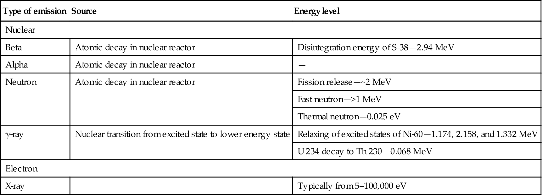
Among the lowest energy emissions from electrons is visible light resulting from electricity flowing through an incandescent light bulb. Among the highest energy emissions are neutrons emitted as part of atomic decay (2,000,000 eV). As illustrated by the comparison of Table 8.2, the energies associated with atomic processes are much larger than electron processes; atomic processes tend to be useful in large power plants while electronic processes tend to have applications in homes and offices.
Table 8.2
Examples of energy levels in electron volts for different processes
| Other processes | |
| U-235 fission to Rb-93+Cs-140 | 200 MeV |
| Ionization | Remove outer electron from lead—7.38 eV |
| Remove inner electron from lead—88,000 eV | |
| Mass defect | Mass defect of Li-7—931.5 MeV |
| Binding energy | Binding energy of Li-7—1784 MeV |

Electron emissions tend to be photonic (light, energetic x-rays); nuclear emissions may be photonic (γ-rays) or have white particle mass (α, β, and neutron) as energy components.
Of the emissions in Table 8.1, only the neutrons can collide and combine with an atom nucleus—often leading to an unstable state of the nucleus. In some physics laboratories atomic accelerators are able to increase the energy of particles that collide to produce excited nuclei or new elements.
If neutron loses enough energy through collisions, it will at sufficiently low energy convert to atomic hydrogen (one proton and one electron). Beta (β) particles become electrons, and alpha (α) particles become helium (He-4). These transitions are summarized in Table 8.3.
Table 8.3
While electronic emissions dissipate, nuclear emissions do not dissipate
| Type of emission | Product of emission |
| Nuclear | |
| Beta | Is newly produced, excited electron |
| Alpha | Is newly produced, excited helium atom nucleus |
| Neutron | Is newly produced, excited atomic hydrogen (but remains a neutron if incorporated into another nucleus) |

The US Department of Energy publication entitled DOE Fundamentals Handbook, Nuclear Physics and Reactor Theory, Volume 1 of 2 [1] provides a detailed summary of key aspects of nuclear physics including the following excerpts (italics) that describe nuclides, nuclear stability, and conventions for reporting the atomic information.
Chart of the Nuclides
A tabulated chart called the Chart of the Nuclides lists the stable and unstable nuclides in addition to pertinent information about each one. Figure 8.2 shows a small portion of a typical chart. This chart plots a box for each individual nuclide, with the number of protons (Z) on the vertical axis and the number of neutrons (N=A–Z) on the horizontal axis.

The completely gray squares indicate stable isotopes. Those in white squares are artificially radioactive, meaning that they are produced by artificial techniques and do not occur naturally. By consulting a complete chart, other types of isotopes can be found, such as naturally occurring radioactive types (but none are found in the region of the chart that is illustrated in Figure 8.2).
Located in the box on the far left of each horizontal row is general information about the element. The box contains the chemical symbol of the element in addition to the average atomic weight of the naturally occurring substance and the average thermal neutron absorption cross section, which will be discussed in a later module. The known isotopes (elements with the same atomic number Z, but different mass number A) of each element are listed to the right.
Information for Stable Nuclides
For the stable isotopes, in addition to the symbol and the atomic mass number, the number percentage of each isotope in the naturally occurring element is listed, as well as the thermal neutron activation cross section and the mass in atomic mass units (amu). A typical block for a stable nuclide from the Chart of the Nuclides is shown in Figure 8.3.

Information for Unstable Nuclides
For unstable isotopes the additional information includes the half-life, the mode of decay (for example, β−, α), the total disintegration energy in MeVTable (million electron volts), and the mass in amu when available. A typical block for an unstable nuclide from the Chart of the Nuclides is shown in Figure 8.4.

Neutron–Proton Ratios
Figure 8.5 shows the distribution of the stable nuclides plotted on the same axes as the Chart of the Nuclides—it provides the skeleton of the complete Chart of Nuclides. As the mass numbers become higher, the ratio of neutrons to protons in the nucleus becomes larger. For helium-4 (2 protons and 2 neutrons) and oxygen-16 (8 protons and 8 neutrons) this ratio is unity. For indium-115 (49 protons and 66 neutrons) the ratio of neutrons to protons has increased to 1.35, and for uranium-238 (92 protons and 146 neutrons) the neutron-to-proton ratio is 1.59.

If a heavy nucleus were to split into two fragments, each fragment would form a nucleus that would have approximately the same neutron-to-proton ratio as the heavy nucleus. This high neutron-to-proton ratio places the fragments below and to the right of the stability curve displayed by Figure 8.5. The instability caused by the excess of neutrons is generally rectified by successive beta emissions, each of which converts a neutron to a proton and moves the nucleus toward a more stable neutron-to-proton ratio.
Careful measurements have shown that the mass of a particular atom is always slightly less than the sum of the masses of the individual neutrons, protons, and electrons of which the atom consists. The difference between the mass of the atom and the sum of the masses of its parts is called the mass defect (Δm).
The loss in mass, or mass defect, is due to the conversion of mass to binding energy when the nucleus is formed. Binding energy is defined as the amount of energy that must be supplied to a nucleus to completely separate its nuclear particles (nucleons). It can also be understood as the amount of energy that would be released if the nucleus was formed from the separate particles. Binding energy is the energy equivalent of the mass defect. Since the mass defect was converted to binding energy (BE) when the nucleus was formed, it is possible to calculate the binding energy using a conversion factor derived by the mass-energy relationship from Einstein’s Theory of Relativity.
Energy Levels of Atoms
The electrons that circle the nucleus move in fairly well defined orbits. Some of these electrons are more tightly bound in the atom than others. For example, only 7.38 eV is required to remove the outermost electron from a lead atom, while 88,000 eV is required to remove the innermost electron. The process of removing an electron from an atom is called ionization, and the energy required to remove the electron is called the ionization energy.
In a neutral atom (number of electrons=Z) it is possible for the electrons to be in a variety of different orbits, each with a different energy level. The state of lowest energy is the one in which the atom is normally found and is called the ground state. When the atom possesses more energy than its ground state energy, it is said to be in an excited state.
An atom cannot stay in the excited state for an indefinite period of time. An excited atom will eventually transition to either a lower-energy excited state, or directly to its ground state, by emitting a discrete bundle of electromagnetic energy called an x-ray. The energy of the x-ray will be equal to the difference between the energy levels of the atom and will typically range from several eV to 100,000 eV in magnitude.
Energy Levels of the Nucleus
The nucleons in the nucleus of an atom, like the electrons that circle the nucleus, exist in shells that correspond to energy states. The energy shells of the nucleus are less defined and less understood than those of the electrons. There is a state of lowest energy (the ground state) and discrete possible excited states for a nucleus. Where the discrete energy states for the electrons of an atom are measured in eV or keV, the (k=1000) energy levels of the nucleus are considerably greater and typically measured in MeV (M=1,000,000).
A nucleus that is in the excited state will not remain at that energy level for an indefinite period. Like the electrons in an excited atom, the nucleons in an excited nucleus will transition towards their lowest energy configuration and in doing so emit a discrete bundle of electromagnetic radiation called a gamma ray (γ-ray). The only differences between x-rays and γ-rays are their energy levels and whether they are emitted from the electron shell or from the nucleus. The ground state and the excited states of a nucleus can be depicted in a nuclear energy-level diagram. The nuclear energy-level diagram consists of a stack of horizontal bars, one bar for each of the excited states of the nucleus. The vertical distance between the bar representing an excited state and the bar representing the ground state is proportional to the energy level of the excited state with respect to the ground state. This difference in energy between the ground state and the excited state is called the excitation energy of the excited state. The ground state of a nuclide has zero excitation energy. The bars for the excited states are labeled with their respective energy levels. Figure 8.6 is the energy level diagram for nickel-60.

Stability of Nuclei
As mass numbers become larger, the ratio of neutrons to protons in the nucleus becomes larger for the stable nuclei. Non-stable nuclei may have an excess or deficiency of neutrons and undergo a transformation process known as beta (β) decay. Non-stable nuclei can also undergo a variety of other processes such as alpha (α) or neutron (n) decay. As a result of these decay processes, the final nucleus is in a more stable or more tightly bound configuration.
Natural Radioactivity
In 1896, the French physicist Becquerel discovered that crystals of a uranium salt emitted rays that were similar to x-rays in that they were highly penetrating, could affect a photographic plate, and induced electrical conductivity in gases. Becquerel’s discovery was followed in 1898 by the identification of two other radioactive elements, polonium and radium, by Pierre and Marie Curie.
Heavy elements, such as uranium or thorium, and their unstable decay chain elements emit radiation in their naturally occurring state. Uranium and thorium, present since their creation at the beginning of geological time, have an extremely slow rate of decay. All naturally occurring nuclides with atomic numbers greater than 82 are radioactive. X
Nuclear Decay
Table 8.4 provides examples of different types of nuclear transitions. These transitions can be from a highly unstable nucleus or from a relatively stable nucleus. A highly unstable nucleus has a short half-life (time in which the concentration of that isotope is reduced by 50% due to atomic transition) while stable molecules have long half-lives.
Table 8.4
Example notations of nuclear processes
| Process | Formula | Description [1] |
| Alpha decay | KE is kinetic energy of the α-particle is helium nucleus | |
| Beta decay | Neutron converted to proton | |
| ν represents a neutrino—interacts little with atoms and escapes at speed of light | ||
| Beta decay | Proton converted to neutron through positron formation | |
| Electron capture | Proton is converted to neutron by electron capture |

During and immediately after the burn of a nuclear fuel rod, radiation levels are very high due to the large number of radio nuclides with short half-lives. By definition, these short half-life nuclei rapidly undergo nuclear transitions. For a given nuclei, this process continues in a decay chain until a molecule with a stable or long-half-life nucleus is formed. The following decay of rubidium-91 to zirconium 91 illustrates a decay chain. The numbers under the arrows indicate half-lives in seconds, hours, days, and years.
These decay chains are important when treating fission products. The short-lived products will rapidly decay. If spent fuel is stored for 30 years at the nuclear power plant, this time will reduce the concentration of all nuclides with half-lives less than 3 years to a concentration less than 0.1% of the initial concentration.
Fortunately, the majority of the short-lived isotopes decay to stable nuclides. About 10% of the fission products remains as high-level waste after 30 years of storage—the remainder have decayed to stable nuclides.
Conditions for Successful Nuclear Fission
For nuclides to successfully undergo neutron-induced fission, a number of conditions must be met that are analogous to a chemical reaction. Table 8.5 summarizes and compares the factors that lead to fission with those conditions that promote chemical reactions.
Table 8.5
Factors impacting the rate of nuclear fission versus analogous factors for chemical reaction
| Factor | Nuclide | Chemical reagent |
| Materials must have a propensity to react | A low critical energy that corresponds to classifications as fissile or fissionable | A low activation energy |
| Materials must have ability to go to lower energy state | Products must have a higher binding energy | Products must have a lower Gibbs free energy |
| Degree of molecular excitement should be optimal | The energy of the neutron must be correct—high (fast) or low (thermal) energy level may be optimal | Temperature must be high enough to react but low enough to stabilize the products |
| Events must be concentrated rather than disperse | Concentrations of reacting materials (e.g., U-235) must be high enough to sustain reaction but not so high to run away (explode) | High concentrations are needed for reasonable reactor size, or a solvent must be used to avoid run away |
These topics are discussed in the following four sections.
(a) Uranium and Other Fertile Materials
A nuclear reactor is designed to provide a flux of neutrons with the right energy to provide a constant, steady rate of nuclear fission. Each U-235 yields about 200 MeV per atom of uranium that undergoes fission.
U-235 is referred to as a fissile material because U-235 will absorb a neutron with very low kinetic energy (referred to as thermal neutrons) and this produces fission. Table 8.6 summarizes the three types of materials that are of interest in nuclear fission fuels. Fissile atoms undergo fission because a neutron of low kinetic energy can induce fission.
Table 8.6
Definitions and examples of nuclear fission fuels
| Material category | Definition | Examples |
| Fissile | Nuclides for which fission is possible with neutrons of any energy level | U-235, U-233, and Pu-239 |
| Fissionable | Nuclides for which fission is possible with neutron collision | U-235, U-233, Pu-239 |
| Fertile | Materials that can absorb a neutron and become fissile materials | U-238 and Th-232 |
When a neutron combines with a stable nucleus, a binding energy (BE) corresponding to that neutron addition is released. When that BE is greater than a critical energy (specific to the nuclide before addition of the neutron), the nuclide can undergo fission. Table 8.7 provides the binding energies (MeV/nucleon) and critical energies of the five fissile and fissionable materials. Th-232 and U-238 are fissionable, but not fissile because it takes higher energy neutrons to bring sufficient kinetic energy so that the sum of kinetic and binding energies exceeds the “critical energy” producing fission.
Table 8.7
Critical energy versus energy released with absorption of additional neutron [1]
| Target nucleus | Critical energy Ecrit | Binding energy of last neutron BEn | BEn − Ecrit |
| Th-232 | 7.5 MeV | 5.4 MeV | −2.1 MeV |
| U-238 | 7.0 MeV | 5.5 MeV | −1.5 MeV |
| U-235 | 6.5 MeV | 6.8 MeV | ±0.3 MeV |
| U-233 | 6.0 MeV | 7.0 MeV | +1.0 MeV |
| Pu-239 | 5.0 MeV | 6.6 MeV | +1.6 MeV |

When U-238 or Th-232 absorb neutrons and fission does not occur, they can undergo the decay chain summarized in Figure 8.7 resulting in the formation of U-233 and Pu-239. U-238 and Th-232 are referred to as fertile materials because absorption of a neutron can produce a fissile material. Because of these nuclear processes, it is possible for a nuclear reactor to produce more fuel than is consumed—reactors designed to do this are called breeder reactors. In light water converter reactors (also referred to as burner reactors), that consume more fuel than is produced, about one-third of the energy produced is a result of Pu-239 production with subsequent Pu-239 fission. At the end of the nuclear fuel burn in a light water reactor about 0.9% Pu-239 remains in the fuel. The new fuel initially contained 3.4% U-235 (0% Pu-239).

The decay chains in Figure 8.7 (absorption without fission) are broadly referred to as transmutation processes. Transmutation is important for converting fertile fuel to fissile fuel. The susceptibility of materials to transmutation is covered in the next section under the topic of absorption cross section.
Transmutation is important for creating fissile materials and for converting problem radioactive wastes into more benign materials. Not all nuclides in nuclear waste present the same degree of waste handling problems. For example, nuclides with short half-lives (less than about 5 years) can be stored until the radioactive decay reaches benign levels. Wastes with very long half-lives tend to be less hazardous than the uranium mined to create the nuclear fuel. However, wastes with intermediate half-lives are more hazardous than natural ores. They take too long to decay in 30–60 years used for temporary storage. Transmutation can transmute some of these waste materials into new nuclides that decay quickly or that are stable.
(b) Binding Energy Constraints
Available technology limits sustainable fission power to fissionable materials originating from natural uranium and thorium. For fission to occur, the nuclei produced from the nuclear transformation must have a higher BE than the nuclei undergoing fission (see definition of BE). BE is defined so that higher binding energies represent more permanent nuclei. The most stable nuclei, like iron, have the highest binding energies.
The BE trends in Figure 8.8 illustrate that those nuclei with atomic weights greater than about 60 can undergo fission to produce more tightly bound nuclei. Nuclei with atomic weights less than about 60 can undergo fusion to produce more tightly bound nuclei.

The total energy release from the fission of U-235 is about 200 MeV. About 187 MeV of the energy is immediately released in the form of kinetic energy of the fission fragments, kinetic energy of the fission neutrons, and γ–rays. The excited product nuclei will release the remaining 13 MeV in the form of kinetic energy of delay beta particles and decay γ–rays. Table 8.8 reports average quantities of instantaneous and delayed energy release from U-235 fission by a thermal neutron. Of these emissions, the 10 MeV of energy from the neutrinos escape the reactor system.
Table 8.8
Instantaneous and delayed energy from fission [1]
| Instantaneous | |
| Kinetic energy of fission products | 167 MeV |
| Energy of fission neutrons | 5 MeV |
| Instantaneous γ-ray energy | 5 MeV |
| Capture γ-ray energy | 10 MeV |
| Total | 187 MeV |
| Delayed | |
| β-Particles form fission products | 7 MeV |
| γ-rays from fission products | 6 MeV |
| Neutrinos | 10 MeV |
| Total | 23 MeV |

(c) Nuclear Cross Sections
Nuclear cross sections are tabulated for atoms and characterize the susceptibility of the nuclide to interact with a neutron. Different representative cross sections are reported for different types of interaction. While fissile, fissionable, and fertile classifications indicate what happens if a neutron is absorbed by a nuclide, the cross section indicates the size of the target for neutron capture.
The cross sections are dependent on the energy of the neutron and the properties of the nuclide. These microscopic cross sections may be viewed as the area available for a neutron to hit to induce reaction. A larger cross section provides an increased probability for reaction.
Table 8.9 provides example nuclear cross sections for U-235 and U-238. Cross sections (reported in barns, 1 barn=10−24 cm2) for both fission and capture are provided. The thermal neutrons (<1 eV) typically have cross section 20–30 times larger than fast neutrons (1–2 MeV). It is this large cross section for U-235 and thermal neutrons that made it the fuel of choice for commercial nuclear reactors.
Table 8.9
Example cross section areas [2]
| Nuclide | Kinetic energy of neutron (eV) | Fission cross section (barns) | Capture cross section (barns) |
| U-235 | 0.5 | 50 | 7 |
| U-235 | 1,000,000 | 2 | 0.15 |
| U-238 | 0.5 | 0.6 | N/A |
| U-238 | 1,000,000 | 0.1 | 0.02 |

Fission and capture cross sections are two of the four cross sections that dominate nuclear reactor behavior. Table 8.10 illustrates these and includes elastic and inelastic cross sections.
Table 8.10
Illustration of prominent cross sections in nuclear reactors
| Process | Description [1] |
| Fission | 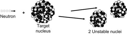 |
| Transmutation |  |
| Scattering (elastic) |  |
| Scattering (inelastic) |  |

The fission cross sections for U-235 is about 50 barns for the thermal neutron versus 2 barns for the fast neutron. For U-235 (fissile), the fission cross section is greater than the capture cross section, fission will occur more often than capture.
Fertile nuclides like U-238 have critical fission cross sections below a neutron energy level. The fission cross section for U-238 is equal to the capture cross section at 1.3 MeV. Higher energy neutrons will tend to cause fission while lower energy neutrons will tend to cause transmutation, the pathway to forming plutonium.
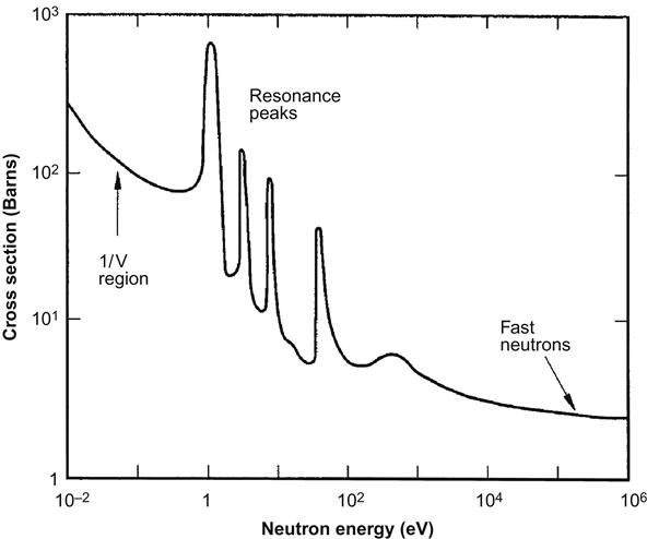
Fission, capture, scatter, and total cross sections are a few of the different types of cross sections that are characterized. Figure 8.9 shows a typical plot of total nuclear cross section area versus the energy level of the neutron. The complex nature of the free neutron interaction with nuclei goes beyond the scope of this text with much yet to be learned. Key points have been presented; especially important is the distinction between thermal neutrons (<1 eV) and fast neutrons (typically >1 MeV). The thermal neutron is key in propagating reactions in the Generation II nuclear reactors including current commercial light water reactors. For fast-spectrum reactors (the Generation IV designs) fast neutrons are key to the performance. Fast neutrons can directly induce fission in U-238 and can fission actinides.
Actinides are nuclides with atomic numbers between 89 and 104 (at an atomic number of 92, uranium is an actinide). Actinides such as plutonium (Pu), neptunium (Np), americium (Am), and curium (Cm) are formed in nuclear reactors (see Table 8.11). Once formed, they can continue absorbing thermal neutrons, eventually reducing the number of neutrons available to promote fission. Fast neutrons tend to produce fission. So, fast neutrons cause actinides to release fission energy (rather than inhibit other fission processes).
Table 8.11
Transuranic elements of primary interest to AFCI program including uranium as reference
 |
| Why does transuranic matter? [3] • Transuranic elements affect repository performance by dominating long-term heat load and long-term radiotoxicity. • Transuranic elements and enriched uranium are the only materials of concern for proliferation. • Transuranic elements can be destroyed while producing extra energy if recycled in (fast spectrum) nuclear reactors. |

Fast-spectrum reactors are important for sustainable nuclear power. Fast-spectrum reactors eliminate the need to separate the actinides when reprocessing nuclear fuel. This reduces the cost and promotes sustainable economics. Using all the actinides as fuel removes them from the waste stream and eliminates the long-term storage problem.
(d) Concentrated Events
Fissile materials U-235 and Pu-239, meet the constraints of fission and, release energy as they form smaller, more stable nuclei. The chain reaction is maintained by the neutron flux. The final components of the controlled release of the nuclear energy are the initiation of the neutron flux and maintaining the neutron flux. The neutron flux is the number of neutrons passing through an area of 1 sq. cm per second. Since the neutrons tend to be moving through solids (stopped or scattered only by the dense nuclei of the atoms in the solid), the energy of the neutrons decreases (they slow down) as they travel through the reactor core.
A discussion of materials for initiating the neutron flux is beyond the scope of this text. There are such materials that are used to start the reactor by initiating fission.
Sustaining the neutron flux is the most important criteria in nuclear reactor design. The neutron flux is depleted by neutron capture and by scattering out of the reactor core volume. The neutron poisons (boron as boric acid in the reactor cooling water) are used to maintain the neutron flux for constant energy production.
In a controlled reactor environment, the flow of neutrons (the neutron flux) achieves a steady state consistent with the desired heat (energy) release. This is achieved with the right concentration of U-235 or Pu-239 present—achieved by concentrating them in the fuel rods and proper spacing of the fuel rods. The right fuel rod concentration is typically between 2.6% and 4.0% U-235 in a light water reactor. Some of the proposed Generation IV designs may use concentrations up to 20%. The spacing of the fuel rods in the reactor and the fissile isotope concentration in the fuel provide the controlled release of energy. Since the medium (water) between the fuel rods changes the kinetic energy of the neutrons, it is important to match the medium with fuel composition and spacing.
Light water reactors are designed for controlled delivery of thermal neutrons (<1 eV) to the fuel rods. Liquid water (not water vapor) between the fuel rods provides an average of 12 scattering collisions with water to produce the thermal neutrons that will successfully fission another U-235 nucleus.
If water is absent, the energy level of the neutrons is too high, the lower nuclear cross section leads to fewer successful absorption processes—and to the escape of the neutrons from the reactor core. In light water reactors, this happens if water vapor is present between the fuel rods and this will lead to a “passive” shutdown of the reactor. The flow of cooling water must be maintained when the reactor is shut down to remove the decay heat from the fission products in the fuel that continue spontaneous decay and energy release.
In fast flux Generation IV reactors, the reactor configurations and fuel isotope concentrations are such that the system relies on the collisions of fast neutrons to propagate the nuclear fission process. The higher energy neutrons allow direct use of fissionable materials (both fissile and fertile isotopes) to propagate the nuclear fission process.
The neutron absorption by U-238 leads to formation of all the transuranic elements formed in reactor fuel since each element formed is promoted by absorbing a neutron. In a fast flux reactor these actinide nuclei accept fast neutrons and they undergo fission. In thermal flux reactors, these higher actinides accumulate and contribute to the radioactive “waste” problem. The excitation and fission (energy release) of all actinides in Generation IV reactors represent an important step toward sustainable nuclear energy because this process reduces waste, makes fuel recycling easier. It allows total use of the uranium fuel. This includes the vast stockpiles of depleted uranium left from producing military highly enriched U-235 and the low enriched domestic fuel for domestic electric power plants.
Transmutation
For every 100 kg of fuel introduced into a light water reactor, about 3.4 kg of fission products are produced at refueling. Of these fission products, about 0.4 kg remain as high level radioactive waste after about 30 years of storage at the nuclear power plant. This 0.4 kg can be placed is a repository as “high-level” waste for about 1000 years to become stable, or it could be transmuted. The transmutation of I-125 (see insert) is considered viable with existing methods. Iodine is about 0.1 kg of the high-level waste in a metric ton of spent fuel. Other techniques could be developed for the other 0.3 kg. Following is from a Department of Energy (DOE) Report to Congress [4]. This provides a summary of transmutation possibilities.
What Is Transmutation?
Transmutation refers to the ability to transform one atom into another by changing its nuclear structure. This is accomplished by bombarding the atoms of interest with neutrons either in an accelerator or a nuclear reactor. In the context of spent nuclear fuel, transmutation can convert plutonium and other actinides into isotopes with more favorable characteristics.

While plutonium-based fuels have been manufactured on a commercial basis, almost no work has been done on making or irradiating fuels that contain neptunium, americium, or curium.
Transmutation fuels that can significantly destroy the higher actinides should be capable of very high burnups to minimize the number of recycles required to reduce material losses during separations and fabrication steps. They should be easily fabricated in hot cells or some other remote environment due to the high radiation levels from the minor actinides. If these advanced fuels are to be useful candidates for potential deployment with Generation IV systems, research, development, and testing would be needed beyond Phase II. Advanced Fuel Cycle Initiative (AFCI), an internationally supported program, Series Two would apply considerable effort to evaluating the various fuel types that could serve as an optimum fuel for fast spectrum reactor or accelerator-driven transmutation systems.
The determination of the optimum fuel form for transmutation—a fuel that may be easily fabricated using remote handling technologies contributes to the safe operation of the reactor and results in a final waste form acceptable for a repository to be designated—is a major research objective of the program.
Oxide, nitride, metallic, dispersion, ceramic, and coated particle fuel forms are currently under investigation. Fabrication of several test fuel specimens of these fuel forms containing plutonium mixed with minor actinides is underway. The Department (DOE) plans to irradiate these fuels in the Advanced Test Reactor (ATR) in Idaho with a more ambitious follow-on irradiation program to be carried out in France by other European partners. A consortium of institutions is planning the construction of an experimental assembly containing minor actinide fuels that would come from several countries; this assembly would be irradiated in a French fast spectrum reactor (PHENIX).
Successful testing in the ATR and initiation of the French PHENIX tests during Phase II would permit DOE to select the most promising path forward for AFCI Series Two transmutation fuels including planning for potential Phase III scaled-up fast spectrum irradiations in foreign facilities.
Fast spectrum systems can be either fast reactors (which employ critical reactor cores that operate 12–18 months between refueling cycles) or accelerator-driven systems that employ reactor cores that are subcritical by nature (i.e., they need a constant source of neutrons to maintain a normal operating state). The external source of neutrons is produced by an accelerator and a target system. Both systems employ fast neutrons; however, the accelerator system has the advantage that it can transmute all radioactive elements without producing any plutonium in the process.
Accelerator systems are more expensive than fast reactors, and require significantly more research and development, although the fuel technology is basically the same.
While the Department, based on the systems analysis carried out in Phase I of this research, does not expect accelerator transmutation systems to be used as the primary transmuter of the long-lived toxic materials present in spent fuel, they may have an important role assuring the very low levels of toxicity that serve as the technology goals of this activity. The relatively high construction and operating costs of accelerator-based systems make them unsatisfactory for widespread application as commercial-scale transmuters. Fast reactor systems, however, may prove sufficiently economic to justify their eventual deployment—this is a key element of evaluation in the multinational Generation IV Nuclear Energy Systems Initiative. (The Generation IV International Forum: Update, October 2002 is included as Appendix B.)
Accelerator-Driven Systems Physics and Materials Research and Development
Many countries are considering accelerator-driven systems (ADSs) as a viable approach to transmutation because these systems may be capable of destroying long-lived radioactive isotopes of all types without making plutonium. An ADS consists of an accelerator that produces high-energy protons that strike a heavy metal target to produce high-energy (fast) neutrons through a spallation process to drive a subcritical reactor assembly.
Accelerator-driven transmutation (see insert) has been an important part of nuclear physics research for decades.
Nuclear Fusion
It is difficult to predict what energy options will be available in 30, 100, or 200 years. Nuclear fusion is the primary source of energy in the universe and may be an option that can be made available. The following is a summary of nuclear fusion energy as prepared by the Congressional Research Service (CRS) of the Library of Congress [5].
The potential benefits of controlled fusion are great. Successful development of a fusion power plant, however, is proving to be a very difficult scientific and technological challenge. Although progress has been steady, it may be at least 35–50 years before an operating demonstration plant is built.
Fusion occurs when the nuclei of light atoms, such as isotopes of the element hydrogen (deuterium and tritium), collide with sufficient energy to overcome the natural repulsive forces that exist between the protons of these nuclei (see Figure 8.10). When this collision takes place, a D-T reaction is said to have occurred. If the two nuclei fuse, an alpha particle, the nucleus of helium is formed with release of a neutron and lots of energy. For the fusion reaction to take place, the nuclei must be heated to a very high temperature and forced together. In a hydrogen bomb, this is done by exploding a fission bomb, uranium, or plutonium, producing the high temperature and pressure causing deuterium and tritium to fuse releasing a more powerful explosion.

Fusion reactions are possible between a number of light atoms, including deuterium alone (a D-D reaction); deuterium and helium-3, an isotope of the element helium (a D-3He reaction, see Chapter 3); and hydrogen and the element lithium, a light metal. All of these reactions occur much less frequently at a given temperature than the D-T reaction. For instance, the fusion energy produced from D-T reactions in a mixture of deuterium and tritium will be about 300 times greater than that from D-D reactions in a mixture of deuterium alone. For this reason, research into controlled fusion has concentrated on developing deuterium–tritium fueled fusion reactors.
Potential Benefits of Magnetic Fusion Energy Fuel Resources
The potential benefits of controlled fusion are many. Foremost is that in principle the fuel for a fusion power plant is essentially inexhaustible. One out of every 6670 water molecules is a deuterium atom. There are no technical barriers to extracting deuterium from water. Tritium, however, does not occur in nature. It can be produced from the element lithium, which is also abundant, although much less abundant than deuterium. To achieve the full resource potential of fusion energy will require reaching the conditions of plasma density, temperature, and confinement time necessary for energy production from reactions involving deuterium alone. As described below, these conditions are much harder to reach than for deuterium and tritium which has proved difficult enough.
Fusion researchers, however, note that even if success is reached with the D-T reaction, research will need to continue to reach power production from the D-D reaction.
Environmental and Safety Considerations
There also could be important environmental benefits from fusion. First, a controlled fusion power plant would be inherently safe. A reaction that became “uncontrolled” in such a plant would extinguish itself almost instantly with no part of the system melting and with no significant release of radioactive material. Even major accidents that could occur such as failure of the structure of a fusion power plant would not result in any radiation release. Of course, such an accident could result in significant cost because of severe reactor damage.
A second environmental benefit is that the radioactive waste products produced in a fusion plant would be less of a problem than those produced in a fission plant. Because of the nature of controlled fusion, it would be possible to reduce the long-term buildup of radioactive waste products by a factor up to a million times less that of a fission system of comparable size. The quantity of radioactive material produced in a power plant of a given size may be comparable for the two types of reactions (at least for the first generation, deuterium–tritium fusion plants), the half-life of the radioactive products from such a fusion plant would be on the order of 100 years or less. This compares to tens of thousands of years for those from a fission plant. Radioactive products from fusion plants, therefore, would decay much faster than those from fission plants, resulting in the large differences cited above. The counter-argument to this advantage of fusion is that the path to utilizing/destroying even the most dangerous radioactive products of a fission reactor is not only attainable, it has already been demonstrated as a viable technology.
More advanced fusion systems using fuel combinations that produce few or no neutrons, such as the D-3He reaction, would produce substantially less radioactive waste.
CRS-3 Paths to Fusion Energy Production
Two paths are being taken in attempts to attain controlled fusion. The first is to confine the light nuclei by a magnetic field and to heat them with an external source of electromagnetic energy. In this case, the deuterium and tritium are in a gas-like condition called “plasma.” This process is called magnetic fusion energy (MFE). The other way is to heat clusters of very small spheres containing deuterium and tritium by compressing these clusters with powerful lasers or beams of particles. Such a process is called inertial confinement fusion (ICF) and simulates—on a very small scale—the process of a hydrogen bomb. Once the reaction starts in either case, it is possible that the heat generated by the fusion reactions would be sufficient to cause other light nuclei to collide sustaining the reaction without an external energy source. Such a condition, called ignition, has not yet been reached in practice. While substantial progress has been made over the last several years in both ICF and MFE, even the least stringent condition of break-even—the point where power produced by the fusion reactions equals the power supplied by the external energy source—is still to be achieved. A fusion power plant would operate between break-even and ignition. The ratio of power out to heating power supplied would be significantly greater than break-even, but external energy would still be supplied to control the reaction rate.
By way of comparison, stars operate by using their enormous mass and gravitational force to confine the colliding nuclei. Enough heat is generated by the fusion reactions to force other nuclei to collide and undergo fusion so the reaction is sustained. Because of the large gravitational forces, these nuclei are unable to escape to the stellar region before they gain the necessary energy to fuse with one another.
Achieving break-even and power amplification would be only the first steps in the process of producing useful power. The energy from the nuclear reactions would have to be converted to another form that could be used to do work. Energy is carried away from the fusion reactions in the form of neutrons moving at high speed. Because neutrons do not have an electrical charge, they are not confined by the magnetic field and will leave the plasma region. The neutrons will give their energy up if they collide with atoms of another material, causing that substance to heat. A prime candidate for this material for future fusion power plants is the liquid metal lithium. Lithium that is heated by colliding neutrons could then transfer that heat to water, producing steam. The steam, in turn, would drive a steam turbine and generator, producing electricity. While there are no fundamental scientific barriers to this process, putting it into practice will be a complicated engineering task requiring substantial development. A second reason for using lithium is that reaction between the lithium atoms and the neutrons would produce the tritium necessary for the reactor fuel.
It is also true that the water used to transfer heat from a PWR (a fission reactor) must be stored to allow the tritium to decay before the water is released. This is in the operating manual at the Callaway Nuclear Plant.
Magnetic Fusion Energy Research
Both MFE and ICF research activities have been funded by the U.S. DOE ([http://www.doe.gov]). The ICF program currently is primarily oriented to defense applications, for simulation of nuclear weapons, although energy applications are an important part of the research effort. Nearly all of the funds for ICF research come from DOE’s Defense Programs IB91039 01-15-02 (http://www.dp.doe.gov). A major initiative of the DOE ICF program is the National Ignition Facility (NIF) (http://www-lasers.llnl.gov/lasers/nif.html) at DOE’s Lawrence Livermore National Laboratory which is currently entering the detailed engineering design stage. The NIF is primarily for weapons applications, but it will also carry out important research for potential energy production from inertial fusion.
MFE research is within DOE’s civilian programs and is located in the Office of Energy Research. Although funding for ICF research now exceeds that for magnetic fusion, the latter has been and continues to be the major fusion energy focus in the United States.
While it is difficult to predict what energy options will be available in 30, 100, or 200 years, it is with certainty that there are hundreds of years of energy available from nuclear fission using known technology and available fuel.
It may be possible for the first Generation IV reactors to be in operation by 2040—25 years from now. Several of the Generation IV reactors have been demonstrated. The CRS report estimates fusion reactors in “at least 35 to 50 years before an operating power plant is built”—fusion power production has yet to be demonstrated as viable.
There has always been a difference between what is practiced and what is known to be practical in nuclear technology. This also goes for what is being optimistically projected (for fusion) relative to what the data show is practical.
Radiological Toxicology
The radioactivity of uranium ore is often considered a threshold level of acceptable radiation. In practice, a concentrated uranium ingot can be handled with little concern of radioactive toxicology. Handling fuel pins need not be performed remotely when preparing fuel for nuclear reactors (one of the downsides of reprocessing methods is that the fuel will be radioactive and will require remote handling).
A brief introduction to radiation poisoning is necessary to understand the risks of radiation and methods for reducing risks. Both the US Environmental Protection Agency and US Nuclear Regulatory Commission (NRC) have Web sites that detail how one can be exposed to radiation poisoning and the impact of that exposer.
The following is an EPA summary on sources of radiation and radiation poisoning [6]:
What is radiation?—Radiation is energy that travels in the form of waves or high-speed particles.
When we hear the word ‘radiation,’ we generally think of nuclear power plants, nuclear weapons, or radiation treatments for cancer. We would also be correct to add ‘microwaves, radar, electrical power lines, cellular phones, and sunshine’ to the list. There are many different types of radiation that have a range of energy forming an electromagnetic spectrum. However, when you see the word ‘radiation’ on this Website, we are referring to the types of radiation used in nuclear power, nuclear weapons, and medicine. These types of radiation have enough energy to break chemical bonds in molecules or remove tightly bound electrons from atoms, thus creating charged molecules or atoms (ions). These types of radiation are referred to as ‘ionizing radiation.’
What’s the difference between radiation and radioactivity?—Radiation is the energy that is released as particles or rays, during radioactive decay. Radioactivity is the property of an atom that describes spontaneous changes in its nucleus that create a different element. These changes usually happen as emissions of alpha or beta particles and often gamma rays. The rate of emission is referred to as a material’s “activity.”
Each occurrence of a nucleus throwing off particles or energy is referred to as disintegration. The number of disintegrations per unit time (minutes, seconds, or hours) is called the activity of a sample. Activity is expressed in curies. One curie equals 37 billion disintegrations per second. (Since each disintegration transforms the atom to a new nuclide, transformation is often substituted for disintegration in talking about radioactive decay and activity.)
Exposure from radiation can occur by direct exposure, inhalation, and indigestion.
Direct (External) Exposure—The concern about exposure to different kinds of radiation varies:
• Limited concern about alpha particles. They cannot penetrate the outer layer of skin, but if you have any open wounds you may be at risk. (Note: prolonged exposure should be avoided)
• Greater concern about beta particles. They can burn the skin in some cases, or damage eyes.
• Greatest concern is about gamma radiation. Different radionuclides emit gamma rays of different strength, but gamma rays can travel long distances and penetrate entirely through the body.
Gamma rays can be slowed by dense material (shielding), such as lead, and can be stopped if the material is thick enough. Examples of shielding are containers; protective clothing, such as a lead apron; and soil covering buried radioactive materials.
Inhalation—Exposure by the inhalation pathway occurs when people breathe radioactive materials into the lungs. The chief concerns are radioactively contaminated dust, smoke, or gaseous radionuclides such as radon.
Radioactive particles can lodge in the lungs and remain for a long time. As long as it remains and continues to decay, the exposure continues. For radionuclides that decay slowly, the exposure continues over a very long time. Inhalation is of most concern for radionuclides that are alpha or beta particle emitters. Alpha and beta particles can transfer large amounts of energy to surrounding tissue, damaging DNA or other cellular material. This damage can eventually lead to cancer or other diseases and mutations.
Ingestion—Exposure by the ingestion pathway occurs when someone swallows radioactive materials. Alpha and beta emitting radionuclides are of most concern for ingested radioactive materials. They release large amounts of energy directly to tissue, causing DNA and other cell damage.
Ingested radionuclides can expose the entire digestive system. Some radionuclides can also be absorbed and expose the kidneys and other organs, as well as the bones. Radionuclides that are eliminated by the body fairly quickly are of limited concern. These radionuclides have a short biological half-life.
Shielding and the distance between the radiation emitting source and the person achieve minimizing direct exposure to radiation. Reduce the time in the presence of the radiation-emitting object. Minimizing inhalation and indigestion is achieved by keeping radioactive isotopes out of the environment. Once radiation is in the environment, the materials can be removed or isolated so the isotopes do not get into water, air, or vegetation.
The following NRC summary describes health effects upon radiation exposure [7].
Biological Effects of Radiation—We tend to think of biological effects of radiation in terms of their effect on living cells. For low levels of radiation exposure, the biological effects are so small they may not be detected. The body has repair mechanisms against damage induced by radiation as well as by chemical carcinogens. Consequently, biological effects of radiation on living cells may result in three outcomes: (1) injured or damaged cells repair themselves, resulting in no residual damage; (2) cells die, much like millions of body cells do every day, being replaced through normal biological processes; or (3) cells incorrectly repair themselves resulting in a biophysical change.
The associations between radiation exposure and the development of cancer are mostly based on populations exposed to relatively high levels of ionizing radiation (e.g., Japanese atomic bomb survivors, and recipients of selected diagnostic or therapeutic medical procedures). Cancers associated with high dose exposure (greater than 50,000 mrem) include leukemia, breast, bladder, colon, liver, lung, esophagus, ovarian, multiple myeloma, and stomach cancers. Department of Health and Human Services literature also suggests a possible association between ionizing radiation exposure and prostate, nasal cavity/sinuses, pharyngeal and laryngeal, and pancreatic cancer.
The period of time between radiation exposure and the detection of cancer is known as the latent period and can be many years. Those cancers that may develop as a result of radiation exposure are indistinguishable from those that occur naturally or as a result of exposure to other chemical carcinogens. Furthermore, National Cancer Institute literature indicates that other chemical and physical hazards and lifestyle factors (e.g., smoking, alcohol consumption, and diet) significantly contribute to many of these same diseases.
Although radiation may cause cancers at high doses and high dose rates, currently there are no data to unequivocally establish the occurrence of cancer following exposure to low doses and dose rates—below about 10,000 mrem (100 mSv). Those people living in areas having high levels of background radiation—above 1000 mrem (10 mSv) per year—such as Denver, Colorado have shown no adverse biological effects.
Even so, the radiation protection community conservatively assumes that any amount of radiation may pose some risk for causing cancer and hereditary effect, and that the risk is higher for higher radiation exposures. A linear, no-threshold (LNT) dose response relationship is used to describe the relationship between radiation dose and the occurrence of cancer. This dose-response model suggests that any increase in dose, no matter how small, results in an incremental increase in risk. The LNT hypothesis is accepted by the NRC as a conservative model for determining radiation dose standards recognizing that the model may over estimate radiation risk.
High radiation doses tend to kill cells, while low doses tend to damage or alter the genetic code (DNA) of irradiated cells. High doses can kill so many cells that tissues and organs are damaged immediately. This in turn may cause a rapid body response often called Acute Radiation Syndrome. The higher the radiation dose, the sooner the effects of radiation will appear, and the higher the probability of death. This syndrome was observed in many atomic bomb survivors in 1945 and emergency workers responding to the 1986 Chernobyl nuclear power plant accident. Approximately 134 plant workers and firefighters battling the fire at the Chernobyl power plant received high radiation doses—80,000 to 1,600,000 mrem (800 to 16,000 mSv)—and suffered from acute radiation sickness. Of these, 28 died within the first three months from their radiation injuries. Two more patients died during the first days as a result of combined injuries from the fire and radiation.
Because radiation affects different people in different ways, it is not possible to indicate what dose is needed to be fatal. However, it is believed that 50% of a population would die within thirty days after receiving a dose to the whole body, over a period ranging from a few minutes to a few hours, between 350,000 to 500,000 mrem (3500 to 5000 mSv). This would vary depending on the health of the individuals before the exposure and the medical care received after the exposure. These doses expose the whole body to radiation in a very short period of time (minutes to hours). Similar exposure of only parts of the body will likely lead to more localized effects, such as skin burns.
Conversely, low doses—less than 10,000 mrem (100 mSv)—spread out over long periods of time (years to decades) don’t cause an immediate problem to any body organ. The effects of low doses of radiation, if any, would occur at the level of the cell, and thus changes may not be observed for many years (usually 5–20 years) after exposure.
Genetic effects and the development of cancer are the primary health concerns attributed to radiation exposure. The likelihood of cancer occurring after radiation exposure is about five times greater than a genetic effect (e.g., increased still births, congenital abnormalities, infant mortality, childhood mortality, and decreased birth weight). Genetic effects are the result of a mutation produced in the reproductive cells of an exposed individual that are passed on to their offspring. These effects may appear in the exposed person’s direct offspring, or may appear several generations later, depending on whether the altered genes are dominant or recessive.
Although radiation-induced genetic effects have been observed in laboratory animals (given very high doses of radiation), no evidence of genetic effects has been observed among the children born to atomic bomb survivors from Hiroshima and Nagasaki.
Energy Efficiency in the Nuclear Energy Industry
Providing a sustainable source of energy is a universal goal for all nations. The world population continues to grow and an adequate energy supply must be in the plans to maintain or improve the quality of life. Sustainability is a strategy to meet the energy needs of the present generation and increase our ability to serve the demands of future generations.
There are more than 437 nuclear power plants that currently provide about 11% of the world’s electricity. In the United States, about 19.5% of the electricity is produced with 99 nuclear power plants [8,9]. There are 66 plants under construction in the world—five of them in the United States. Most of these new plants will be Generation III designs modified to improved energy efficiency, safety, and proliferation security.
Today, nuclear energy represents a commitment to the production of electricity. This recommends there be a plan for the future. Such a collaborative was formed in 2006 called the Global Nuclear Energy Partnership charged to develop and deploy advanced nuclear fuel cycle technologies. This program faltered and has been replaced by the International Framework for Nuclear Energy Cooperation in June 2010 [10].
Under this plan, recycling spent nuclear fuel will greatly reduce the amount of “nuclear waste” destined for disposal. This program will require advanced Generation IV fast neutron flux reactors that use the transuranic (elements beyond uranium in the periodic table—this includes plutonium) as fuel. Experimental fast flux reactors have demonstrated long lived fission products can be transmuted (change their atomic number and reduce or eliminate their radioactivity) by exposure to fast neutrons.
The early nuclear reactor technology has been proven reliable and economic on a commercial scale without the environmental impacts of fossil fuel power plants. Fossil fuel power plants (burning coal and natural gas) contribute the major fraction of our electric power but they are also major sources of the increasing concentration of greenhouse gases in the atmosphere. The sustainable future of nuclear power depends on improving the technology for new energy systems to replace old nuclear plants as they are retired from service.
New generation nuclear power plants will need to meet the performance standards on safety, low environmental impact, and competitive prices. Since all of these standards are measured per kWh of electrical power produced, improved thermal efficiency is a win–win situation and will be discussed first. After a discussion of thermal efficiency, the Generation IV designs will be reviewed. Finally, the lessons history offers will be discussed.
As the name “heat engine” implies, heat engines are based on methods of converting high-temperature energy (heat) into work and discharging low-temperature heat. The illustrative example of Figure 8.11 is for a steam cycle operating at 33% thermal efficiency. For every 100 kW of high temperature heat going into the engine, 33 kW of work is produced and 67 kW of waste heat is rejected into the environment. As illustrated by the following equation, thermal efficiency is defined as the net work produced divided by the heat input from the high-temperature reservoir. An energy balance on a power plant also allows the thermal efficiency to be written in terms of the heat at high temperature and heat rejection at low temperature.
(8.1)

The majority of advances in heat engine technology targets increasing the thermal efficiency. A French engineer Nicolas Leonard Sadi Carnot (1796–1832) recognized that the thermal efficiency of a heat engine increased with increasing temperatures of the heat input and decreasing temperatures of the heat rejection. The best possible efficiency for a given source of heat and reservoir for rejecting heat is the Carnot cycle. The Carnot cycle is a reversible heat engine operating from hot and cold reservoirs at constant temperatures of TH and TL, respectively. Equation 8.2 provides the thermal efficiency of the Carnot cycle where the temperatures are in degrees Kelvin, the absolute temperature scale.
(8.2)
Equation 8.2 indicates that as the temperature of heat input in a power cycle increases, the thermal efficiency increases. This trend is verified by the historic data of Figure 8.12 that shows the evolution of the steam power cycle (typically coal fired).

For large commercial power plants, TL is fixed by the environment, (often a river, lake, or a cooling tower) because it is the only place large enough to take in vast amounts of heat without an increase in temperature. Heat rejection during warm summers increases TL in Equation (8.2), and this lowers the efficiency. A major component of power plants are the cooling towers that circulate and evaporate water to provide a practical low temperature place to reject the low temperature heat from the steam turbine.
Most locations have climates that allow the cooling water heat rejection at 40°C or less year round. Because the heat rejection temperature is controlled by local climate, the only degree of freedom in the Carnot cycle equation for increasing efficiency is to increase the high-temperature energy source (TH).
Figure 8.13 illustrates the basic steam cycle. The generator is driven by the turbine and produces electrical power. Steam is condensed by cooling it in the condenser—the flow of cooling water through the condenser results in a heat rejection to the surroundings. The heat input occurs in a boiler (not shown). The boiler produces steam that is directed to the turbine(s), and this steam is returned to the boiler in the form of liquid water with a pump to overcome the pressure drop through the turbine(s). The work put into the pump is small compared to the power produced by the turbines resulting in a net production of electrical power.

In practice, TH is the highest temperature that a working fluid reaches in a power cycle. This is usually the temperature of the working fluid as it leaves the heat exchanger producing the steam just prior to expansion in the turbine. In a nuclear reactor, the maximum temperature occurs when the working fluid is in contact with the fuel rods; in a natural gas power plant it is the combustion temperature; and in a pulverized-coal-fired power plant it is the temperature of steam as it exits the steam super heater.
In practice, heat input is not at a constant temperature since the working fluid increases in temperature as it is heated (or as combustion takes place with a gas turbine). The Joule efficiency is defined to take into account that practical engines do not operate with all heat input at a constant temperature. Equation 8.3 defines the Joule efficiency.
(8.3)
Because the Joule efficiency does not account for process irreversibility, further modification is needed to correlate with actual processes. A correlation effective for the historic data of Figure 8.12 applies an overall reversibility factor (f) that indicates that the low-temperature heat rejection increases with increasing irreversibility. This empirical formula is provided by Equation 8.4.
(8.4)
Figure 8.14 compares the historic data with Equation 8.4 and a reversibility factor of f=0.77 represents the performance of the steam power cycle.

In the correlation of Figure 8.14, TLavg was taken as 313 K (40°C) and THavg was the arithmetic average of the boiler feed temperature and the turbine inlet temperature. Based on this correlation, the efficiency increases with the average temperature at which heat is received by the working fluid. Implicit in this correlation is that good design practices and efficient turbines/pumps are used. The reversibility factor of 0.77 is obtained with state-of-the-art turbines and pumps as well as designs where the minimum approach temperatures for heat exchangers is low, about 10°C.
Practical Brayton power cycles fueled with natural gas depend on materials development increasing the temperatures at which the metals of turbines can operate and large heat exchangers can be economically manufactured. As illustrated by the trends in boiler feed temperature of Figure 8.12, regenerative heating of the working fluid is just as important as increasing turbine operating temperatures to increase THavg and the thermal efficiency of the power cycle.
After partial expansion of the steam, some of it is diverted to feed water heaters. This feed water heating uses the lower quality energy of partially expanded steam rather than heat provided by combustion or the nuclear reactor. Moving from 17% to 42% thermal efficiency, the number of heaters increased from 2 to 8 or more. Higher pressures are necessary to increase the boiler feed temperature above 290°C—the higher pressures required reheat of the steam after expansion through the high pressure turbine. Moving from 17% to 42% thermal efficiency required reheating the steam two times as it moved from the inlet high pressure to the turbine exit pressure.
Figure 8.15 shows a steam cycle with one steam reheat and one feed water heater. When steam is produced at higher pressure, a steam reheat is used to keep excessive water from condensing in the turbine. Excessive condensation leads to erosion of the turbine blades and failure of the turbine. Reheating the steam before completing expansion in the low-pressure turbine avoids the excessive condensation problem and provides additional high-temperature heat input that increases the thermal efficiency.

Both open and closed feed water heaters can be used to preheat the boil feed water. A small amount of condensing steam heats the feed water to the temperature of the steam. Higher steam pressures, repeated steam reheat, and multiple feed water heaters were all needed in the evolution of the steam cycle to achieve the higher THavg and converting more heat to work.
Figure 8.16 superimposes the increases in Carnot, Joule (TLavg=313 K), and modified Joule (f=0.77) efficiencies as the working fluid (steam) temperature increases. Nuclear and coal-fired power plants closely follow the modified Joule curve since the reversibility factor of 0.77 is characteristic of current turbine and regenerative heat-transfer efficiencies. Natural gas combined cycles do not follow the modified Joule curve because the lost work associated with air compression and heat transfer to the low temperatures cycle are inefficiencies of the combined cycle that are not included in the inefficiencies of the steam cycle.

Figure 8.17 shows the (based on the modified Joule equation) performance potential for the steam cycle and combined cycles. The correlation in Figure 8.17 represents the goals for the new Generation IV reactors. The higher nuclear reactor temperatures produce higher thermal efficiency producing electricity from nuclear power. Higher thermal efficiencies yield reductions in both capital and fuel costs for the nuclear power system.

Steam Cycles in Commercial Operation
The concepts for improved efficiency of heat engines are well known. It is the practical design limitations of current nuclear boiling water reactors (BWRs) and pressurized water reactors (PWRs) that limit the thermal efficiency of these nuclear power plants.
For comparison, Figure 8.18 illustrates a pulverized coal-fired power plant. Coal is ground into powder so that when it is introduced into a flame it burns similar to a spray of liquid fuel. The hot flue gases rise from the flames to steel pipes in the upper section of the fire box that comprise the boiler, super heater, and steam re-heater of the power plant steam generator. The steel piping contains the liquid, vapor, and supercritical fluids passing through the boiler.

The materials used to fabricate the pipes limit the high temperature and pressure of the steam generator. Multiple steam reheats can be placed between the partially expanded steam flow as it passes between the stages of the steam turbine.
Boiling Water Reactors
Figure 8.19 is a diagram of a nuclear BWR. Water enters the reactor, preheated by the feed water heaters (to about 150°C, not shown). Both the pressure and temperature in the reactor are maintained below the critical points of water (374°C, 221.MPa). The operating temperature is set near 286°C and the pressure near 70 MPa.

The water surrounding the fuel rods in the core of the BWR must be maintained as liquid because the core is designed for water to serve as the neutron moderator (slow the neutrons). The core is designed to operate with the neutrons dissipating most of their energy (velocity) through collisions with water molecules before colliding with nuclear fuel. If water vapor bubbles are present an insufficient number of collisions with water occur and the neutrons have too high an energy to produce fission, and the nuclear fission reaction will not be self-sustaining. While this is a desirable feature in case of pump failure, normal operation requires that liquid water surround the fuel rods. In a BWR, the fraction of vapor in the core can be adjusted by changing the circulation rate of water through the core, the water circulation rate works to control the nuclear fission rate.
BWR systems employ high-volume jet pumps (not shown) to assist the circulation of water through the reactor core. Steam is formed, but the high water circulation rate rapidly carries the steam to the top of the reactor vessel where it is separated from the water and flows to the steam turbines.
Steam leaving the BWR is usually saturated. At saturated steam near 286°C, expansion through a (condensing) turbine produces liquid water. This water must be removed when about 10% in the steam condenses. As illustrated in Figure 8.19, the BWR power cycle uses staged expansion to remove the condensed steam in a separator (~188°C) rather than as a means to superheat the steam to attain higher efficiencies. Heating this 188°C saturated steam with 286°C primary steam produces a superheated steam that can then be expanded through the turbine.
The THavg of the BWR is quite low at about 218°C; however, the thermal efficiencies are about 33%.
Pressurized Water Reactors
The PWR uses a closed cycle with water in a isolated, pressurized water loop circulated between the reactor core and heat exchangers that produce steam for the steam turbine power cycle. Figure 8.20 is a schematic diagram of a PWR. Borate (boric acid) is added to this water to absorb neutrons during the early part of new fuel cycle. As fission products build up in the fuel, they absorb neutrons and the borate concentration is reduced to maintain uniform power production. The water remains liquid under pressure and leaves the reactor at 315°C and 150 bar (the bubble point pressure of water is 105.4 bar).

The closed cycle design of PWR all but eliminates possible radioactive contamination of the power cycle’s working fluid (steam/water). If there is a leak in a fuel rod the radioactive “fuel spill” is contained in the reactor cooling water loop. This keeps the radioactive elements for the steam turbine—a “mess” to decontaminate. This is one reason, commercial PWRs outnumber commercial BWRs by about 3:1.
A boiler, super heater, and reheat are used with the BWR similar to a coal-fired facility, but operating at lower temperature and pressure. In principle, the PWR reactor can attain higher efficiencies than the BWR, but the extra water circulation loop limits the upper end of the efficiency at about 33%.
Generation IV Nuclear Power Plants
The light water reactors (BWR and PWR) are Generation II reactor designs with the BWR and PWR comprising 90% of the nuclear reactors in the United States and 80% of the nuclear reactors in the world. Table 8.12 lists the most promising of the Generation IV reactors along with typical maximum temperatures for the power cycles associated with each design.
Table 8.12
Summary of nuclear reactor designs and operating temperatures
| System | Abbreviation | Typical Tmaxa (°C) | Fast flux |
| Generation II | |||
| Boiling water reactor | BWR | 288 | No |
| Pressurized water reactor | PWR | 300 | No |
| Generation IV | |||
| Gas-cooled fast reactor system | GFR | 850 | Yes |
| Lead-cooled fast reactor system | LFR | 540/790 | Yes |
| Molten salt reactor system | MSR | 680/780 | Other, with full actinide recycle |
| Sodium-cooled fast reactor system | SFR | 540 | Yes |
| Supercritical-water-cooled reactor system | SCWR | 510/540 | Option |
| Very-high-temperature reactor system | VHTR | 990 | No |

aTemperatures are for working fluid in the power cycle. A 10°C minimum approach temperature is assumed for each heat transfer process for the indirect systems.
This table shows that the anticipated maximum cycle temperatures will be over 500°C; each of these Generation IV systems will attain thermal efficiencies in excess of 40%. Thermal efficiencies up to 50% are possible with the higher temperature systems. This means that a 1 GW power plant becomes a 1.3–1.5 GW power plant using the same amount of fuel.
Generation IV Reactor Systems
The early or prototype nuclear power reactors built in the 1950s and 1960s are classified as Generation I energy systems. This experience provided the technology improvement to the Generation II light water moderated reactors. These were deployed in the 1970s and are most of the commercial reactors in the United States today. The evolution of these designs with advances in control, safety, and economics make up the Generation III light water reactors that have been deployed outside the United States in the 1990s. An indication of the success of nuclear reactors deployed in the United States is the numbers from 2002: They produced 790 billion kilowatt-hours of electricity at an average cost less than 1.70 cents per kilowatt-hour. Three billion tons of air emissions would have been released by fossil fuel plants producing this electrical energy in 2002 [11]. This historical record drives the plan that the future of energy sources move toward nuclear energy replacing fossil fuels. These are designated Generation IV nuclear energy systems.
Ten nations have joined to develop technology goals for Generation IV energy systems with sharp focus on four areas: sustainability, economics, safety and reliability, plus proliferation resistance and physical protection [12]. Experts working in teams selected six Generation IV energy systems that should be considered as candidates for long-term (30 years) development and deployment. They are listed alphabetically in Table 8.12.
Electricity is the primary product of the current fleet of commercial nuclear power plants. Some of the Generation IV energy systems will be designed to serve the dual role of providing high-temperature thermal energy for chemical processing as well as commercial electricity. The near term nuclear power system development program for the United States will focus on electric power generation and hydrogen production. Hydrogen will be used as an “environmentally clean” transportation fuel to gradually replace gasoline and diesel fuel, a major source of pollution in high population density regions. The US DOE is pressing research and development for near-term deployment of the very-high-temperature reactor (VHTR) system and the supercritical-water-cooled reactor (SCWR) nuclear energy systems.
Supercritical-Water-Cooled Reactor
The mission of the SCWR is the production of low-cost electricity. There are two proven technologies that support the selection of this energy system: Liquid water-moderated reactors (LWRs) are common and therefore provide operating history for development of the SCWR. Coal-fired super critical water boilers are in operation around the world so the steam end of this energy system has been developed. The SCWR reactor core, based on the US LWR experience, would be contained in a pressure vessel with the high temperature, high-pressure supercritical water expanding directly into the steam turbine. The fuel would be low enriched uranium oxide with no need for new fuel development or new fuel reprocessing technology. The increased temperature and pressure will require additional study of the structural material oxidation, corrosion, stress cracking, embrittlement, and creep (dimensional and microscopic stability) all required to assure the design life of the reactor system. The SCWR design would increase thermal efficiency gained with the higher temperature to the steam turbine, but there will remain the once-through fuel cycle that characterizes the current LWR reactors. Long-term sustainability will require reprocessing additional LWR spent fuel [13]. Figure 8.21 is a schematic diagram of the SCWR. It is much like the BWR Schematic in Figure 8.19.

Very-High-Temperature Reactor
The VHTR will be designed to produce both electricity and hydrogen [14]. Helium will be circulated through the reactor core at high pressure to pick up thermal energy. Some of the hot helium is passed through a high-temperature heat exchanger to provide process heat. Most of the hot helium will be expanded through a gas turbine to generate electricity and turn the compressors that return the cooled, low-pressure helium to the reactor core pressure. This is an application of the classical Brayton cycle gas-turbine engine for producing work from a hot gas [15]. One proposal uses the electricity to produce hydrogen by electrolysis of high-temperature steam. Figure 8.22 is a schematic of the VHTR system.

The design planned for the VHTR will be a graphite moderated thermal neutron spectrum reactor. The reactor core might be a prismatic graphite block core or it could be a pebble bed reactor. The fuel pebbles could be uranium metal or oxide particles uniformly distributed in porous graphite surrounded by solid graphite, and coated with silicon carbide (tricoated-isotropic (TRISO)-coated gas reactor fuel particles). Each pebble would contain the fission product gases and solids during the irradiation lifetime of the pebble. One proposal is to circulate the pebbles; withdrawing them from the bottom of the reactor vessel and introducing them at the top. The pebbles could then be inspected for physical damage and monitored using the emitted gamma radiation to measure fuel burnup. Damaged or spent fuel pebbles would be sent to fuel reprocessing and new fuel added to maintain the fuel inventory.
The prismatic graphite block core would be rigid material that would contain the low enriched uranium fuel and provide a thermal neutron spectrum reactor. The size of this reactor would be much smaller than the first graphite piles fueled with natural uranium. These next generation reactors will be designed to use a low-enriched uranium fuel and increase the nuclear fuel burn-up beyond that attained with the LWR reactors.
Both of these reactor systems use thermal spectrum neutrons and therefore cannot efficiently fission the minor actinides present in the spent nuclear fuel. A primary objective of the Generation IV nuclear energy program is to develop fast flux reactors that will fission all of the transuranium elements in recycled spent nuclear fuel. This will reduce the volume and long-term radiotoxicity of the fission product waste stream. Passing from a once through to a closed fuel cycle extends the useful energy yield of the world supply of uranium many fold, a long-term energy sustainability objective. The research and development programs on the fast flux reactor options is designed to select the fast flux energy system(s) for commercial development and deployment by the year 2050.
Gas-Cooled Fast Reactor
The gas-cooled fast reactor (GFR) offers the advantage of building on the high-temperature fuel technology that will be used in the VHTR. The GFR offers the sustainability feature with reduction of the volume and toxicity of its spent fuel and the added potential to use reprocessed LWR spent fuel that continues to accumulate with the once-through fuel cycle [16] The GFR fuels and in-core structural components must be shown to survive the high temperatures and the fast neutron radiation. Since recycled fuel will contain the minor actinides and some fission products, the serviceable life of the fuel will depend on the integrity of these multicomponent fuel elements. Tests must demonstrate the fuel integrity and performance over the irradiation time between refueling. Figure 8.23 illustrates the GFR.

Successful deployment of the GFR, a new reactor system, will require detailed safety analysis. The development of computational tools is to design the energy system hardware, run simulations of operating transients (e.g., failure of gas coolant flow), and identify data gaps that must be filled with experimental measurements and material qualification data.
Sodium-Cooled Fast Reactor
The sodium-cooled liquid metal energy system features a fast spectrum reactor and a closed fuel cycle [17]. Sodium is the reactor core coolant of choice because liquid sodium has a small collision cross section for neutrons allowing neutrons to pass without slowing down. There has been significant development of the SFR system; the EBR-II program in the United States [18] is the primary source of fast flux reactor data. This program included on-site reprocessing of the spent fuel to recycle uranium and plutonium. The EBR-II was a pool type reactor with a low pressure, inert gas pad above the sodium pool. Figure 8.24 is a schematic of the sodium-cooled fast reactor.

The French have the most experience with commercial fast flux reactors. A big jump to the Super Phenix, commercial sodium cooled, fast flux power reactor was built in France [19]. It operated from 1985 to 1997 when it was shut down when materials of construction problems and sodium leaks caused a poor electric power production record. The decision to proceed to build this 1200-megawatt (electric) energy system may have been premature, but the commercial failure did produce valuable technical data, operating experience, and identified construction material problems.
The SFR option includes on-site recycling of the spent fuel. This would close the fuel cycle and provide security assurance that weapons grade nuclear material would not be produced. The plutonium would not be separated from the uranium and minor actinides in this process. There would be some fission products in the recycled fuel that would render it radioactive, an additional protection from diversion to weapons. Fission products can be tolerated in fast spectrum fuels and reducing the fuel purity makes spent fuel reprocessing much easier. The design and safety characteristics of these recycled fuels will be the focus of the development of the SFR energy system.
Lead-Cooled Fast Reactor
The lead-cooled reactor system proposal seeks to advance all of the Generation IV goals; nonproliferation, sustainability, safety, reliability, and economics [20]. For some time, the Russians have been studying the substitution of lead for sodium in fast-spectrum reactor [21]. The fuel for this reactor might be a mixed oxide with 80% depleted uranium and 20% plutonium. As the plutonium fission occurs, neutrons captured by U-238 would produce replacement plutonium. Since the accumulating fission products do not significantly change the fast neutron energy spectrum, this fuel might continue in service for 10 or more years with burnup to 15%. This would decrease the number of reprocessing cycles required to use all of the uranium to produce energy. Figure 8.25 illustrates the lead-cooled fast reactor configuration.

The experience with lead-cooled reactors comes from the Russian Navy. They built eight reactors to power submarines that used a lead-bismuth eutectic mixture (to lower the melting point of the liquid metal coolant) and there is about 80 years of reactor operation experience from this program.
The plan for this proposed reactor system includes establishing the necessary features of fuel and core materials that will provide a 20-plus year core life. The benefits of this long core life can be achieved if the construction materials are developed to resist the corrosive effects of hot lead. The reactor core is set in a lead pool and thermal energy removed from the reactor core by natural convection. Heat exchangers in the upper section of the lead pool transfer the heat to high-pressure gas serving a Brayton cycle or to steam and a conventional steam turbine.
Molten Salt Reactor
Two experimental molten salt reactors (MSRs) were built in the United States during the 1950s and 1960s to study the basic technology of this reactor scheme. These results with the ongoing MSR research in Europe provide the basis to develop an Advanced Molten Salt Reactor with an emphasis on fuel cycles. Figure 8.26 illustrates the molten salt reactor.

The MSR is a liquid fueled reactor that can use actinides as fuel and produce electricity, hydrogen, and fissile fuels. Molten fluoride salt with a 1400°C boiling point is used as a solvent for the nuclear fuel and fission product metals. This primary salt is circulated through a reactor core that contains a graphite moderator. Fissionable metals fission producing excess neutrons that promote fertile metals to fissile metals by neutron capture as the heated salt mixture passes to a heat exchanger. The heat is transferred to a secondary molten salt loop, isolating the radioactivity in the primary salt, and transferring the thermal energy to a second heat exchanger to supply a Brayton cycle (using nitrogen or helium) or a conventional steam cycle turbine-generator unit to produce electricity. The operating temperature of the MSR system can be increased to provide thermally assisted hydrogen production described in the VHTR section.
A portion of the reactor salt is continuously passed to a chemical processing unit. The fission products are removed and nuclear fuel components can be removed or added to maintain the optimal fuel composition. The reactor salt contains radioactive fission products so the chemistry to remove them requires gamma ray shielding and remote handling.
The basic technology of the MSR has been demonstrated, but the concept has a low priority for near-term development. The conceptual design for an (advanced) AMRS will provide an understanding of the economic factors for this reactor system. There is the promise of using all of the actinides as AMRS fuel. Disposal of the minor actinides is an important objective of the Generation IV program. Most of the AMRS activities will be performed under the higher priority studies since the technology of all the proposed energy systems overlap.
Toward the Future
The current fleet of light water moderated nuclear power plants provide technical and economic data that suggest there should be increased deployment of nuclear energy systems. These reactors use a “once-through” fuel cycle producing spent fuel, a very long-term radiological hazardous material. There was a highly contested proposal to place the spent fuel in the Yucca Mountain, Nevada geological repository. This option was closed citing the capacity of this repository will be exceeded. There are currently no approved plans for permanent storage of domestic spent nuclear fuel.
Nuclear power systems are large, expensive, and inherently hazardous. This means the evolution to new nuclear power systems will be slow and must be accomplished with great care. At present, there is no commercial power system based on a fast neutron spectrum reactor that uses plutonium as fuel. The long-term goal of the Generation IV energy systems is to provide high temperature thermal energy for chemical processing (to produce hydrogen) and improve the thermal efficiency of electricity production. The next step in this international effort will be to deploy fast neutron flux breeder reactors making reprocessing the irradiated fuel necessary. The first reprocessing to produce pure plutonium (for World War II weapons) will be greatly simplified since only the fission products need to be removed. The recycled heavy metals (actinide elements) fission are transmuted to fission or can be extracted as fuel in the next reprocessing cycle.
The commitment of the international community to share in the nuclear energy system project should make it happen. Reprocessing spent nuclear fuel is chemistry of heavy metals. The gamma radiation from the fission products and the toxicity of the heavy metals make remote processing necessary. Chemical analysis of the rocks on Mars is being done today from a control room in Houston, Texas. The challenge of doing remote chemistry has been met and the experience with nuclear fuel reprocessing provides the basis for future expansion of nuclear energy in the twenty-first century.
Small Modular Nuclear Reactors
The US government and industry has initiated a SMR program where with key elements of: (i) certifying a reactor design that can be replicated many times without requiring recertification; and (ii) building these reactors off site from which they will be transported to different locations around the globe for power generation. This approach would eliminate the time needed for certification of just the first couple units and would expedite fabrication through use of a single manufacturing site. The electric companies would realize a single-year turnaround from the time the facility is approved for purchase to ready for installation, testing to certify ready for operation. It is a game-changing technology because it overcomes the two major problems of uncertainty and long construction/ certification times characteristic of new nuclear power plants.
SMRs are smaller than 300 MWe that is less than one-fourth the size of the current of generation base load nuclear power plants. The smaller sizes of these facilities could also serve a broader market that includes sites that are too small to accommodate larger current-generation plants. This includes sites with limited cooling water and smaller electrical markets.
An advantage of these facilities is that they could establish a sustainable approach to replacing and expanding the current nuclear power industry. This sustainable demand would also provide the incentive to advance to new generation SMRs that could use reprocessed fuel and produce power at higher efficiencies.
In May 2014, Oregon-based NuScale Power and the US DOE officially signed a contract including $217 million in federal matching funds to support development, licensing, and commercialization of the company’s 45 MW SMR design.
Earlier government contracts for two 180-MW SMRs with Babcock & Wilcox’s Generation and a 225-MW unit with Westinghouse appear to have been scaled back from initial plans. According to Power Engineering [22] Westinghouse President and CEO Danny Roderick stated, “Simply put, an investment in SMR nuclear technology does not compare favorably right now with other options currently available in the marketplace, and the need to accelerate deployment of the SMR is not as compelling as it was only two years ago.” Twelve one GW Westinghouse reactors are under construction in Korea, China, and the United Sates and more planned in Europe.
The nuclear reactor construction industry appears to be healthy. The bad news is that resources are being devoted to traditional rather than game-changing technologies.
Lessons from History
Nuclear Safety
A nuclear core meltdown is considered the worst-case accident in a nuclear power plant. Both U-235 and Pu-239 are >90% pure for bomb-grade applications compared to 3.4–5% the usual enrichment for nuclear reactor fuel. In the diluted forms (<80% U-235 or Pu-239), the fuel cannot explode in a nuclear chain reaction. In the absence of the right purity or configuration, the initial energy released by a chain reaction will rapidly splat the heavy metals apart, too distant to continue the chain reaction. Worst-case nuclear reactor incidents would potentially release radioactive materials in the form of hot vapors.
This was reported to occur at the Chernobyl nuclear power plant on April 26, 1986. The Chernobyl reactor was a graphite pile (pure solid carbon—think the United States Hanford, WA, plant that produced plutonium in the 1940s) block with horizontal holes uniformly spaced to slow the neutrons. Metal tubes contained slugs of uranium metal were placed in the holes in the graphite block. Water was pumped through the space between the uranium slugs and the graphite holes. During a scheduled power shutdown the operators decided to maintain electric power production by slowing down the flow of water to maintain steam temperature and pressure Fission heat production dropped, some of the tubes “went dry” the metal cans melted and the uranium chemically reacted with the water to form uranium oxide and hydrogen. This produced an initial explosion that exposed lots of nuclear fuel to lots of water and a second explosion destroyed the reactor. The graphite caught fire (graphite is high grade coal) vaporizing some of the fission products. The huge cloud of particles and vapor blew north and west, detected and reported by operators at a Swedish nuclear power plant. The remains of the reactor have been encased in concrete.
All personnel were evacuated from large region surrounding the power plant. This region has become an experiment on the natural recovery of all life forms in a radiation-contaminated area. Reports out of that “experiment” are interesting reading.
Fukushima in Review (3/11/2011)
In March 2011, the Tohoku 9.0 magnitude earthquake caused a 14-m tsunami that overwhelmed the seawall that was designed to turn back a 10-m tsunami. The earthquake automatically shut down the nuclear reactors that were running. All emergency power was cut off by the “wall of water.” This resulted in the meltdown of three of the six nuclear reactors at that site. There was a release of radiation estimated to be between 10–30% of that released in the Chernobyl Catastrophe. Much of the radiation contamination went into the sea where it will add less than 0.01% to the background radiation there. No short-term radiation fatalities were reported. The number of deaths attributed directly to the earthquake and Tsunami was 15,884.
The primary problem caused by the incident was the total evacuation of about 300,000 people from the region mandated by the Japanese government. There were some deaths reported, probably due to temporary housing and to hospital closures. In response to questions about the need for evacuation, the World Health Organization reported that populations that would have stayed would have realized a 70% higher risk for thyroid cancer and a 4–7% increase risk for certain other types of cancer such as leukemia and breast cancer.
The primary causes of the meltdowns were the failure of a backup cooling water system. The electric power connection to the local distribution lines were also destroyed. Nothing was designed to withstand such a tsunami event. One must wonder if it would have been possible to have helicopter-mobile cooling water engine/pumps and water purification units that could have been brought in from a location known to be safe from natural disasters that would impact the plant. Certainly, this could have been possible and certainly power plants could be made for easy attachment to such mobile facilities.
While the nuclear contamination is truly unfortunate, the fact that no deaths were directly attributed to radiation poisoning is a result of good reactor design. It should be possible to learn lessons from this incident and use precautions to further reduce the risk of any similar occupancy.
The Chernobyl Catastrophe (1986)
The Chernobyl accident is an example of failure to follow operating procedures that led to the catastrophe. The plant managers were attempting to produce electric power as the reactor was being shutdown for refueling. The reactor was operating at very low power. The control rods were almost fully withdrawn to allow fission to occur even though there was significant decrease in fission due to the fission products in the spent fuel. Operators did not observe safety precautions that led to the dangerous situation. They had not informed the reactor safety group that they were going to run this experiment.
The Chernobyl reactor used graphite to slow down the neutrons to improve the fission probability of the U-235 in the fuel. This graphite contained the natural uranium fuel elements located in the same channels for circulating water to remove the heat produced by the fission reaction. This reactor design made it unstable and susceptible to loss of control when the operators made an error running their experiment. When cooling water is lost, the nuclear chain reaction and the power output increased. During the experiment the operators were running that day, cooling water flow was lost and there was a power surge. Some of the fuel element canisters ruptured and the hot fuel reacted with the water forming hydrogen leading to an explosion. This lifted a 1000-ton cover from the reactor, rupturing most of the remaining tubes causing a second more powerful explosion. The reactor core was now completely exposed to the atmosphere.
The graphite in the core caught fire and this very hot fire vaporized or produced aerosol particles of the reactor core materials. These materials included most of the radioactive fission products and reactor fuel that were not scattered as shrapnel during the explosions. The radioactive cloud from this accident spread for thousands of miles. It is easily the worst industrial nuclear accident in history. There were deaths of those who fought the fire due to radiation poisoning. There were many cases of radiation sickness and increased incidents of cancer in those exposed to the radioactive cloud. The whole region is still a laboratory for the study of radiation poisoning of the land and vegetation. The shadow of this accident will always fall across the best efforts to use nuclear reactors to produce electricity.
The Three Mile Island Accident
The Three Mile Island accident was the worst commercial nuclear disaster in US history. In this incident, the reactor operators did not follow emergency procedures, misread water level indicators on the control room panel and turned off water pumps that would have cooled the reactor core. Some of the upper part of core melted with the melt contained in the lower part of the reactor pressure vessel. The hot fuel formed hydrogen and the high temperatures caused steam to be released into the reactor containment building. There was some radiation release to the environment. The most significant health related effects were due to the psychological stress on the individuals living in the area [23]. Scientists still disagree whether the radiation vented during the event was enough to affect the health of those who lived near the plant [24].
The Three Mile Island Accident occurred in March 1979 in a reactor located near Harrisburg, PA. This was a PWR that had been brought to full power late in 1978. The accident began when the feed water pumps to the steam generator stopped. The pressure increased in the vessel containing the reactor core where the heat is generated. This caused a relief valve on the reactor core pressure vessel to open and drop the control rods that stopped the neutron chain reaction. The fission product decay produced about 200 megawatts of heat immediately following reactor shutdown. The pressure in the reactor vessel continued to drop when the pressure relief valve failed to close and the water level in the reactor core continued to drop as water evaporated and vented as steam through the relief valve that was stuck open.
The reactor operators did not know that the vent valve was stuck open since the indicator on the control panel showed it was closed. They did not replace the water in the reactor vessel. There were emergency feed water pumps that should have been running, but the reactor was now being operated in violation of safety rules. The dry fuel rods melted and the hot fuel pellets reacted with the water forming hydrogen. This high-pressure hydrogen bubble prevented water from covering the reactor core for several days. The core melt down did release fission products, but they were held in the reactor containment building. A small amount of the volatile fission products did escape the containment structure to the environment.
This accident did alert the nuclear power industry to the possibility of a core melt down. Operator training and emergency responses have been put in place with emphasis on loss of cooling accidents. Operators receive extensive training to respond properly to any emergency. Engineering changes have been made that assure the control system will respond automatically to emergency shutdown conditions.
Lessons Learned
Valuable lessons were learned from these three nuclear incidents. The Fukushima accident revealed that either more robust backup power systems or mobile systems stored at secure locations are not likely to be impacted by a “flood” that hits the power plant.
The most important lesson from the other two incidents is they were the result of actions of one or a few individuals who “overrode” the safety system. A good reactor design can overcome major operator blunders—not to avoid an incident but to prevent it from becoming a disaster.
Improved reactor design, improved operating procedures, improved operator-override protocols, and location in unpopulated areas provide nuclear power that is safer than coal or natural gas. As recent amendments to NOx and particulate matter emission standards are not enforced, these emissions continue to lead to environmental and health risks. The safety history of nuclear power generation in the United States is better than natural gas or coal.
Recycling and Green Chemistry
Professor Stan Manahan defines green chemistry as “the practice of chemical science and manufacturing that is sustainable, safe, and nonpolluting and that consumes minimum amounts of materials and energy while producing little or no waste material.” In many instances, green chemistry can increase process profitability. This is typically possible when a process waste stream has higher concentrations of a metal than the concentration in the natural ore that is mined to recover the metal.
The spent fuel rods of commercial reactors consist of metal tubes held in racks that contain uranium oxide pellets. For each 2000 tons of heavy metals there are 660 tons of cladding and about 269 tons of oxygen. After a 3.4% burn, the uranium content of the spent fuel stream is about 66%, this compares to 0.1–0.5% uranium that is typical in mined uranium ore. The fissile material content (U-235 +Pu-239) is about 1.12% compared to 0.0007–0.0036% in the uranium ore.
The reprocessing of spent fuel rods fits the definition of “green chemistry.” Based on the concentration of the metals in the spent fuel rods compared to the natural ore, there is an opportunity to use reprocessing to increase the profitability of nuclear power (without considering the costs of long-term storage of spent fuel rods).
Most of the commercial nuclear power plants in the world use light water moderated reactors and uranium oxide fuel enriched to 2.6–4% U-235. The fuel elements remain in the reactor about 3 years and then are stored in a pool of water on the reactor site as “spent fuel.” Figure 8.27 illustrates this process of enriching the natural uranium followed by the nuclear burn.

The spent fuel emits high-energy gamma rays and produces thermal energy as the radioactive fission products decay. The water pool serves as gamma radiation shield and a heat sink for the decay heat. The average decay rate and the energy release decreases with time but for some metals it persists for many years requiring a permanent repository. Such a storage facility was under construction at Yucca Mountain, Nevada, but litigation ended the plan for this long-term storage site. The inventory of spent fuel in the US is now accumulating at the rate of about 2000 metric tons per year and disposal of this material remains an open question in the future of nuclear power.
Current international consensus suggests nuclear energy will be required to assure future energy security. The challenging technology goals to provide long-term sustainable nuclear energy must focus on resource utilization and waste management. Key issues include economics, safety and reliability, weapons proliferation resistance, and physical protection of plant personnel and the public. These factors apply to the power plants now in operation and this experience will guide the development of the new generation of technologies that will become the nuclear energy systems.
In the United States, chemical reprocessing of domestic spent nuclear fuel is currently not as cost-effective as using uranium ore but is an important goal for long-term nuclear energy systems. The benefits include:
• Extending the nuclear fuel supply by recovering fuel values in the current inventory of spent fuel that has produced about 3.4% of the total energy available in the fuel.
• Combining these recycle fuel values with depleted uranium (the U-238 that remains producing the U-235 enriched fuel) extends the fuel supply into future centuries (see Figure 8.28).

Several of the reactors in Europe and Japan use recycled fuel. Reprocessing technology is readily available but the technology could be improved to reduce costs and waste. Reprocessed fuel in France costs 0.90 ¢/kWh (busbar) while new uranium fuel costs 0.68 ¢/kWh.
The current management plan in the United States is to place the spent fuel bundles from the “once-through” fuel cycle in long-term storage. Centuries of fuel values would be buried and labeled as hazardous. Since the radioactive hazard of this waste will last for thousands of years, considerable thought has been given to develop a warning/labeling system that would last as long as the hazard.
Spent fuel reprocessing is an alternative that would recover the fuel values. Reprocessing can be broadly categorized three steps: (i) recovery of unused fuel; (ii) waste minimization; and (iii) full use of uranium/thorium as fuel.
Recovery of Unused Fuel
Reprocessing options include a process of separating the fuel bundles into the fractions illustrated in Figure 8.29. The goal is to recover the heavy metals for use as nuclear fuel—the heavy metals are fissionable or fissile materials including U-235, Pu-239, and U-238. The casings are structural metal/ceramic components that can be washed to a low level radioactive waste. The fission products are the main source of radiation hazard.

Recovery of Unused Fuel
The spent nuclear fuel is about 96.6% heavy metal (uranium, plutonium, and trans-uranium metals). These can be separated from the fission products and processed to become fuel for light water or next generation reactors. Of the remaining 3.4%, about 0.4% has high radioactivity after 30 years of storage. Figure 8.30 illustrates the different fractions into which the 3.4% that is fission products could be separated. It is this 0.4% that requires long-term burial or transmutation.

Waste minimization using spent fuel reprocessing extends the life of a burial site by reducing the quantity of wastes and the troublesome radioactive decay heat. The scientific analysis and demonstration of safe repository performance would be simplified by reducing the radioactive lifetimes of the materials going into the geological burial site. The storage time for the hazardous materials is significantly reduced, from about 300,000 to less than 1000 years.
Full Use of Uranium/Thorium
In today’s light water nuclear reactors, 33–40% of the energy is provided by the fertile U-238 that is in the reactor fuel. The new fissile material (Pu-239) is produced during the three year fuel burn cycle The change from new fuel to spent fuel is represented by:
For every 3.0 parts of fissile U-235 material that enters the reactor, 1.7 parts of fissile material leaves the reactor (U-235 and Pu-239). Using the “once-through” light water reactor, insufficient fissile material is available to justify recycle. But the U-238 can be recovered yielding centuries worth of energy value available in those U-238 inventories.
The Generation II light water reactors are designed for fission propagation with thermal neutrons. This leads to a depletion of fissile material during the fuel burn. Most of the Generation IV reactors are designed for fission propagation with fast neutrons. In these reactors much more U-238 is burned than U-235. The breeder reactors are designed to produce more fissile material than is burned.
Reactors based on fast neutron fission are an important part of reaching the potential of nuclear fuel reprocessing. Figure 8.31 illustrates the overall reprocessing cycle including use of fast neutron reactors, properly referred to as fast-spectrum reactors.

Discovery and Recovery
The 1930s was the decade of discovery for the structure of the atom nucleus. The zero-charge neutrons with a mass nearly the same as a proton was found to be tightly packed in the nucleus of atoms. Isotopes of many elements were prepared by placing a sample in a stream of neutrons, the nucleus is changed with the capture of one or more neutrons (forming an isotope) without altering the balanced charge of the protons and electrons (without changing the chemistry of the atom).
It was during these experiments that irradiation of uranium produced barium. It was proposed that the uranium nucleus splits into two nuclei, one of which was the barium found in the experiment. The new atomic nuclei repelled each other with release of about 200 MeV of energy. This event also produced a pulse of fast neutrons. The term nuclear fission was coined to describe this process [26].
The huge energy release plus the release of two or three high-energy neutrons suggested a proper amount and configuration of uranium 235 could sustain a chain reaction. The resulting energy release would very fast and produce an explosion much more powerful than any chemical explosive. Lisa Meitner and Otto Hahn (February 1939) authored the paper in Nature describing fission just before the beginning of World War II—shortly thereafter all nuclear research was classified Top Secret. The remarkable developments during the 1940s nuclear decade were conducted to produce a nuclear weapon with all of the research and development done under that strict veil of military secrecy.
First Production of Plutonium
Natural uranium is composed of two primary isotopes, 99.27% U-238 and 0.71% U-235, and it was known that the 235 isotope will fission. Isotopic separations are difficult and to produce enough of the fissionable U-235 to make a nuclear weapon was a stiff technological challenge.
In January 1941, Glen Seaborg and coworkers reported the discovery of a new element, plutonium 239, produced by neutron capture of the U-238 isotope [27]. Cunningham and Werner irradiated a sample of natural uranium with neutrons. They found that lanthanum fluoride, LaF3, precipitate was an efficient carrier of plutonium to make the separation possible [28]. This separation procedure produced the first few micrograms of Pu-239 metal used to determine it had a fission cross section about 50% greater than U-235. This made plutonium an attractive alternative to U-235 as a weapon material.
Continued laboratory preparation of plutonium provided about 20 µg (micrograms) of metal used to establish its radiological properties, chemical oxidation states, and to estimate its physical properties.
The threat that Germany might develop a nuclear weapon convinced President Roosevelt that the Army should be in charge of the new nuclear weapon program. In June 1942, a new unit was formed called the Manhattan District [29]. There were five construction sites under this project. There was little sharing of task information between the groups and security must have been good. One measure of the size of this secret project is the total workforce on the Hanford site grew to over 40,000 in May 1943 [30].
A group under the direction of Enrico Fermi successfully demonstrated that a nuclear chain reaction could be sustained using a matrix of natural uranium placed in a stack of graphite bricks (a nuclear pile) [31]. The pile was initially operated at 0.5 watt and raised to 200 watts thermal energy on December 12, 1942. It was clear that the uranium metal fuel in such a reactor is continuously exposed to the fission neutrons that produce plutonium when a neutron was captured by a U-238 atom.
This successful demonstration of the nuclear pile reactor motivated the decision to fund the secret Manhattan District Project to produce plutonium for a nuclear weapon. Plans proceeded to build a nuclear pile to produce kilogram quantities of plutonium using known data and a 109 engineering scale factor. This plutonium production nuclear reactor would generate about 250 megawatts of thermal energy. The remote site near Hanford in eastern Washington with the nearby Columbia River was selected for this plutonium plant. Construction was underway before the chemical steps for recovering the plutonium from the irradiated uranium fuel were known.
It was recognized early that it would be easier to produce an atomic bomb using plutonium than with U-235. The chemical purification of plutonium from uranium was much easier than the physical separation of U-235 from U-238 (natural uranium). In addition, the larger fission cross section relaxed concentration and configuration constraints on making the bomb. For this reason, nonproliferation efforts tend to focus on restricting access to plutonium and attempts to stop countries from operating piles/reactors capable of converting U-238 into plutonium.
The laboratory recovery methods used ether extraction and produced a gelatinous LaF3 precipitate, clearly not a good choice for large-scale plutonium production. The chemical explosion hazard using ether and the corrosion problems using aqueous fluorides recommended alternatives. Precipitation remained the method of choice for the separation process because it offered quick development to large scale. Early in 1943, S. G. Thompson showed that BiPO4 precipitate strongly carried Pu+4 [32]. The precipitate is crystalline and easily collected by filtration or with a centrifuge. This was the method selected for plutonium production.
Construction of the Hanford plutonium production reactors were underway based on the physics of the nuclear chain reaction but with no plutonium metal to demonstrate it could be made to explode. The scale of the project can be imagined by the Hanford nuclear pile reactors that consisted of 1200 tons of pure graphite containing about 250 tons of uranium slugs, each slug consisting of a few kilograms of uranium sealed in an aluminum can. The fuel slugs were placed in horizontal aluminum tubes passing through the graphite. Cooling water was pumped through the tubes to remove the thermal energy (heat).
A plutonium production run lasted 100 days that converted about 1/4000 of the U-238 atoms to U-239. The uranium slugs were pushed out of the reactor with new fuel to start the next irradiation cycle. The irradiated uranium was stored under water to remove fission product decay heat and provide biological shielding from the gamma radiation the radioactive decay produces.
The steps shown in Figure 8.32 to form plutonium from U-238 is now well established. The neutron capture of a U-238 nucleus results in the immediate release of gamma rays and a total energy corresponding to the BE of the neutron. The new U-239 atom has a half-life of 23.5 min and decays releasing a beta particle to form neptunium 239 (Np-239). Np-239 has a half-life of 2.35 days and decays releasing a beta particle to form Pu-239. The plutonium also decays releasing an alpha particle, but the plutonium half-life is 24,400 years making it relatively stable atom [33].
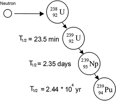
The recovery of the plutonium began with removal of the aluminum cans covering the fuel slugs (either mechanically or chemically dissolving). The fuel elements containing uranium, plutonium, and fission products were dissolved in nitric acid. The plutonium in solution was reduced to the +4 state and precipitated with BiPO4. The uranium was held in solution using sulfate ion, ![]() to form a soluble uranium ion. This separation step split the very small amount of plutonium from the uranium and most of the fission products. Some of the fission products stayed with the plutonium. Dissolving the plutonium-BiPO4 precipitate and oxidizing the plutonium to the +6 state soluble in acid solution yields nearly pure plutonium. The impurities remained insoluble and were separated with the precipitate. The plutonium in solution was again reduced to the +4 state and the precipitation cycle repeated two times with the extracted plutonium ending in a final acid solution. The third BiPO4 precipitation cycle was followed by a cycle using LaF3 to remove the last traces of fission products [34].
to form a soluble uranium ion. This separation step split the very small amount of plutonium from the uranium and most of the fission products. Some of the fission products stayed with the plutonium. Dissolving the plutonium-BiPO4 precipitate and oxidizing the plutonium to the +6 state soluble in acid solution yields nearly pure plutonium. The impurities remained insoluble and were separated with the precipitate. The plutonium in solution was again reduced to the +4 state and the precipitation cycle repeated two times with the extracted plutonium ending in a final acid solution. The third BiPO4 precipitation cycle was followed by a cycle using LaF3 to remove the last traces of fission products [34].
It is remarkable that following all of these steps, the recovery of plutonium was greater than 95% and the decontamination factor of the plutonium product exceeded 107. This might have been considered good luck, since the decision to use the BiPO4 precipitation process was made well before the chemistry of plutonium was known—“hats off” to the insight of the scientists working on the project.
The “fast track” military schedule ignored some of the disadvantages of the process. A batch process always requires careful operator attention. The quantity of process chemicals produced a large volume of high-level radioactive liquid waste that still remains stored in huge tanks on the Hanford site and represents a World War II legacy waste treatment problem. Nearly all of the uranium remained in the waste stream and additional processing steps are required to separate the uranium from the fission products.
There is an additional difficulty working with irradiated uranium. All of the reactor operations and the chemical treatment must be done behind radiation shielding to protect the plant personnel from the high-energy gamma radiation produced by the decay of the fission products. Mechanical manipulators were designed to provide remote services to operate and maintain the equipment handling irradiate fuel. A 1945 audit indicated the Hanford plutonium production facility cost over $300 million (1945 dollars) [35]. When we include the uranium enrichment plant at Oak Ridge, TN, the weapons development site at Los Alamos. NM, the metallurgical laboratory in Chicago, the Manhattan Project represents the most ambitious, expensive, successful research and development project in history.
PUREX Process—Cold War Plutonium Production
The signing of the German and Japanese surrender documents was completed in August 1945 and the end of World War II brought a national “sigh of relief.” Military personnel quickly returned to private life. This was also true for many of the science and technology people working on the Manhattan project. The advantage of possessing the most powerful weapon was obvious, but the authority over the program was transferred from the Army (military) to a new civilian committee, the Atomic Energy Commission. Production of plutonium was continued under Atomic Energy Commission (AEC) control.
The first nuclear explosion in the Soviet Union in 1949 came as no big surprise. Winston Churchill’s “Iron Curtain” speech in March 1946 certainly gave warning of the aggressive attitude of the Stalin led Soviet Union toward its World War II allies. This represents the introduction into the decades long Cold War.
The Cold War assured the military would demand additional plutonium production. Countercurrent extraction was a mature technology when the batch process was selected for recovery and purification of plutonium. The operation of a continuous extraction train is more complicated than a batch process and there was little time available for process development. The bismuth phosphate batch process continued in service until 1951.
The source of plutonium would remain natural uranium irradiated in the graphite-moderated reactors at Hanford Washington and newer reactors built at Savannah River, South Carolina. The irradiation times remained short with about 1/4000 for the U-238 atoms converted to plutonium. There were three essential requirements of any proposed separation process:
1. All of the plutonium must be recovered as weapons grade material.
2. The uranium must be recovered essentially free of radioactive fission products.
3. The mass of the fission product waste stream should be greatly reduced (as small as practical.)
The radioactive fission product content of the uranium and the plutonium was set at about the level of natural uranium so these metals could be handled and machined without the cumbersome gamma radiation shielding.
It was known in 1945 that tri-n-butyl phosphate (TBP) could be used as an extraction agent for nuclear fuels [36]. The PUREX (Plutonium-URanium-EXtraction) process was designed to remove the fission products, the source of the essentially all of the gamma radiation in the product uranium and plutonium, requiring separation factors of 106–107. The toxicity of plutonium, inhaled or ingested, required plutonium separation from uranium to be set at 108. A little uranium in the plutonium was not considered a problem. The recovery of both the uranium for recycle and the plutonium product was to be 99+%. These separation process specifications far exceeded the highest standards in industrial practice at the time.
Since the PUREX process was designed to replace the bismuth phosphate batch process, the feed irradiated uranium fuel was the same. The first step was to chemically remove the aluminum cans on the uranium fuel slugs and then dissolve the fuel in hot nitric acid. The pH and metal concentration of this feed solution was adjusted to maximize the solubility of the plutonium and uranium in the organic extract phase. This feed solution entered the center of the first extraction train.
The first extraction separated the plutonium and uranium from the fission products. The organic extraction solvent was a nominal 30 (vol.)% TBP in a paraffinic hydrocarbon (much like kerosene) that gives good flow characteristics in the liquid extraction contact stages. The organic solvent enters one end of the extraction train with the first contact stage removing all but a trace of the uranium and plutonium from the acid (aqueous) phase containing the fission products. The TBP solution continues to load with U and Pu at each stage until it reaches the feed stage. Then 2–3 molar nitric acid is fed at the other end of the extraction train and scrubs fission product metals from the TBP phase. The contact time between the TBP and acid phase containing the fission products was kept short to minimize the gamma radiation damage to the organic phase. The acid solution goes to a nitric acid recovery unit that recovers the nitric acid values, removes water and concentrates the fission product solution for storage.
A second extraction train receives the TBP solvent stream with one end fed dilute nitric acid containing chemicals that reduce the plutonium to the acid soluble Pu+3 state. Fresh TBP is fed to the other end of the train to remove traces of uranium stripped into the acid stream that now contains the plutonium. This extraction step completes the separation of the large fraction that is uranium from the small plutonium fraction.
The uranium is released from the TBP with a scrubbing train using dilute acid. The stripped TBP goes to solvent recovery and is cleaned up for recycle. Water is evaporated from the dilute acid containing the uranium. The pH is adjusted, and the uranium extracted with countercurrent TBP-acid scrub to remove traces of plutonium and fission products. The spent nitric acid goes to nitric acid recovery and the fission product waste, including a trace of plutonium that goes to waste concentration.
The uranium is recovered from the TBP with very dilute nitric acid scrub. The TBP is recycled and the uranium solution evaporated. There may be a final uranium “polishing step” before the steps to produce the final uranium product, a uranium nitrate solution or de-nitration to form UO3.
The plutonium that was left in the acid solution is oxidized to the Pu+4 state and center fed to an extractor which collects the plutonium in the TBP phase and leaves impurities in the acid phase. The TBP phase goes to a dilute acid stripper to recover the product as plutonium nitrate solution. There usually is a product plutonium-polishing step to attain the maximum purity of the product. The stripped organic TBP phase and the aqueous acid phase are recycled to recover nitric acid values, renew the organic phase, and reduce the volume of the waste stream.
There are several variations of the general separation steps described above. The first PUREX process plant to produce weapons grade plutonium was located at the AEC Savannah River Plant and began production in November 1954 [37]. With this successful demonstration, another plant began operation at the Hanford site in January 1956. Improvements in the operation of the PUREX process continued with operating experience.
The demands for high purity plutonium and uranium made the development of the PUREX process a real separation technology challenge. Add to this the demands for personnel safety, protection from the toxicity of the heavy metals, and the continuous gamma radiation from the fission products. The engineering task included developing mechanical manipulaters to perform all of the process operations and equipment maintenance tasks protected by the radiation shielding. This technology was developed for the military and is the basis for modified PUREX to reprocess domestic spent nuclear fuel.
PUREX Process—Domestic Spent Fuel
The first nuclear reactors designed to produce electricity were installed in nuclear submarines. Such a reactor must provide the electric and thermal power required to sustain the crew under water, long term, and then to provide the additional variable power required during battle maneuvers. The total mass and the size of the reactor must fit on the submarine and protect the crew from fission product gamma radiation. These reactor designs, the nuclear fuel composition and configuration were classified “Top Secret” by the military. Civilian contractors built these reactors and their engineers saw an opportunity, and were encouraged, to extend this technology to civilian electric power production under the Atoms for Peace Initiative.
The nuclear reactors for domestic electric power production were designed to provide base line power, continuous operation at power plant design capacity for long periods between refueling and mechanical equipment maintenance shutdowns. The two designs widely adopted and deployed in the United States were the BWR and the PWR reactors. The fuel for these reactors is uranium oxide slightly enriched to between 2.6–4% U-235.
Uranium oxide fuel is commercially manufactured into small, cylindrical pellets about 12–13 millimeters in diameter and the same length. These pellets are loaded into metal tubes (about 1 centimeter OD), originally stainless steel but soon replaced by Zircaloy (mostly pure zirconium alloyed with tin, nickel, chromium, and iron). The end cap on each end of the tube is welded to isolate the uranium fuel and all the fission products (gases and solids) from the water in the reactor. Often, these tubes are pressurized with helium to improve the heat transfer from the fuel pellets to the tube wall. Zircaloy has a low neutron capture cross section, is corrosion resistant, and quickly becomes the material of choice for this application [38].
The fuel tubes for a typical PWR are fixed in a fuel assembly consisting of a 15×15 array of fuel tubes fixed in place with space to circulate pressurized water to remove heat and to serve as the neutron moderator (to slow down the neutrons). Such a fuel assembly is about 4 meters long and weighs about 658 kg. It contains about 523 kg of uranium oxide (461 kg of uranium metal). There is 135 kg of Zircaloy and hardware metal in each fuel assembly [39]. These fuel assemblies contain the spent nuclear fuel that is the feed for spent fuel reprocessing.
The composition of the spent fuel is determined by the initial composition of the fuel and the radiation history of the fuel assembly. There are three sources of radioisotopes formed during the power cycle of the fuel:
• Fission products formed by the splitting of the fissile elements, the initial U-235 and the Pu-239 that is formed by neutron capture of the U-238 in the fuel during the fuel cycle)
• The transuranic elements formed by neutron capture (neptunium, plutonium, americium, and curium)
• The activation products formed by exposure of atoms to the high radiation field in the reactor.
Immediately following reactor shutdown, the fuel will contain more than 350 nuclides, many with very short half-lives that decay in seconds or minutes [40]. These radioactive decay processes produce thermal energy (heat) and gamma radiation that must be managed when the spent fuel elements are stored.
For example, consider a reactor that operates with a fuel burn up to 30,000 megawatt days per ton (1000 kg) of uranium metal in the fuel. Immediately after shutdown, these fuel elements will produce nearly 2000 kW of thermal energy and a nuclide radioactivity of about 2×10⁸ curies per ton. The fuel assemblies are stored in a deep pool of water (containing soluble boron, a neutron absorber) located at each power plant where the thermal energy is removed and the water serves as radiation shielding [41]. The thermal energy release and the gamma radiation decrease with time as each radioactive isotope decays and after 10 years the thermal energy release is about 1.1 kW and the radioactivity is about 3.9×10⁵ curies per tonne. The thermal energy release is still much too high to allow isolated underground storage. The gamma radiation requires bulky biological shielding to protect persons transporting spent fuel to any remote storage or reprocessing site.
Reprocessing: Recovery of Unused Fuel
In the beginning of the twenty-first century, reprocessing technology in the United Sates has not been sufficiently developed for commercial spent nuclear fuel to be economically competitive with new uranium. An agreement signed during President Carter’s administration closed out the option of reprocessing domestic spent fuel. Reprocessing would make plutonium more easily attainable to terrorists—if kept in the spent fuel and with the highly radioactive fission products it is not as available.
The fear of nuclear weapons proliferation is a major obstacle to domestic nuclear fuel reprocessing. Security assurances of excess military plutonium and highly enriched uranium will be important in any decision to proceed to commercial spent fuel reprocessing.
The plutonium in the spent nuclear fuel is not suitable for bombs, even if concentrated, since it contains too much of the Pu-240 isotope [42]. The separation of the Pu-240 from the Pu-239 would be more difficult than concentrating bomb-grade U-235 from fresh uranium ore because the atomic weights of Pu-239 and Pu-240 are even more nearly the same than U-235 and U-238 [43]. It is the mass difference between the isotopes that allow the mechanical centrifuge separations. Uranium isotope separation is expensive—plutonium isotope separation would be more expensive.
Since nuclear waste handling is a known significant expense of nuclear power generation, most governments levy a tax on nuclear electrical power to be applied toward disposal. In the United States, this tax is 0.1 cents per kilowatt-hour. This fund has more than $36 billion available (without interest computed) [44]. If existing nuclear plants reprocessed spent fuel rods, they could store the concentrated waste indefinitely. If the revenues collected for handling nuclear waste were used to reprocess nuclear waste, the waste problem would be solved and reprocessing would be viable. One means to supplement fissile fuel content in reprocessed fuel is to use the plutonium in excess nuclear weapon’s inventories.
The British and French have over 35 years of experience in reprocessing spent nuclear fuel. The PUREX process is the primary technology in use.
PUREX Process
Figure 8.33 summarizes the PUREX process steps for recovering spent nuclear fuel. The first step for commercial nuclear fuel reprocessing is opening the fuel tubes so the irradiated fuel can be dissolved in nitric acid. Chemical de-cladding used in military plutonium production is replaced by mechanical shearing the commercial reactor fuel assemblies into short lengths. This releases helium (if helium was filled during fuel manufacture) and the fission product gases (isotopes of krypton, xenon, tritium are examples) that must be collected. After a reasonable time these gases convert to stable isotopes and can be released. Radioisotopes, including Kr-84, I-131, and Xe-133, are currently vented to the atmosphere [45]. Other treatment may also be necessary. The long-lived radioactive iodine released during this step is given special attention [46].

The next step is to dissolve the fuel metal oxides containing fission products, uranium, plutonium, and transuranic metals in nitric acid. The stainless steel and Zircaloy pieces from the fuel assemblies do not dissolve and are separated from the nitric acid solution, washed to remove all of the uranium, fission products, and transuranic elements, dried and packaged as low-level radioactive waste. The nitric acid solution pH is adjusted to assure that uranium and plutonium are in the most favorable oxidation states for extraction.
Some of the fission products are (or form) metal compounds that exceed solubility limits and these are filtered out before entering the extraction train. For each metric ton of metal in the spent fuel, there will be about 944–946 kg of U-238, 8–11 kg of U-235, 5–9 kg of Pu-239, and 1–9 kg of heavy metal isotopes with atomic numbers greater than uranium (transuranic) in the periodic table. The total mass of the fission product metals (more than 40 elements) is about 34 kg [47].
A small fraction of the fuel does not dissolve in nitric acid. These residues vary depending on the fuel characteristics, the time the fuel is irradiated, and the procedure used to dissolve the fuel [48]. The acid solution must be clarified before it is fed to the extraction train. These residue solids will be radioactive and a heat source that requires special handling, especially for “young spent fuel” (spent fuel aged less than 10 years).
The first extraction train removes the uranium and plutonium to the organic TBP phase and leaves the 43 g of minor actinides and fission product metals in the aqueous phase. The strong gamma radiation of the fission products that cause radiological damage to the TBP phase is essentially all removed in this first extraction step. Extraction steps to strip the remaining fission products and to separate the uranium and plutonium follow, with minor modification of the process for the production of plutonium.
This extraction process can be operated to extract only uranium (UREX) (see Figure 8.34) or plutonium and uranium (PUREX). A very pure uranium is required to feed the U-235 enrichment process for new uranium oxide fuel—the fuel for which light water reactors were designed. UREX uranium contains 0.7–1.1% U-235, about the same as natural uranium.

There are other uranium isotopes in this recycle stream that “tag along” and these are neutron absorbers in the recycled fuel for the LWR. These isotopes accumulate each time the fuel is recycled and the different decay routes produce thermal energy and high-energy gamma radiation which may require protective clothing or remote handling of recycled uranium metal [50].
The PUREX process does produce pure plutonium, the source of strong objection from the members of the nuclear weapons nonproliferation people. The proposal to mix plutonium oxide with uranium oxide to form a mixed oxide fuel (MOX) that can be used as fuel for light water reactors has been used in commercial reactors in Europe. MOX fuels have been successfully used on a limited basis and this fuel mixture does not present a weapons threat.
Plutonium represents the key ingredient for closing the uranium fuel cycle and it is an important source of energy for future nuclear power plants. The current fleet of LWRs in the United States produce about 2000 tons of spent fuel per year containing about 0.5–0.9 % Pu, yielding 10–20 tons of plutonium. The age of the spent fuel (how long it has been in storage) changes the ratio of the isotopes of plutonium and the performance of the plutonium fuel in the LWR reactor. The energy producing fissile materials in the light water moderated reactor are U-235 and Pu-239. The other isotopes accumulate with each reprocessing cycle. This disincentive for reprocessing can be overcome using the reprocessed fuel in a new generation of fast flux (fast neutron) reactors discussed below.
Further processing can be performed on the mixture of uranium and plutonium leaving the PUREX process to prepare pure uranium and pure plutonium. The PUREX process produces gaseous effluents and cladding hulls that are not hazardous. The fission products are concentrated into a solid high-level waste. Since the nitric acid is recycled the solvents (primarily tributylphosphate, TBP) is also recycled. In general, the acid and solvents do not add to the volume of waste resulting is a substantial decrease in the total volume of radioactive waste from these new processes.
The PUREX process separates the uranium and plutonium from the spent fuel, but the fission products and minor actinides that remain in the waste stream represent a very long-term waste storage problem. An advanced form of PUREX known as URanium EXtraction (UREX) has environmental and antiproliferation advantages over PUREX as described by the following excerpt from the DOE 2003 Report to Congress [51].
In the UREX process, plutonium, and other transuranics, and fission products are extracted in a single stream from which transuranics could be extracted for reuse in nuclear fuel. The feature of UREX that makes it much more proliferation resistant than PUREX is the continual presence of minor actinides, the high radioactivity and thermal characteristics of which make these materials relatively unattractive to potential proliferaters.
Additionally, because UREX does not place these actinides in the waste stream, there could be a significant reduction in the amount of highlevel waste produced. Short-lived radioactive isotopes are separated and may be stored and allowed to decay to harmless elements over several decades.
Further, experiments completed in 2002 have proven UREX to be capable of removing uranium from waste at such a high level of purity that we expect it to be sufficiently free of high-level radioactive contaminants to allow it to be disposed of as low-level waste or reused as reactor fuel. These laboratory-scale UREX tests have proven uranium separation at purity levels of 99.999 percent. If spent fuel were processed in this manner, the potential exists to reduce significantly the volume of high-level waste. An additional advantage of UREX is the use of acetohydroxamic acid, which enables the use of chemical processes that are far more environmentally friendly than PUREX.
AFCI (Advanced Fuel Cycle Initiative) Series One research would include the continued development of aqueous chemical treatment technologies including the possible demonstration of UREX at a scale relevant to its eventual commercial use.
An advanced development of UREX, referred to as “UREX+,” would be a key element of an AFCI program. This additional research would evaluate different aqueous chemical treatment methods to separate selected actinide and fission product isotopes from the UREX stream after the uranium has been extracted in a manner that minimizes waste. For example, UREX+ would provide mixtures of plutonium and selected minor actinides for preparing proliferation-resistant fuels.
Long-lived fission products, iodine-129 and technitium-99, which are major contributors to the long-term radiotoxicity from spent fuel, could be separated for incorporation into targets for destruction in reactors. This work would allow the program to obtain a detailed understanding of all waste streams, the data needed for understanding what would be needed in a commercial scale treatment facility, and provide the basis for estimating the cost to design, build, and operate such a facility.
If implemented successfully, this treatment technology could significantly reduce the volume of high-level waste from commercial nuclear power. This accomplishment would reduce the cost of the first repository and potentially eliminate the technical requirement for a second.
Key programmatic treatment technology elements for AFCI Series One would include: (i) laboratory demonstration of UREX+ using radioactive materials; (ii) engineering scale demonstration of UREX+; (iii) laboratory demonstration of PYROX (pyro-chemical dry treatment) technology using spent LWR fuel; (iv) demonstration of PYROX actinide recovery; (v) engineering scale demonstration of PYROX using radioactive materials; (vi) demonstration of large-scale metal waste form technology; and (vii) treatment facility requirements, costs, and design studies.
The UREX treatment technology, combined with additional processing steps, provides a way to produce proliferation-resistant transmutation fuels for use in LWRs or gas-cooled reactors.
Successful implementation of this technology would require dealing with several issues such as fabrication and testing of trans-plutonic-bearing fuels, which would require remote fabrication.
To support this effort, research on transmutation fuels would focus on the development of proliferation-resistant fuel forms, preliminary fuel irradiation testing, and analysis of the resulting transmutation system (including waste streams). In the case of LWR transmutation fuels, several technology options would be considered, including the French CORAIL, Advanced Plutonium Assembly systems, advanced assembly designs, and inert matrix/non-fertile fuel concepts.
Gas-cooled reactors use very small spherical fuel particles, which if manufactured with advanced coating technology, are strong enough to permit much higher burnup than are possible with LWRs, and are difficult to reprocess. Very high destruction levels of plutonium (over 90%) have already been demonstrated using pure plutonium fuels; however, the challenge remains to achieve these impressive burnups with proliferation-resistant fuels. Research is needed to address this challenge and will include the development of proliferation-resistant fuel forms, fuel irradiation testing at the High Flux Isotope Reactor at Oak Ridge National Laboratory or the ATR at the Idaho National Engineering and Environmental Laboratory (INEEL), and analysis of the resulting transmutation system performance for gas cooled reactor fuel.
Advanced Aqueous Separation
More recently, Argonne National Laboratory personnel have developed an advanced aqueous process called UREX+ has been demonstrated on a laboratory scale [52]. The UREX+ process consists of five solvent extraction steps that separate the dissolved spent nuclear fuel (the PUREX feed) into seven fractions. In the first stage, the uranium and technetium are recovered in separate streams with high total recovery and purity. Next, the cesium and strontium (heat producers, a problem in repository waste storage) are removed. A little feed adjustment allows the plutonium and neptunium to be recovered with impurity levels that allow these actinides to be incorporated into MOX fuel. The fourth step recovers the minor actinides and the rare earth elements. The final step separates the minor actinides from the rare earth elements.
The many metal species in spent fuel dissolved in nitric acid form a complex chemical mixture. The UREX+ process demonstration indicated that with additional work to understand this chemistry and to refine the separation parameters, the product streams can yield recycle nuclear fuel, radioactive isotopes that can be formed into targets for transmutation, and a waste product that can meet the demands for long-term geological storage. This work demonstrates an option for the treatment of the inventory of spent fuel accumulating from the current fleet of light water reactors.
Tables 8.13 and 8.14 provide a summary comparison of these aqueous treatment processes.
Table 8.13
Summary of separations in PUREX and UREX processes


Experimental Breeder Reactor II
The nuclear reactors designed to produce military plutonium used uranium metal as fuel. As early as the mid-1940s there were attempts to demonstrate the use of plutonium as a fuel for power production [53]. In 1963, Experimental Breeder Reactor II (EBR-II) was the first fast flux (the high-energy neutron spectrum produced at fission) reactor. The fuel core, the circulation pumps, and the primary heat exchanger were submerged in a pool of liquid sodium contained in the reactor vessel.
Sodium has a small neutron cross section that minimizes the neutron slowing down effect. The primary sodium coolant that is exposed to high-energy radiation in the reactor core becomes radioactive (a portion of the sodium becomes Na24 with a 15 hr half-life). The secondary liquid sodium loop is circulated through the heat exchanger and transports the thermal energy to a steam generator to supply steam to a turbine. This higher pressure secondary sodium would leak into the reactor pool if there were a leak in the sodium heat exchanger. This would prevent radioactive sodium release from the reactor vessel.
The EBR-II operated until 1994, over 30 years without heat exchange problems. The facility was designed to “breed” plutonium to extend the inventory of fissile uranium. Later, the fuel loading was modified to demonstrate it could be a “plutonium burner” (to reduce the inventory of surplus military plutonium). EBR-II provided the test bed for irradiation studies of many proposed metallic and oxide fuels for military and commercial applications [54].
The EBR-II was designed to be an integral nuclear power plant. This included on site nuclear fuel reprocessing and new fuel production on the reactor site. The fertile atoms (U-238) in the fuel absorb neutrons to form fissile atoms (Pu-239). These would join the fissile metals in the initial fuel to serve as fuel in the fast neutron flux. The demonstration included the production of steam to drive a turbine to produce electric power to complete the simulation of a commercial power plant.
The engineers on the EBR-II program steadily increased the performance of the fuel for the reactor. Initial problems with the fuel showed the uranium metal expanded during irradiation, mechanically stressing the tubes containing the fuel limiting service to about 1% of the U-235 in the fuel. The swelling problem was solved using a uranium–plutonium–zirconium alloy fuel that achieved 10% fission of the fuel (compared to 3.4% for commercial LWR metal oxide fueled reactors). The metal fuel was sealed in stainless steel tubes with sodium metal filling the space between the fuel and the tube wall (sodium bonded fuel). The all-metal fuel elements in contact with the liquid sodium pool provided high-heat transfer rates, smaller in core temperature gradients making possible a smaller reactor core.
The original EBR-II fuel was enriched uranium to serve as a driver (neutron source) for the production of plutonium. The demonstration of “breeding” plutonium in uranium 238 rods surrounding the reactor core required the recovery and recycling of the new plutonium as fuel. Collaboration between Argonne National Laboratory in Illinois and the Idaho National Laboratory developed a “dry” (no water, no nitric acid) process they called pyropartitioning [55].
Pyrometallurgical Reprocessing
Unlike the PUREX and UREX processes, pyrometallurgical processing is based on electrochemical separation. Spent fuel metal is dissolved in the salts of the electrorefiner. Oxide fuels must first be reduced to metal prior to electrolysis as illustrated in Figure 8.35. Electrochemical separation can be compact and relatively simple; however, the basic process mixes the cladding with fission products, forming more high-level waste than some alternatives.

In the pyropartitioning process, the spent fuel elements are chopped into short pieces and placed in metal basket in a pool of molten salt. A minimum melting (eutectic) mixture of potassium chloride and lithium chloride (KCl–LiCl) was used as the solvent. An electric current passed from the chopped fuel basket serving as an anode where all the heavy metals and fission products in the spent fuel oxidize to form metal chlorides dissolved in the molten salt. An inert metal cathode serves to collect the selectively reduced heavy metals from the salt. Uranium is the first metal collected and since it is the most abundant metal in the spent fuel the deposition voltage separating them as they selectively deposit on the cathode based on the electronegative potential for each metal chloride in the salt (the voltage for deposition of each metal is like the voltage of the lead-acid battery used in an automobile). This electrolytic process separates the uranium and plutonium from the fission products and the minor actinides producing uranium–plutonium metal. The metal deposited on the cathode is harvested, separated from adhering salt, and cast into new metallic fuel pins for fuel or sent to storage.
The removal of the uranium and plutonium (about 94–95% of the mass) leaves the fission products and the transuranic elements in the salt. The metallic sodium bonding agent in the fuel elements forms sodium chloride. The melting temperature of the KCl–LiCl eutectic salt increases as metal chlorides build up. The saturated solvent salt is removed, most of the KCl–LiCl recovered, and the remainder formed into ceramic waste form suitable for long-term storage.
There are noble metal fission products that remain solid during the electrodeposition and these are combined with the fuel cladding pieces that remain in the anode basket. These solids are stabilized into a metallic waste form and sent to storage.
All of the processing steps must be done in an inert atmosphere (argon) that is essentially free of water, hydrogen, nitrogen, and oxygen. The actinide and rare earth metals in the spent fuel are chemically active and readily form oxides, nitrides, and hydrides that are insoluble in the molten salt. They collect as insoluble solids in the processing equipment. The radioactive fission products in the spent fuel produce high-energy gamma radiation making radiation shielding necessary.
Remote handling is required for all of the steps in the fuel reprocessing and new fuel fabrication for the EBR-II fuel. Protection from the health hazards of inhaling or ingesting the radioactive heavy metals are minimal because there is total isolation for the fuel processing that serves to protect the workers.
The EBR-II experimental program achievements include: Generation of over 2 billion kilowatt-hours of electricity; irradiation of over 30,000 specimens of fuel, structural, and neutron absorber materials; advance instrumentation testing; a test of inherent reactor safety with demonstration of total loss of coolant flow; and advanced computer technology applied to diagnostics and control [56]. In December 1995, James Toscas (Executive Director of the American Nuclear Society) stated, “EBR-II is arguably the most successful test reactor ever.” The technology informing the next generation of fast flux reactors depends on data collected during the EBR-II experimental run.
The pyropartitioning process can be used to separate the nuclear fuel components from fission products to make fuel for the next generation of fast flux reactors. The LWR spent fuel in the United States is estimated to reach 70,000 metric tons in 2015. The current fleet of reactors in the United States produce about 2000 metric tons of spent fuel per year. Anticipating commercial scale processes will be required to recover fuel values and reduce the mass of radioactive waste going to a repository, the Chemical Engineering Division at Argonne National Laboratories has completed a demonstration of an electrochemical process that reduces the oxide fuel to metal [57]. The reduced metal would be fed to the pyropartitioning process to recover the fuel values from the fission products.
The promise and future of nuclear power systems depends on the success of research and development programs. There must be investments to develop and deploy new energy systems for nuclear energy to play its role in the future of electric power generation.
Mining and Processing
Uranium ore is mined and processed to uranium oxide concentrate (U3O8) that is sold as a feedstock for further processing into reactor fuel. For use as reactor fuel, the uranium must be enriched in the U-235 isotope. This is performed in a gas-phase process by forming uranium hexafluoride (UF6). Enrichment is used to increase the 0.7% natural U-235 concentration to 2.6–5%. The enriched uranium is processed to uranium dioxide (UO2) and formed into fuel pellets that are placed in tubes as reactor fuel rods.
Today’s world nuclear power production includes about 437 nuclear reactors with a capacity of 381,000 megawatts. Every year each 1000 megawatts of power production converts 750 kg of U-235 (and some U-238/Pu-239) into 750 kg of waste fission material mixed with about 30,000 kg of unused fissionable elements (U-235, U-238, and Pu-239).
Proven world uranium reserves are 3.3 million tons [58] with vast deposits in Australia and Canada [59]. Estimated reserves in addition to the proven reserves include another 10.7 million tons. Recently discovered uranium deposits in Canada are so rich in uranium that they must be mined with robots to avoid exposing miners to their natural radiation. In the United States, 56,000 tons of spent fuel plus 224,000 tons in depleted uranium represent 400 years of fuel for essentially all energy needs (electricity, transportation, and heating). The world estimated reserves are more than 50 times this 400-year supply—at least 20,000 years. Thorium can also be used to fuel nuclear reactors. Of course, these projections are rather superfluous since man can hardly predict how technology will create new ways to meet energy needs 30 years in advance; let along 500 or 5000 years in advance.
In the 2005 AFCI Report to Congress [60] an attempt was made to estimate unconventional uranium reserves. These reserves include 180 (sandstone), 4300 (seawater), and 800,000 (phosphate) million metric tons. If 16 million metric tons correspond to 20,000 years of uranium, 804,500 million metric tons correspond to 1 billion years of energy from uranium.
The Report to Congress classifies these massive phosphate reserves as “unconventional,” which is an ambiguous term. If not commercially viable, these reserves are at least on the edge of commercial viability.
Uranium from phos-acid is extremely (technically) viable and phosphates represent a major source of U3O8. Plants were operated in the 50’s in Florida but with the discovery of uranium in the western U.S. the facilities were shut down due to unfavorable economics [61].
In the early 1970s, interest was revived with the growth of the nuclear power industry and a significant development to improve earlier processes. Much of this work was done at Oak Ridge National Laboratory. Private companies also developed processes: United Nuclear, Freeport Chemical and Westinghouse.
International Minerals and Chemical (IMC) initially worked with United Nuclear to develop a process to recover the uranium. Their process (after installation by WR Grace) had some problems so they began their own development and eventually worked with Oak Ridge National Laboratory.
Several commercial installations resulted from these developments. Freeport installed a facility at their plant in LA. IMC installed three facilities to extract uranium. Their approach was to install primary extraction facilities at the individual phos-acid plants, then produce a concentrated uranium solution (in phos-acid). This material was then trucked to their main refinery for U3O8 recovery.
A plant was also installed at the Gardinier facility in Tampa. There were also commercial facilities in Europe. In the late 1970s, there was an excess of 3 million pounds/year of U3O8 recovered from phosphoric acid capacity in operation. (As a side note, IMC had about 2.2 MM lbs/yr of capacity and was at that time the fourth largest U3O8 producer in the United States.)
Unfortunately, Three Mile Island occurred and nuclear plant activity came to a virtual halt. The long-term U3O8 outlook diminished and existing supply contracts were not renewed as the price of U3O8 plummeted. The result was that by the early mid-1990s, all of the phos-acid based production ended due to low prices for the product.
Based on the earlier economics (adjusted for inflation), U3O8 pricing in the $35+ range in the mid-1970s, $25/lb was the price where interest was generated. Uranium from phos-acid was a commercial industry from the mid-1970s to early 1990s, and the technology is well established to restart this industry.
What is important is that nuclear fuel can be used to produce all the power needs, and the lessons of US commercial utilization demonstrate that it is safer and has a lower environmental impact than alternatives. Furthermore, since about 40 years of spent fuel have already been stockpiled, nuclear fission can provide abundant energy without additional mining and actually using more waste than it generates.
Waste Generation from Reprocessing
In the rush to develop the nuclear bomb and the subsequent arms race, vast amounts of nuclear waste were generated. The volume of the high-level waste was compounded by landfilling and containerizing chemicals dilute in the actual radioactive materials—concentrated wastes would be much less voluminous. The liquids can leach through soils and contaminate the waters around storage areas. It is this history that leads many to believe that reprocessing will generate more waste than treated. These perceptions are inaccurate.
Table 8.15 summarizes the five reprocessing options put forward by the 2004 US DOE Office of Nuclear Energy, Science and Technology AFCI Comparison Report [62]. These methods are based primarily on the recovery of uranium, plutonium, and other actinides (in some cases). These technologies reduce the volume of high-level waste by 76–88%.
Table 8.15
Estimated quantities in metric tons of chemicals, glass, and salt used in reprocessing waste by different methods
| Process | Net chemical consumption | Net glass/salt frit consumption | High-level waste | Reduction in waste |
| Once-through | 2000 | 0% | ||
| PUREX | 4.2 | 420 | 490 | 76% |
| UREX+ | 7 | 124 | 232 | 88% |
| UREX/PYRO | 5.6 | 322 | 280 | 86% |
| PYROX | 80 | 500 | 490 | 76% |
| Advanced aqueous process | 0.8 | 124 | 232 | 88% |

Assume 3.4% of spent fuel is fission products and ends up in waste and that all the glass, salts, and chemicals end up in waste.
Data from the US DOE Office of Nuclear Energy, Science and Technology Advanced Fuel Cycle Initiative (AFCI) Comparison Report.205
Table 8.16 summarizes the fuel and nonhazardous product from the reprocessing options. The components marked for recycle for future reactors includes minor actinide transuranics. The cladding would be washed to low- or zero-level waste. The secondary waste is broken contaminated equipment and materials contaminated in fuel transport. The cladding could be recycled as cladding on recycled fuel.
Table 8.16
Fuel and low-level wastes from reprocessing options
| Fissile and fertile materials | Low-level waste | ||||
| Process | Uranium | Recycled Pu, Np, Am, Cm | Recycle for future reactors | Cladding | Secondary waste |
| PUREX | 1892 | 17.0 | 0.0 | 660 | 2.1 |
| UREX+ | 1892 | 18.0 | 3.2 | 660 | 3.5 |
| UREX/PYRO | 1892 | 21.2 | 21.2 | 660 | 4.2 |
| PYROX | 1892 | 21.2 | 21.2 | 660 | 2.1 |
| Advanced aqueous process | 1892 | 18.0 | 3.2 | 660 | 1.4 |

Data from the US DOE Office of Nuclear Energy, Science and Technology Advanced Fuel Cycle Initiative (AFCI) Comparison Report.
The fate of the uranium product stream from reprocessing is not obvious. The problem is that the amount of U-235 (about 1%) in the uranium is about the same as natural uranium, and this means it has little or no fuel value. The motivation for use of the uranium reprocessing stream is to avoid it becoming a low-level radioactive waste.
Waste Minimization
The reprocessing technologies in Table 8.16 are based on recovering uranium and plutonium. This is only one of the following three phases of spent fuel reprocessing:
Phase 2—minimize waste by separating stable fission products from high level fission products
Phase 3—transmute the high level fission products into non-hazardous materials.
Phases 2 and 3 bring additional costs and require technology developments. Instead of depositing the glass-stabilized wastes, the fission products could be placed in temporary storage (30–60 years) with the objective of processing in the future when larger volumes of these materials have accumulated. These wastes could be stored at the reprocessing facility, and the temporary storage could reduce the consumption of glass.
Waste minimization provides as opportunity to reduce 3.4 parts of high-level fission product waste to 0.4 part of high-level waste. Due to the different properties of the elements (nuclides) in fission waste, a variety of chemical processes would provide the desired waste minimization. The stable isotopes would not be high-level waste. In this processing, the 0.4 part of unstable products could again be placed in temporary storage.
The volume of the unstable products would be low. Technology is available to transmute many of the unstable isotopes—using fast-spectrum reactors and/or accelerators. Storage for centuries would be unnecessary. The waste would be managed with a policy of continuous reduction of the waste that requires long-term storage.
Report to Congress
In January 2003, the US DOE prepared the Report to Congress on the AFCI: The Future Path for Advanced Spent Fuel Treatment and Transmutation Research [63]. This official document confirms the potential of nuclear technology to meet our energy needs without continued growth of spent nuclear fuel as illustrated by the maximum in civilian spent fuel storage at about 2040 according to Figure 8.36 prepared from this DOE report.

The mass of radioactive waste would actually reduce if the stable elements were removed and used. For every 3.4 parts of fission products, 3 parts are stable after moderate storage times. The volume of remaining materials having high radioactive hazards is quite small. If the entire inventory of these materials (for 40 years) were melted into a metal cube, that cube would be less than the size of a small house. It is an option to store this concentrated material for several decades or even a century.
When the time is right (due to accumulation of volume or availability of technology), transmutation technology could be used to transform even that small fraction into benign, stable waste.
Example Calculations
Example calculations are from DOE Fundamentals Handbook: Nuclear Physics and Reactor Theory. Volume 1 of 2.
Calculation of Mass Defect—The mass defect can be calculated using Equation 8.5. In calculating the mass defect it is important to use the full accuracy of mass measurements because the difference in mass is small compared to the mass of the atom. Rounding off the masses of atoms and particles to three or four significant digits prior to the calculation will result in a calculated mass defect of zero.
(8.5)
mp=mass of a proton (1.007277 amu)
mn=mass of a neutron (1.008665 amu)
me=mass of an electron (0.000548597 amu)
Example:
Calculate the mass defect for lithium-7. The mass of lithium-7 is 7.016003 amu.
Solution:

Calculation of Binding Energy—Since the mass defect was converted to BE (binding energy) when the nucleus was formed, it is possible to calculate the BE using a conversion factor derived by the mass–energy relationship from Einstein’s Theory of Relativity. Einstein’s famous equation relating mass and energy is E=mc2 where c is the velocity of light (c=2.998×10⁸ m/sec). The energy equivalent of 1 amu can be determined by inserting this quantity of mass into Einstein’s equation and applying conversion factors.

Since 1 amu is equivalent to 931.5 MeV of energy, the BE can be calculated using Equation 8.6.
(8.6)
Example:
Calculate the mass defect and BE for U-235. One U-235 atom has a mass of 235.043924 amu.
Step 1: Calculate the mass defect using Equation 8.5.

Step 2: Use the mass defect and Equation 8.6 to calculate the BE.
