
How Can the UML Model Applications?
Your business models have established why you are building this system (i.e., how it will support the business). Your use case models have depicted how the actors will use the system. And the architecture models set the initial organization of your system. Armed with this understanding, you are well prepared to model your application. These prior models limit the “shape” of the application. The business and use case models serve to limit the design space (which is a good thing because it takes the whole universe of possible solutions and constrains that solution space). The architecture models set the overall structure of your solution. In this way, developing these models helps to control the cost and schedule of the project.
Review of Class Diagram Basics
After these boundaries are set, the most common diagram utilized to depict the static structure of your application is the class diagram. Class diagrams were introduced earlier in Chapter 4, “Architectural Modeling.” There, you saw class diagrams used for architectural modeling. In case you skipped past that section, let's review some of the class diagram basics as they pertain to application modeling and then explore some additional modeling elements you might find in these diagrams.
Classes
The class diagram shows the important classes in the application and their relationships to the other classes. Classes primarily represent the “things” in the system. Through the development of the upstream models (business, requirements, architecture), you will have already discovered many important classes. Finding these classes is much harder to do well without these other models, but it can be done. If you don't have the upstream models, just look at the problem statement for your application. Pick out the real “things” in the problem statement, such as account, aircraft, customer, product, transmitter, report, and so forth (see Figure 5-1). These will be the domain classes that should be in your class diagrams. As the models develop, non-real things will show up as classes, too, such as controller classes that coordinate processing, among others.
Figure 5-1. A class representing a planet.
But what are classes with regard to implementation of your software? Classes describe a group of similar objects. Classes are templates used to create those objects in your application.
|
Just as a cookie cutter will cut out many identical cookies, if you have a class “Planet,” you can create multiple planet objects in your application by using the Planet class. Now, having a bunch of similar planets might not be very interesting. But just as you can take many of the same cookies and vary them by adding sprinkles or icing or food coloring, you can specialize your classes through polymorphism (more on this later in this chapter).
You will need to capture important information about your classes. You do this by using attributes (similar to the descriptions in Chapter 4 around architecture, but now specific for the application's design itself). Attributes capture the essential characteristics of the class that are needed by the application—not all its characteristics, just those that are applicable to the problem at hand. For example, if your application simulates the position of the planets in the solar system, your Planet class might capture the planet's distance from the sun and orbit (see Figure 5-2) but would not capture the core composition of the planet.
Figure 5-2. Planet class with attributes.

|
|

Another way of considering attributes is in the context of data. Object-oriented analysis and design encapsulates data and processing together. Your attributes are the data that is encapsulated inside the class. The data (attributes) inside the class can be available to other classes depending on the attribute's visibility. Attributes can have public, protected, private, or package visibility (see Table 5-1).
| Visibility | Symbol | Meaning |
|---|---|---|
| Private | - | Only the class itself can access these attributes. |
| Protected | # | Any child class of this class can access these attributes. |
| Public | + | Any class can access these attributes. |
| Package | ~ | Any class in the same package can access these attributes. |
In theory, a class's attributes should all be private to ensure strong encapsulation (this protects the attributes from being accessed or altered by other objects, except as allowed by the owning object). However, you might find situations, say, during detailed design or implementation, where the level of encapsulation needs to be “softened.” In these cases, you can use the other levels of visibility to allow greater accessibility to a class's attributes. However, attributes should remain private unless there is a strong need otherwise.
So what can classes do? That is established by the class's operations.
Operations
Operations are the services that the class provides. Operations are shown in the third compartment of the class symbol. Typically, a class will contain the operations that provide access to its attributes along with the other processing functions of the class (see Figure 5-3). This is how external objects get access to the private attributes of the owning object. The class itself might not perform all of the operations within it, but the class is responsible for ensuring that something performs the operations (such as another object that is the one actually doing the work). In this case, the class is acting as a controller class, controlling all or part of the application.
Figure 5-3. Planet class with operations added.

Depending on the maturity of the diagram you have, just the operation name might be shown. As an operation develops, its full signature will develop, showing its name, parameters, default values, return type, and so forth (see Figure 5-4). How much detail is actually specified will depend on how your organization uses modeling, that is, how much detail you require before handing the design to the programmers for implementation.
Figure 5-4. Planet class with operation signature.

|
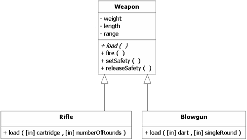
You might also encounter operations that are marked “{abstract} ”. This indicates that this class doesn't implement the operation. The operation will be implemented in a child class where you will see that same operation in the child's operation compartment. This is one way to have specific implementations of an operation. For example, the operation “load” would be implemented very differently in a “Rifle” class than in a “Blowgun” class. This is the central idea of the concept of polymorphism (see Figure 5-5): If the child specifies an operation that is also specified in the parent class, the child's operation will override the parent's operation. In this manner, the parent's behavior can be refined or replaced by the child's functionality.
Figure 5-5. Polymorphism.
A class's operations can be functions that the class executes of its own volition or functions that other objects request the class to execute. The operations that others can request of a class can be affected by visibility (refer to Table 5-1), which applies to operations as well as attributes.
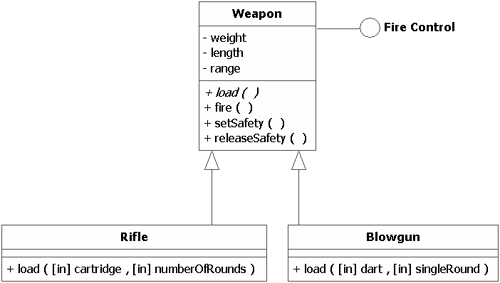
Another UML element that can restrict what services other classes can request of a class is the interface. An interface is merely a group of operations an external element can see and thus request (see Figure 5-6). The class designer determines which operations are revealed by an interface.
Figure 5-6. Class with an interface.

Associations
As discussed in Chapter 4, associations show the relationships between the objects in your system. They typically show the communication pathways between the objects, which can be bidirectional or unidirectional, as discussed earlier. Directionality (a.k.a. navigability) usually should be specified later in the design phase when you have more knowledge of how the processing will actually be traversing the associations. In this way, you will know how the implementation of the associations should be optimized.
Other Association Adornments
Some of the adornments that appear on association ends (e.g., multiplicity, diamonds) were also discussed in Chapter 4. You will often run into a few others.
Rolenames can appear on the end of an association. These rolenames describe the class that is attached to that same end of the association as the rolename. The function of the rolename is to indicate how the class will behave in that specific relationship with the class it is associated with. This is similar to the various roles we all play in life. When I am serving as an engineer, I perform certain behaviors. When I am acting as an investor, I perform different behaviors (although there can be some common behaviors). An engineer might read, analyze, design, build, etc. An investor might read, analyze, buy, sell, manage an account, etc. (see Figure 5-7). In this way, rolenames partition the behaviors of their classes.
Figure 5-7. Rolenames.

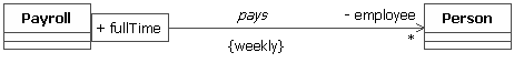
Although rolenames partition the behavior(s) a class presents in an association with another class, qualifiers partition the set of objects that can participate in an association. Let's look at some examples using the classes Payroll and Person.
Figure 5-8 says that the Payroll department pays a Person. Figure 5-9 shows how a rolename can be added for clarity—Payroll is paying a Person who is acting as an employee (not a contractor or vendor). Yet, in both of these diagrams, there is little specificity.
Figure 5-8. Unadorned association.
![]()
Figure 5-9. Association with rolename.
![]()
When we add a qualifier (employee number), as in Figure 5-10, we now know that only that specific Person object participates in the association (i.e., only that Person with a specific employee number is being paid). If you augment this with multiplicity, you add more information to the model. In Figure 5-11, we see that because of the 0..1 multiplicity, Payroll pays either nobody (indicating an employee number that is not assigned to an employee) or one specific employee.
Figure 5-10. Association with rolename and qualifier.
![]()
Figure 5-11. Association with rolename, qualifier, and multiplicity.
![]()
Change the qualifier and multiplicity, and you get new semantics, as in Figure 5-12, where Payroll pays many full-time employees (the part-time employees are excluded by the qualifier “full-time”).
Figure 5-12. Association with rolename and qualifier selecting a set of objects.
![]()
More on Class Diagrams
Aggregation and Composition
In Chapter 4, two related association types were mentioned—aggregation and composition. (In UML 2.0, a composition association is also called a composite aggregation.) Figure 5-13 shows both associations.
Figure 5-13. Aggregation and composition associations.
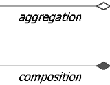
Aggregation is shown with an empty (or hollow) diamond, whereas composition is noted with a filled-in diamond. In both cases, the diamond appears on the “Whole” end of the association. These associations are read: “The Part is part of the Whole” and “The Whole has a Part” (the number of specific parts is determined by the multiplicity on the part end of the association).
These associations carry the special meaning that one element of the association “is part of” the other. The difference between aggregation and composition is how tight the relationship is between the participating elements. Aggregation is a looser form of association, whereas composition indicates a much tighter form of containment. In a composition, the Part(s) can only be part of one Whole. Also, with composition, when the Whole is destroyed, so are all its parts. (In fact, it is the responsibility of the Whole to ensure that its parts are destroyed.) In Figure 5-14, you can see such relationships as they pertain to a flashlight.
Figure 5-14. Aggregation and composition of a flashlight.

A flashlight has a switch. This is a composition because the switch is part of that one flashlight—When you throw away (destroy) the flashlight, the switch goes with it. On the other hand, you could remove the battery from the flashlight and use it in another one, which is why this association is shown as an aggregation.
One caveat—these “part of” relationships aren't just for physical elements. For example, a Person can have a Belief, or a BrandName can have MarketValue.
Generalization
You have seen the generalization relationship earlier in this chapter (refer to Figure 5-5). The class at the arrowhead end of the association is the superclass. The class or classes at the non-arrowhead end of this association are the subclasses. The superclass-subclass relationship is similar to a parent-child relationship. The children (subclasses) inherit attributes, operations, and relationships from the parent (superclass). Figure 5-15 shows such a relationship. The parent (Weapon) has the attributes weight, length, and range. Through inheritance, the children (Rifle and Blowgun) inherit these attributes; that is, they also have weight, length, and range, even though they might not be explicitly shown in these subclasses. The same holds true for the operations—the children inherit them from the parent. In this particular case, as discussed earlier, the operation “load” is overridden (i.e., redefined) by the children.
Figure 5-15. Generalization.
Association Classes
Sometimes, as you start to connect all these classes (through associations), you might run across situations where the important concept is not the classes themselves but the relationship between the classes. For example, Figure 5-16 shows an investor who invests in various securities.
Figure 5-16. Basic association.

If your application is required to calculate the tax implications of the investments, it will need to understand things like when the security was bought and sold, the respective prices, and so forth. So, is the purchase date an attribute of the investor? Obviously not. The security? Not really—the purchase date is not an intrinsic property of the security. This kind of information is descriptive of the relationship between the investor and security, not the classes. It is the relationship between the two that is the key concept in this situation.
So, where is this information captured? In an association class. (Just when you thought it was safe, when you thought you had this class and association stuff understood, here comes a curve ball.) Association classes are associations that have some of the characteristics of classes. In this example, the critical information that is needed revolves around the ownership of the security by the investor (see Figure 5-17).
Figure 5-17. Association class.

The association class Ownership holds the important information about the relationship between the other two classes. (Also, you will often see association classes on many-to-many associations.) Without the investor, there will be no purchase. Without the security, there is nothing to buy. You need both the investor and the security together. The relationship, and thus the association class, cannot exist unless both of the associated classes exist.
Constraints
To add even more meaning and expressiveness to your designs, UML provides constraints. Constraints are annotations that add additional restrictions or specificity to model elements. Figure 5-18 revisits our payroll example. If the pay period for the company is every week, a constraint can be added to make that explicit (shown between the curly braces).
Figure 5-18. Constraint.
Constraints can be timing constraints, order constraints, uniqueness, or whatever you need for your situation.
More on Sequence Diagrams
Just as the class diagrams depict the static structure of your application, sequence diagrams can depict the dynamic behavioral aspects of your application. As discussed in Chapters 2 and 3, they show how the objects of your application collaborate by using messages to achieve a desired outcome. The use of these diagrams for yet another purpose (i.e., application modeling) is additional testimony to their versatility. Another behavioral diagram, the statechart diagram, will be discussed in Chapter 8.
The following diagrams show an example of the use of sequence diagrams in application modeling. For context, Figure 5-19 shows a use case diagram for a regulatory compliance subsystem of a medical records management system.
Figure 5-19. Compliance use case diagram.

Here, we will focus on the Transmit MDS use case. To meet regulatory requirements, the healthcare facility must transmit to the government information on the patients in their care. This set of medical records is called a Minimum Data Set (MDS). The sequence diagram captures the dynamic behavior of the system (see Figure 5-20).

You can see by following the message flow in this diagram how the Administrator creates a “Batch” of MDSs to be transmitted. MDSs are selected and added to the Batch. The Batch is then sent to the Data Broker and so forth as the sequence continues.
This sequence diagram shows the dynamic interactions between the things in the system. This provides the basis for establishing the structure of these elements, which is captured in Figure 5-21—the class diagram for the Transmit MDS use case.
Figure 5-21. Compliance class diagram.

Designing systems in an object-oriented fashion is quite iterative. As this class design was being developed, the designer realized a new system element was needed to manage the creation and transmission of the Batches. Thus, you see a Batch Controller was added to the class diagram. In a rigorous process, the sequence diagram would be updated to include the Batch Controller. Iteration and changes between the various diagrams is quite common as application design progresses. (If you are interested in understanding the process and development of this example, from business modeling through application and database design, see our book UML for Database Design [NAIB3], where this case study is developed in detail.)