
More on UML 2.0
As of this writing, the Object Management Group (OMG) and its voting members are finalizing the latest specification of the UML, version 2.0. In Chapter 1, we discuss the history of the UML. Here, we discuss its future.
UML 2.0 has been long awaited by tools vendors, corporate users of the UML, and teachers because it has been in the works for several years. The emergence of real-time and embedded systems growth, web services, new languages (Java, C#, and so forth), notations to support systems engineering, and new business needs has necessitated a significant update to the language, which is nearly complete. The rest of this section describes what mere mortals can expect in version 2.0 and discusses how these changes benefit you.
Explaining the complete new version of the UML is beyond the scope of this book. We wrote this book to explain what you, as a mere mortal, need to know to use the UML to your advantage. Therefore, we are covering the key parts you are most likely to need to understand without going into excruciating and overwhelming detail. For additional resources on UML and UML 2.0, see Chapter 10, “Where Can I Learn More?.”
Some additions to the UML in version 2.0 that we will discuss include updates to collaboration, activity, sequence, component, and class diagrams. Throughout this book, we have noted UML 2.0 changes to the various modeling constructs and diagrams. We will focus on the remaining important pieces that you will use most often as a modeler and mere mortal. Additional UML 2.0 features have been added, and we don't specifically cover them here. Many of the new features included in UML 2.0 are in the underlying infrastructures and not the actual modeling elements that mere mortals will be use. In Appendix C, “UML Diagrams and Elements,” we provide examples of the UML diagrams including the UML 1.x and 2.0 examples.
Changes to Collaboration Diagrams
Figure 8-6 provides an overview of all the diagram types that will be available in UML 2.0 (see Chapter 1 for descriptions of each). Toward the bottom right of the figure, you can see what appears to be a new type of diagram: the communication diagram. This is not a new type of diagram. In version 2.0, collaboration diagrams are now called communication diagrams.

Change to Activity Diagrams
In Chapter 2, you read about activity diagrams and learned that activities are series of actions executed to provide a certain behavior. UML 2.0 changes the name of activities to actions. The meaning doesn't change, and they even still look the same. UML 2.0 still has activities, however now they contain actions and control nodes and are used to specify behavior.) Another such change affects swimlanes. They work in the same way and can be used both horizontally and vertically, but they are now called partitions. In addition, they now can be part of a bigger partition, as shown in Figure 8-7.

In Figure 8-7, Reno and Seattle are vertical partitions, and Company is a horizontal partition with sub-partitions Accounting and Order Department. The other horizontal partition is Customer. The actions (activities in prior versions of UML) displayed inside of the partitions belong to that partition, which means the partition owner performs that action. For example, Receive Order is performed by the Company and within the Company by the Order Department. This provides you with added ability to qualify activity diagrams and to show how each action is achieved.
Changes to Sequence Diagrams
We agree with the many architects and developers who have said the changes to sequence diagrams are extremely important in the new specification because they will enable modelers to better express their software designs.
In former versions of the UML, sequence diagrams could not simply show alternate flows, especially common flows that you might want to reuse. UML version 2.0 has added new notations for this purpose. These new notations in sequence diagrams provide a “framed” approach to modeling, as you will read about later. (Frames are rectangles that enclose various sections of a diagram or interaction.) These changes enable sequence diagrams to show iterative, conditional, reference, and other behavior controls. UML 2.0 also enables modelers to express complete algorithms using sequence diagrams.
Figure 8-8 shows the use of interaction occurrences in a sequence diagram to provide you with the ability to understand and use the alternate flows within the software.

Figure 8-8 describes the sequence of how a user is involved with using a room access system. It shows a referenced interaction occurrence (labeled “ref” in the upper-left corner) named EstablishAccess, which indicates that this portion of the interaction is defined elsewhere (in another diagram) and is “copied” here. This interaction occurrence would include the steps for the logic to read the access card, check the PIN, and if the PIN number is incorrect, display an illegal PIN message. If the access is successful, the optional interaction reference (labeled “opt” in the corner) is performed—the “Please Enter” message is displayed, and the door opens. These interaction frames makes complex sequences easier to create, reuse, and understand.
Changes to Component Diagrams
One of the difficulties in the prior version of the UML concerned modeling web services and other components that can contain multiple interfaces and that have logic contained in those interfaces. In UML 2.0, component visualization is enhanced. Whereas prior versions of the UML provided an icon for a component directly on the diagram, in version 2.0, the visualization difference appears in the upper-right corner (see Figure 8-9).
Figure 8-9. New look for a component.
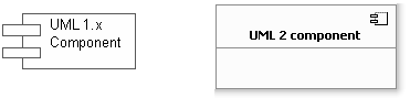
Showing how components can be embedded within other components and how they interface internally within their parent components and externally to other components also is enhanced in version 2.0. With the new notation in this version, you can show the interfaces that a component requires and those it provides to other components. This new notation, illustrated in Figure 8-9, looks much like a “ball and socket.” The ball fits into the socket and is provided visually in the notation. The ball indicates an interface that the component provides, and the socket indicates an interface that the component needs. When you put them together with another component, you complete the communication link between the components.
Figure 8-10 shows a component and the ball and socket as it pertains to a single component. Figure 8-11 shows how you would wire these components together using the new notation to create the Store component. In Figure 8-11, the Product component provides an interface (ball) named OrderableItem. The Order component requires (socket) the OrderableItem interface.
Figure 8-10. Interfaces available from a component.
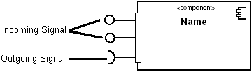
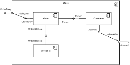
You can also see in Figure 8-11 two small squares on the outer edge of the Store component. Those squares are called ports, and they show an interaction point between the component and other external elements and also between the component and its internal parts. They serve to separate the component from its environment. All interactions with the component take place through its ports. The ball and socket icons attached to the ports show the interfaces that a component provides to or requires from its environment (respectively).
Changes to Class Diagrams
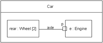
We discuss class diagrams in many chapters in this book—we first introduced them in Chapter 4, “Architectural Modeling,” and then covered them in several chapters thereafter. For the mere mortal, there aren't a lot of relevant changes to class diagrams, but one that is important is structured classes. Structured classes provide the ability to hierarchically decompose a class into an internal structure. They enable a modeler to break down a complex object into its parts. Figure 8-12 shows that whenever an instance of the Car class is created, four instances of the Wheel class are created. In addition, one link each is created between the front wheel instances and the rear wheel instances.
Figure 8-12. Structured class.

Ports and capsules are also used with class instances, just as we discussed in the previous section on component diagrams, to show how class instances are interfaced together in a structured class. Figure 8-13 shows a similar example to Figure 8-12, but adds in the wheel interfacing with the engine.
Figure 8-13. Class instances with interfaces.
UML version 2.0 also features numerous additional changes, including changes to the underlying structures and to the ways you capture metadata, but for mere mortals, and even for many expert modeling practitioners, the changes we highlight here and throughout this book will affect you most in your daily jobs.