12
Building a Complex Software with an Embedded Operating System Flow
In this chapter, you will learn about embedded operating system flows and discover the tools used to build a complex software application to run on an FPGA SoC. You will use the design tools available to create the SoC board support package (BSP) for the desired embedded operating system – in this case, FreeRTOS. You will go through the process of generating the SoC bootloader, which runs when the SoC is powered up and launches the embedded software. This chapter is also hands-on, so you will be guided through every step of the design process. Here, you will go through all the embedded software development phases, starting from the initial concept, followed by the actual software building, and then running it on a hardware board or a virtual platform.
In this chapter, we’re going to cover the following topics:
- Embedded OS software design flow for Xilinx FPGA-based SoCs
- Customizing and generating the BSP and the bootloader for FreeRTOS
- Building a user application and running it on the target
Technical requirements
The GitHub repo for this title can be found here: https://github.com/PacktPublishing/Architecting-and-Building-High-Speed-SoCs.
Code in Action videos for this chapter: http://bit.ly/3WHLVJd.
Embedded OS software design flow for Xilinx FPGA-based SoCs
In Chapter 8, FPGA SoC Software Design Flow, we covered the design flow of a piece of bare-metal embedded software targeting the Electronic Trading System (ETS) SoC. In this chapter, we will go over the steps required to build a Real-Time Operating System (RTOS)-based software application targeting an FPGA SoC. We will perform the entire design flow within the Vitis environment and choose FreeRTOS as the embedded operating system (OS). The design flow can start from a hardware design previously performed in the Vivado environment that has been exported as an XSA archive file (such as the ETS SoC design example). This is then chosen in the Vitis IDE as hosting hardware for the SoC. An alternative method is to choose a Zynq-7000 SoC demo board as the target hardware and perform the necessary steps to create the required framework, as will be detailed in this chapter. Follow these steps to design a FreeRTOS-based SoC software:
- Launch the Vitis IDE from within the Linux Virtual Machine environment using the following command:
$ sudo /<install path of Vitis>/Xilinx/Vitis/2022.1/bin/vitis
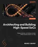
- Once the Vitis IDE is up and running, go to File | Create new platform project. The following wizard will open. Give the new platform a name, such as RTOS_SoC:
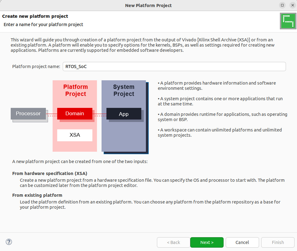
Figure 12.1 – Creating a new platform project in the Vitis IDE
- Click Next to open the Platform window, then click Browse. This will open the Create Platform from XSA menu. Select zc702.xsa, then click Open:
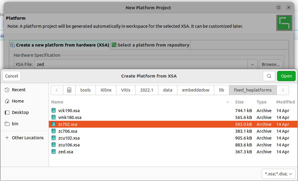
Figure 12.2 – Creating a new platform project from XSA in the Vitis IDE
- Set Operating system to the FreeRTOS port (freertos10_xilinx) and Processor to the Cortex-A9 Core 0 (ps7_cortexa9_0), as shown in the following screenshot. Make sure that you tick the Generate boot components option. Then, click Finish:

Figure 12.3 – Selecting the OS and the processor for the new platform project in the Vitis IDE
- The RTOS_SoC platform project will be created and added to the project in the Vitis IDE, as shown in the following screenshot:
Figure 12.4 – Newly created RTOS_SoC platform project in the Vitis IDE
- Now, we can create an application project using the Vitis IDE’s New Application Project wizard, which can be launched by going to File | New Application Project. Once it has launched, click Next:
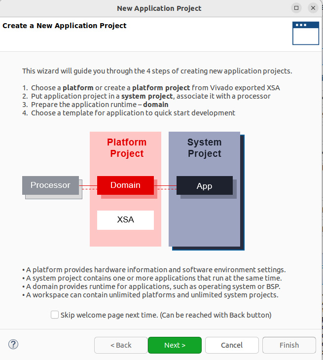
Figure 12.5 – Launching the New Application Project wizard in the Vitis IDE
- In the following window, select the RTOS_SoC [custom] platform, as shown in the following screenshot, and click Next:
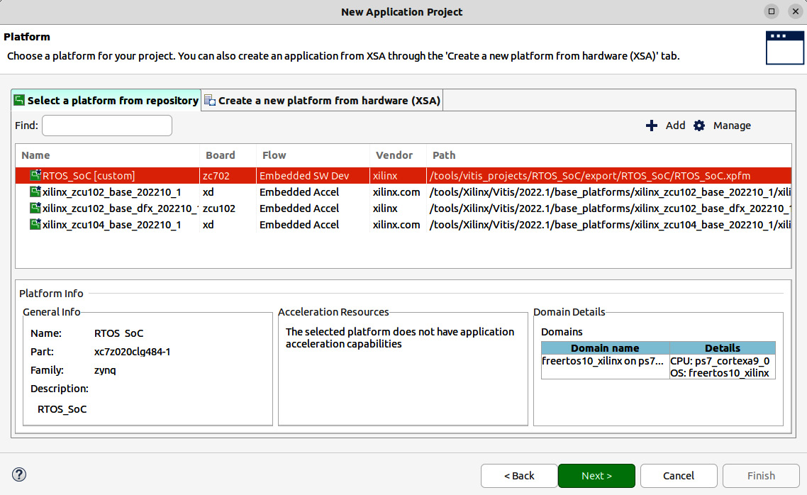
Figure 12.6 – Specifying the platform for the new application project in the Vitis IDE
- Now, specify the Application project name property, as shown in the following screenshot. This will automatically assign it to the Cortex-A9 core 0, which is fine in this case. Then, click Next:
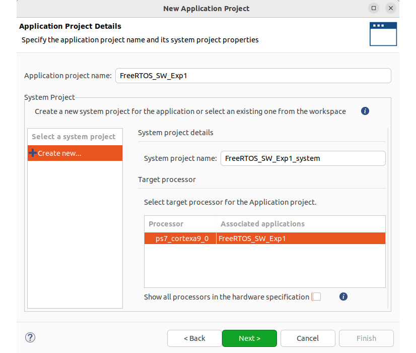
Figure 12.7 – Specifying the new application project name in the Vitis IDE
- Next, we need to select the domain for the application project. Since we only have a single domain (freertos10_xilinx on ps7_cortexa9_0) in this project, leave the default values as-is and click Next:
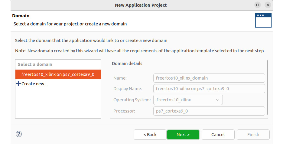
Figure 12.8 – Specifying the domain to associate with the new application project
- Now, you can choose a template application project to start with. Here, select the FreeRTOS Hello World application since this is a good learning example to gain familiarity with simple multi-tasking and message passing between tasks. Then, click Finish:
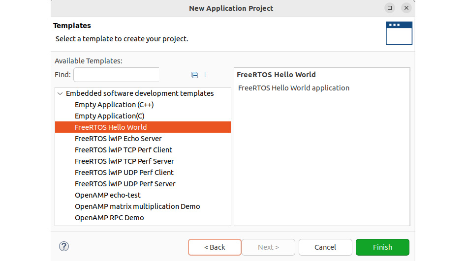
Figure 12.9 – Selecting the FreeRTOS Hello World template for the application project
- The FreeRTOS application project, including the design template, will be added to the Vitis Explorer list, as shown here:
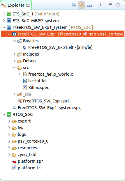
Figure 12.10 – FreeRTOS application project added in Vitis Explorer
With that, we have generated the BSP, the bootloader, and the FreeRTOS application projects. Next, we will delve into the BSP and the bootloader, before examining the application software building process in the last section of this chapter.
Customizing and generating the BSP and the bootloader for FreeRTOS
It is important to understand the layout of an RTOS-based software implementation of an FPGA-based SoC and its different components within the Vitis environment. We know from the previous chapter that on Power-on-Reset (PoR) or following a global system reset, the Cortex-A9 core 0 processor boots from the BootROM in a secure way. Depending on the security settings, a secure boot is started if instructed to do so; if not, a Non-Secure (NS) boot takes place. However, under whichever specified boot mode (secure or NS) by eFuse or the Battery-Backed RAM (BBRAM), the First Stage Boot Loader (FSBL) is the next image to be loaded by the BootROM from Non-Volatile Memory (NVM) NAND, NOR, or QSPI Flash. We also know that an FPGA bitstream can optionally be loaded from the NVM and prepared for configuring the FPGA logic according to the security settings. Finally, it is the FSBL that decides what other images to load from NVM and how to prepare them according to the system security settings. These images include the application software to run on the SoC. Also, running software on FreeRTOS requires the use of a specific BSP that Xilinx has ported using the FreeRTOS packages and its own libraries, as well as the IP drivers used in the design. The Vitis IDE automates a lot of customization under the hood and lets you choose the components you want services from, as well as the minimum required to boot FreeRTOS and run its services on the FPGA SoC. The following steps will show you how to create the BSP for our FreeRTOS application project, as well as provide an insight into its visual structure and included components that we can customize if needed by our end application:
- Recall that in Step 4 of the previous section, we ticked the Generate boot components option, as shown in Figure 12.3. This selection is crucial to create the necessary boot applications and associated components to be able to start the Cortex-A9 and the SoC properly to run FreeRTOS after the PoR or a global system reset. Once the RTOS_SoC platform project has been created and added to the project in the Vitis IDE, the boot project (zynq_fsbl) is created, including its BSP, as shown in the following screenshot. We have also created the BSP for the FreeRTOS application project.
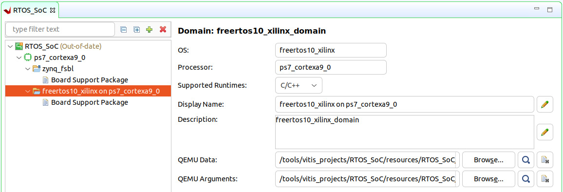
Figure 12.11 – BSPs for the FSBL and FreeRTOS application projects
- As we explored in Chapter 8, FPGA SoC Software Design Flow, for bare-metal applications, we can explore the FreeRTOS BSP components and customize them when necessary. The following screenshot shows the BSP and the Vitis interface to modify it:
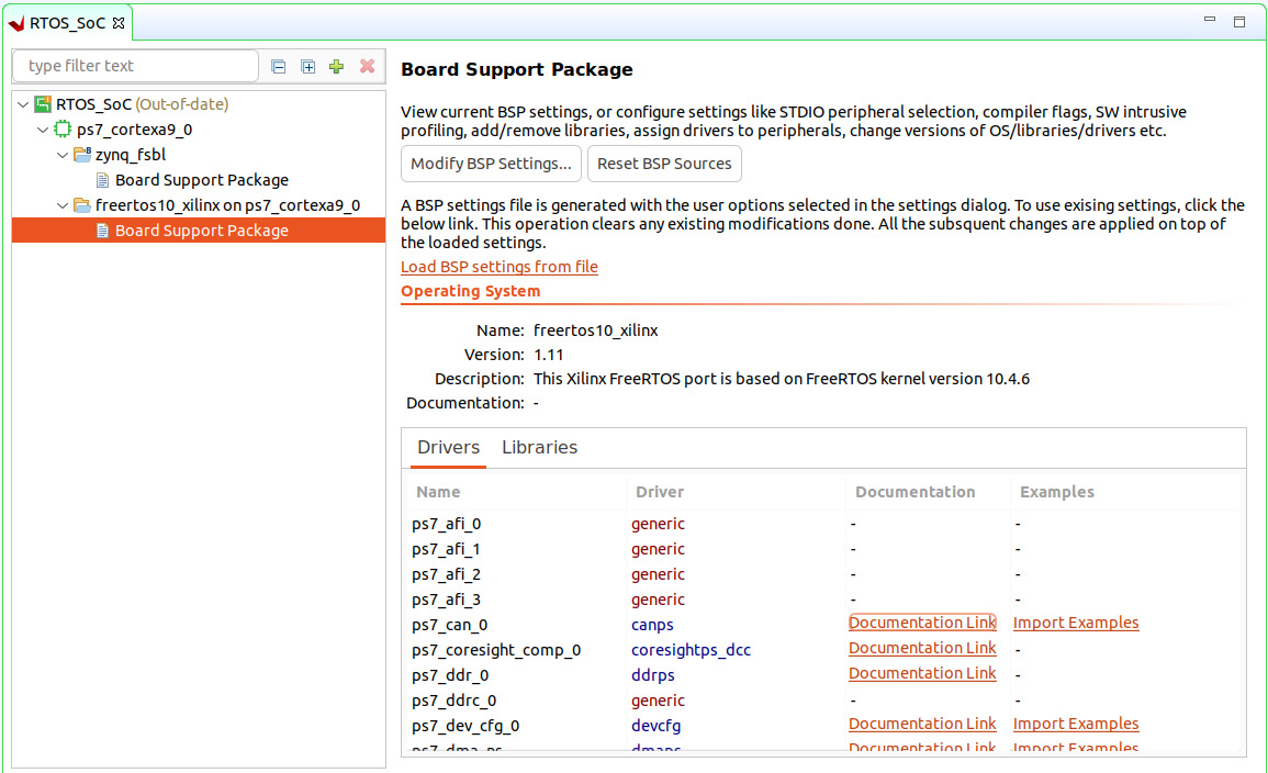
Figure 12.12 – BSPs for the FreeRTOS application project summary
- Click Modify BSP Settings… to enter the Vitis FreeRTOS BSP customization interface. The Board Support Package Settings window will open. Explore the different components and leave everything as-is by default in Vitis for the FreeRTOS Hello World application example:
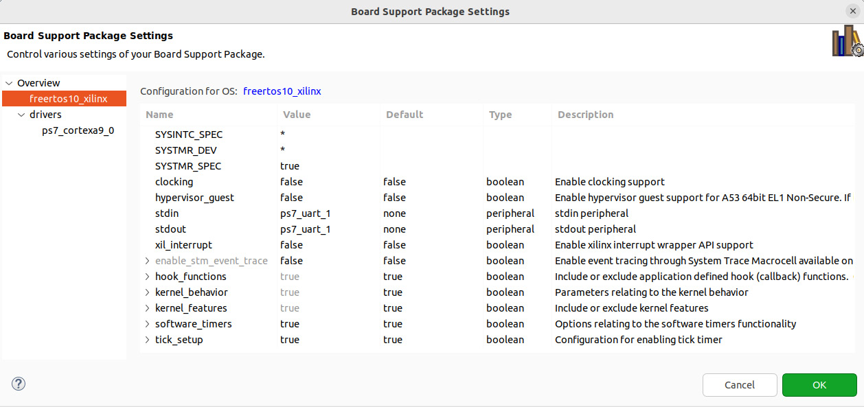
Figure 12.13 – The Board Support Package Settings window
- Now, we can generate the BSPs for both the bootloader and the FreeRTOS application projects. In the Vitis IDE’s Explorer window, right-click the RTOS_SoC domain entry and click Build project, as shown in the following screenshot:

Figure 12.14 – Building the BSP components for FSBL and FreeRTOS
This will generate the necessary FSBL components and libraries required by the application building process for FreeRTOS.
Building a user application and running it on the target
Now, we will build the FreeRTOS Hello World application and run it on the virtual platform within the Vitis IDE. By doing so, we can revisit the application template source code and build upon it so that it matches our software requirements. For the ETS SoC project, we can generate another FreeRTOS application based on a UDP client template provided by the Vitis project creation wizard and use it as a starting example. It is by itself a proper software project that requires modifying the Xilinx Ethernet drivers so that they match the microarchitecture requirements of our design. We have access to the driver’s source code and the UDP client template to achieve this. As an exercise for any embedded software developers using this book, it can be a nice challenge to implement the software design presented in Chapter 8, , FPGA SoC Software Design Flow, by using the knowledge you’ve accumulated thus far. From the Electronic Trading Market (ETM) side, the User Datagram Protocol (UDP) server example can be used as a starting template, though any other UDP server software from the open source community can be implemented on a Linux host to act as the ETM and provide the UDP streams as per the defined ETM protocol.
To build the FreeRTOS software application in the Vitis IDE and run it on the virtual platform, follow these steps:
- Right-click the FreeRTOS_SW_Exp1 project entry under FreeRTOS_SW_Exp1_system and click Build. We will use the default project settings set by the Vitis IDE for this template software application project:
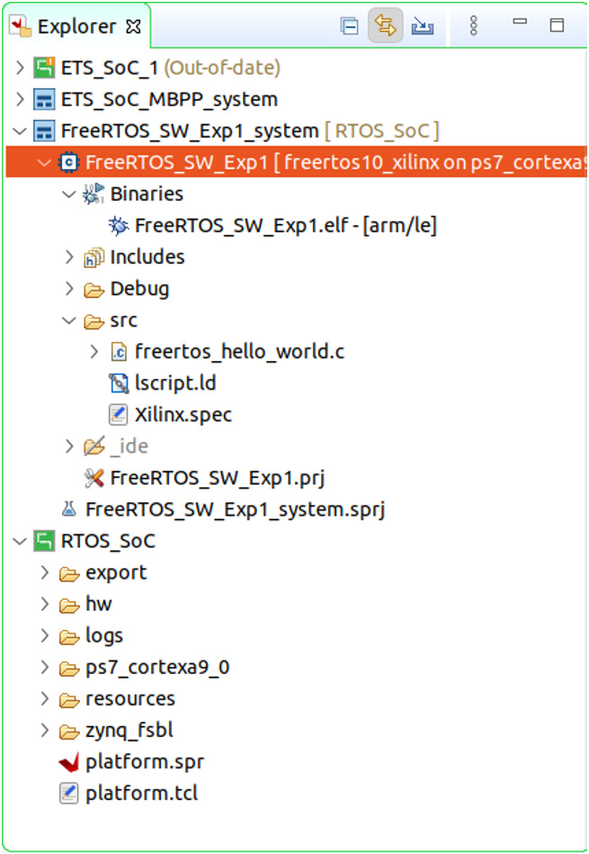
Figure 12.15 – Building the FreeRTOS project application
- The compiler will run all the necessary steps and build all the required object files to generate the FreeRTOS software executable image, as shown in the Vitis Console window. The application executable image is around 171 KB:
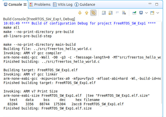
Figure 12.16 – Vitis IDE console showing the FreeRTOS software image being built
- Let’s launch the virtual platform emulator and run the FreeRTOS application software we have just built for it. Right-click the FreeRTOS_SW_Exp1 project entry, select Run As, and then select 2 Launch SW Emulator (Single Application Debug):
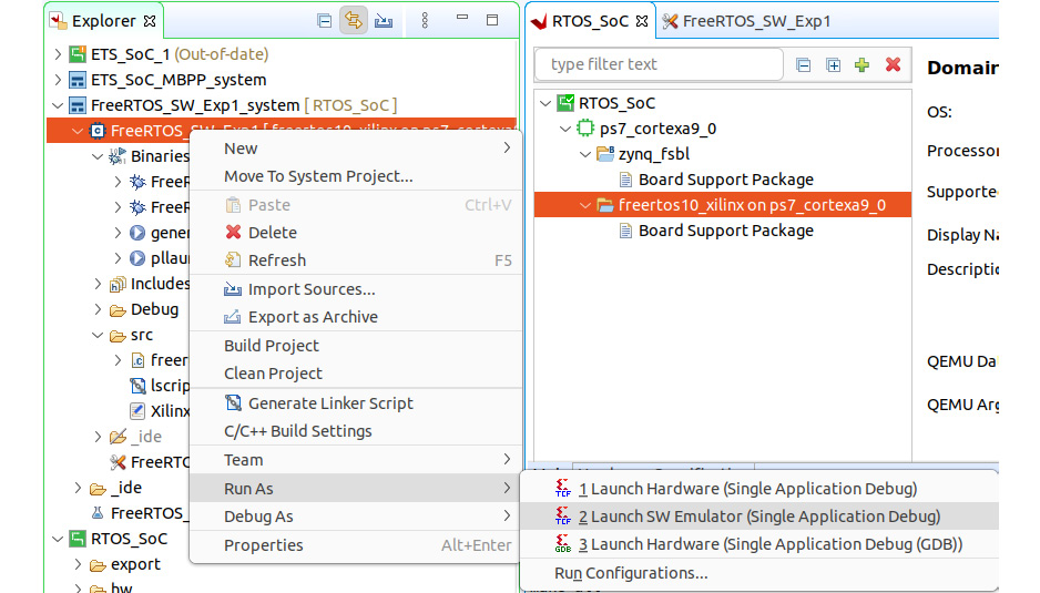
Figure 12.17 – Launching the FreeRTOS application image on the virtual platform in the Vitis IDE
- This will automatically launch the QEMU-based virtual platform in the Vitis IDE, boot the Zynq-7000 SoC, and load the FreeRTOS software application, as shown here:
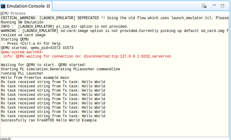
Figure 12.18 – Running the FreeRTOS application image on the virtual platform in the Vitis IDE
The FreeRTOS Hello World application will run on the virtual platform to completion, as shown in the preceding screenshot.
This will complete the complex software design flow in the Vitis IDE, from the initial platform specification to running the FreeRTOS application generated as a template by the Vitis IDE. In this example, we used the Vitis-included QEMU virtual platform, which will help greatly in learning the details of developing an RTOS-based embedded software for advanced high-speed SoCs targeting the Xilinx Zynq-7000 SoC FPGAs.
Summary
In this chapter, we looked at the key steps required to build a complex RTOS-based software application and specifically its associated software design flow within the Vitis IDE. We covered all the steps required in this process. We also looked at the platform generation using an existing XSA file for a known demo board to generate a platform and its associated project domain. Then, we learned how to generate a software application associated with the created domain and showed the necessary settings for the FreeRTOS embedded OS. We also generated an application software project example to run on FreeRTOS. We delved into the bootloader topic and how to create and customize the BSP for both the FSBL and FreeRTOS software application projects. Then, we built and ran these software projects on the QEMU virtual platform within the Vitis IDE. The output loggings from the software application on the QEMU console echoed a successful software application run.
In the next chapter, we will explore more topics related to FPGA-based SoC advanced applications with a focus on digital signal, image, and video processing.
Questions
Answer the following questions to test your knowledge of this chapter:
- What is an RTOS?
- What should be done to specify the ETS SoC hardware design as the target platform for FreeRTOS-based software projects?
- What is a BSP? List its components.
- How can we generate the boot components for the FreeRTOS project in the Vitis IDE?
- List the required steps for generating a LwIP Perf UDP client FreeRTOS-based software application.
- List the steps for customizing the BSP.
- What is an FSBL? When is it involved?
- Describe the steps performed by the FSBL we generated for the RTOS_SoC platform.
- List the steps you must follow to build the FreeRTOS software example.
- How can we target the QEMU virtual platform to run FreeRTOS-based software projects in the Vitis IDE?