
2
Securing Azure Networks
In the previous chapter, we covered recipes that provided the foundation for securing Azure AD identities.
We should consider Zero Trust and defense in depth to be cornerstones of a cloud security strategy. We must consider the network as untrusted and assume a breach.
In this chapter, we build on those foundations and go through recipes that will equip us with the skills for securing Azure networks.
We will take a look at the protection of the network from the Open Systems Interconnection (OSI) model perspective and focus on solutions to protect Layer 3 (Network), Layer 4 (Transport), and Layer 7 (Application).
By the end of this chapter, you will have gained valuable skills for securing Azure networks through the following recipes:
- Implementing network security groups
- Implementing Azure Firewall
- Implementing Azure Web Application Firewall
- Implementing Azure DDoS
Technical requirements
For this chapter, it is assumed that you have an Azure AD tenancy and an Azure subscription after completing the recipes in the previous chapter of this cookbook. If you skipped straight to this chapter, the information to create a new Azure AD tenancy and an Azure subscription for these recipes is included in the following list of requirements.
For this chapter, the following are required for the recipes:
- A device with a browser, such as Edge or Chrome, to access the Azure portal: https://portal.azure.com
- An Azure AD tenancy and Azure subscription; you may use an existing one or sign up for free: https://azure.microsoft.com/en-us/free
- An Owner role for the Azure subscription
Implementing network security groups
As part of an in-depth defense strategy, you should implement measures to protect your workload resources and filter network traffic between resources in your Azure virtual networks. Network Security Groups (NSG) can offer protection against lateral movement threats.
This recipe will teach you how to implement NSGs to protect your Azure virtual network virtual machine resources.
We will take you through creating a virtual network and a workload server virtual machine resource to protect. Then, we will walk through creating an NSG and apply it to the virtual network subnet where the test workload server virtual machine is located to demonstrate providing both allow and deny controls.
Getting ready
This recipe requires the following:
- A device with a browser, such as Edge or Chrome, to access the Azure portal: https://portal.azure.com
- You should sign in with an account that has the Owner or Contributor role for the Azure subscription
- An Azure virtual machine to use with this recipe; we will walk through creating this virtual machine as a getting ready task:
- This will be created without an NSG attached to its network interface or the virtual machine’s subnet
- This will not have a public IP address associated with its network interface
Continue with the following getting ready task of creating a virtual machine for this recipe.
Getting ready task – creating a virtual machine
- In the search box in the Azure portal, type virtual machines and select Virtual machines from the listed Services results:
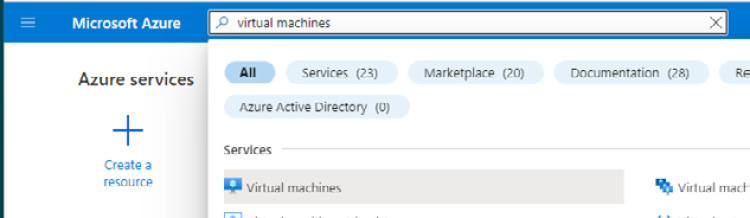
Figure 2.1 – Search for virtual machines
- On the Virtual machines screen, click + Create and then select Azure virtual machine:

Figure 2.2 – Virtual machines screen
- From the Basics tab, under the Project details section, set the subscription as required.
- For Resource group, select Create new.
- Enter a name and click OK.
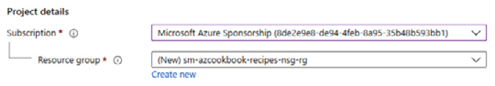
Figure 2.3 – Create a new resource group
- Set the following:
- Virtual machine name: Type a name
- Region: Select a region
- Availability options: Select No infrastructure redundancy required
- Security type: Select Standard
- Image: Select Windows Server 2019 Datacenter - Gen2
- Size: Leave the default (or set it as required to reduce recipe costs)
- Username and Password: Set as required
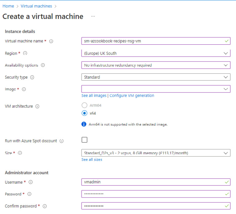
Figure 2.4 – Create a virtual machine
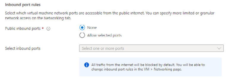
Figure 2.5 – Set Public inbound ports
- Click Next : Disks, leave the defaults, then click Next : Networking.
- From virtual network, click Create new.
- On the Create virtual network screen, enter a name:

Figure 2.6 – Create virtual network
- For Address space, leave the default.
- Under Subnets, change the listed default subnet name from default to Workload-Subnet; then, click OK:
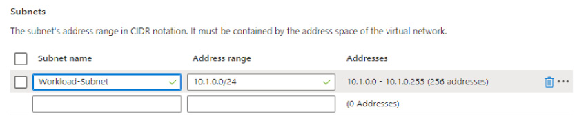
Figure 2.7 – Subnet settings
- Set Public IP to None and NIC network security group to None, and tick to enable Delete NIC when VM is deleted:

Figure 2.8 – Network interface settings
- Click Review + create.
- Click Create on the Review + create tab.
A notification will display that the resource deployment succeeded.
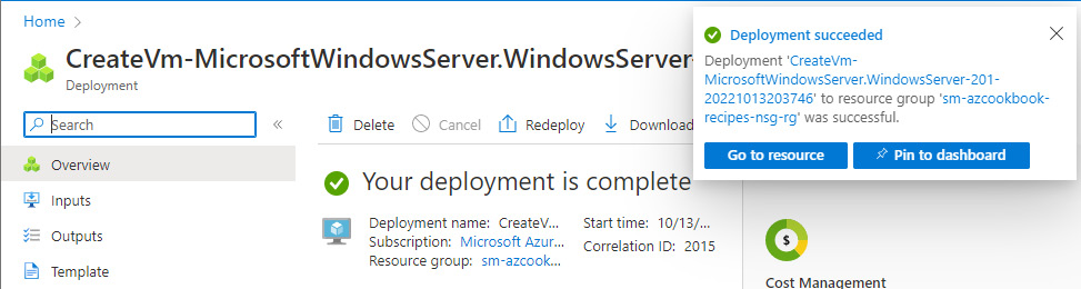
Figure 2.9 – Deployment completed notification
This getting ready task to create a virtual machine for this recipe is complete.
You are now ready to continue on to the main tasks of this recipe for implementing an NSG.
How to do it…
This recipe consists of the following tasks:
- Create an NSG.
- Associate the NSG with a subnet.
- Add and test an inbound rule.
- Add and test an outbound rule.
- Clean up resources.
Task – creating an NSG
Perform the following steps:
- In the search box in the Azure portal, type network security groups and select Network security groups from the listed Services results:
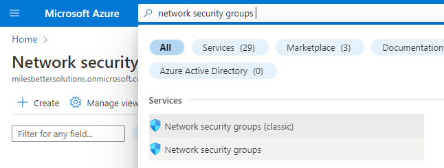
Figure 2.10 – Search for network security groups
- On the Network security groups screen, click + Create.
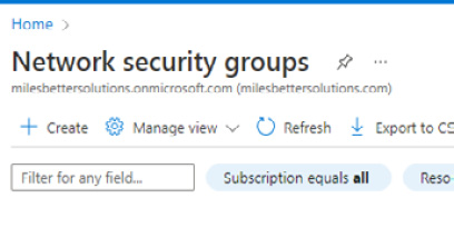
Figure 2.11 – Network security groups screen
- From the Basics tab, set Subscription and Resource group to the same values that you set for your virtual machine in the Getting ready section.

Figure 2.12 – Project details
- Set Name as required and Region to the same as you set for your virtual machine.
- Click Review + create.
- Click Create on the Review + create page.
- Once the deployment is complete, click on Go to resource.

Figure 2.13 – Deployment completed notification
The task to create an NSG is complete. We will associate the created NSG with a subnet in the next task.
Task – associating the NSG with a subnet
- From the created NSG screen, click Subnets under the Settings section on the left menu.
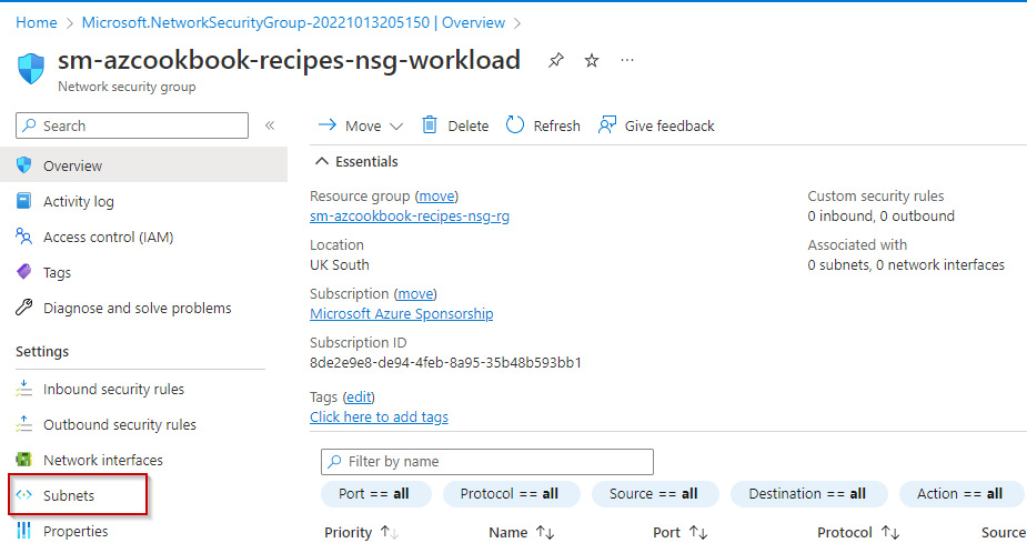
Figure 2.14 – NSG

Figure 2.15 – Subnets screen
- In the Associate subnet blade, select the virtual network and subnet of the virtual machine created in the previous task, then click OK.
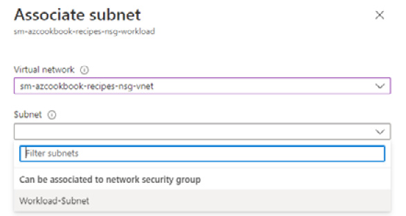
Figure 2.16 – Associate subnet
A notification will display that the changes were saved successfully.
The task to associate an NSG with a subnet is complete. In the next task, we add an inbound rule and test it.
Task – adding and testing an inbound rule
Perform the following steps:
- Navigate to the NSG created in this recipe. Notice that all inbound connections are denied unless their source is VirtualNetwork or Azure LoadBalancer. We will address this in the next task.
- In the Network security group blade, click Inbound security rules under Settings.
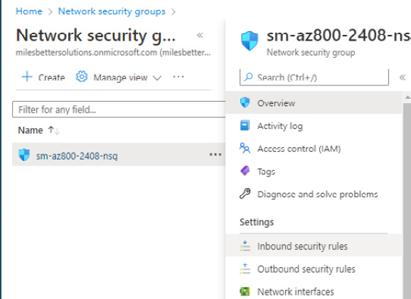
Figure 2.17 – Network security group

Figure 2.18 – Inbound security rules
- Open a browser; in your chosen search engine, type what's my IP and note your IP address.
- In the Add inbound security rule blade, set the following:
- Source: Select IP Addresses
- Source IP addresses/CIDR ranges: Set this to your IP address as discovered in step 4 of this task
- Source port ranges: Leave the default of * (asterisk symbol)
- Destination: Leave the default of Any
- Service: Select RDP
- Action: Ensure Allow is set
- Priority: Leave the default of 100
- Name: Provide a name, such as AllowInbound_RDP_KnownIP
- Description: Type as required
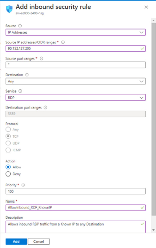
Figure 2.19 – Add inbound security rule
Figure 2.20 – Security rule created
- Navigate to the Virtual machines screen, click on your virtual machine, and from the Overview blade of your virtual machine, click on Connect and then RDP.

Figure 2.21 – Virtual machines
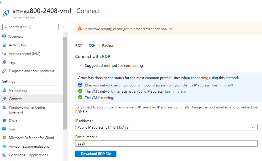
Figure 2.22 – Connect blade
- Open the RDP file from where it was saved.
- Click Connect to start an RDP session allowed by the inbound rule set in this task.
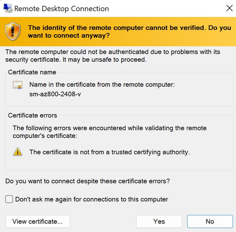
Figure 2.23 – Remote Desktop Connection
In this task, we added an inbound rule and completed our test of it. In the next task, we will create an outbound rule and test it.
Task – adding and testing an outbound rule
- In the Virtual machine blade, click Networking under Settings; you will see from the Outbound port rules tab that all outbound connections are allowed to the internet.
- From the Outbound port rules tab, click Add outbound port rule.
- In the Add outbound security rule blade, leave all options as the defaults apart from the following:

Figure 2.24 – Add security rule
- Click Add. You will receive a notification that the rule was created successfully.
- From the virtual machine, open a browser again and confirm you can no longer reach the internet by visiting a site such as https://learn.microsoft.com.
- This time, you will see a message from the browser, such as can’t reach this page.
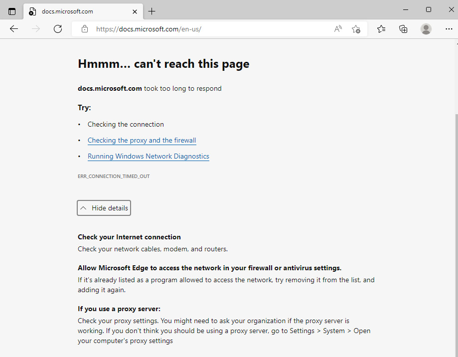
Figure 2.25 – Internet access denied
The task to create an outbound rule is complete. In the next task, we will clean up the resources created in this recipe.
Task – cleaning up resources
- In the search box in the Azure portal, type resource groups and select Resource Groups from the listed Services results.
- From the Resource groups page, select the resource group we created for this recipe and click Delete resource group; this will delete all the resources created as part of this recipe.

Figure 2.26 – Delete resource group
The task to clean up the resources created in this recipe is complete.
How it works…
In this recipe, we looked at creating an NSG and associated it at the subnet level. We then added rules to allow RDP access on port 3389 from a specified source IP address to a Windows Server virtual machine resource. We also added a rule to deny all outbound internet access. We also provided a step-by-step guide on creating a virtual network and a virtual machine to test these rules.
NSGs act as traffic filters and can be used to control traffic flow out of resources in a virtual network. NSGs contain rules like a traditional firewall that allow or deny inbound and outbound traffic; all traffic is denied unless explicitly allowed by a rule.
An NSG can only be associated with resources in the same subscription and region. Azure Firewall is better positioned for centralized protection across subscriptions and regions.
Each rule in an NSG is numbered; the lowest-numbered rule will be processed first. There is a set of default rules for each NSG that cannot be removed or modified. To override these rules, you add custom rules with a lower number, which are processed first. There is a deny-all final default rule that will be processed. That is, if your connection request is not explicitly allowed by a lower-number rule, then the connection will be denied.
Whether access is allowed or denied is based on the evaluation of the five-tuple method, which is based on the following five data points:
- Traffic source
- Traffic source port
- Traffic destination
- Traffic destination port
- Traffic protocol
The following diagram represents a simple example of traffic control with an NSG:
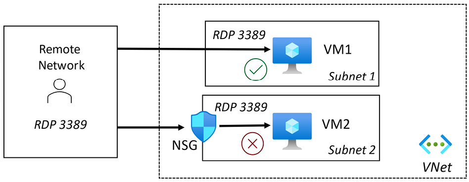
Figure 2.27 – NSG traffic control
In the preceding diagram, no NSG is associated with the subnet that VM1 is connected to. This allows a connection with RDP on port 3389 for a Windows virtual machine (port 22 if Linux). An attacker could brute-force attack this virtual machine using this unsecured management port.
VM2, however, has an NSG associated with the VMs subnet and, by default, will deny all inbound traffic unless explicitly allowed; the virtual machine management port will be protected against brute-force attacks.
To allow access, we must explicitly create a rule that specifies what connection traffic will be allowed.
If required, an NSG can be applied at the subnet or network interface level.
See also
Should you require further information, you can refer to the following Microsoft Learn articles:
- Azure security baseline for Virtual Network: https://learn.microsoft.com/en-us/security/benchmark/azure/baselines/virtual-network-security-baseline
- Network security groups: https://learn.microsoft.com/en-us/azure/virtual-network/network-security-groups-overview
- How network security groups filter network traffic: https://learn.microsoft.com/en-us/azure/virtual-network/network-security-group-how-it-works
- Diagnose a virtual machine network traffic filter problem: https://learn.microsoft.com/en-us/azure/virtual-network/diagnose-network-traffic-filter-problem
- Tutorial: Log network traffic to and from a virtual machine using the Azure portal: https://learn.microsoft.com/en-us/azure/network-watcher/network-watcher-nsg-flow-logging-portal
Implementing Azure Firewall
As part of our defense-in-depth strategy, we should implement measures to protect the perimeters of our Azure virtual networks. In environments with many distributed workload resources that need to communicate securely, we must ensure we protect these across many regions and subscriptions.
We must protect traffic entering our network from the internet (North/South), internal traffic from spoke-to-spoke virtual networks (East/West), and cross-premises hybrid or partner edge connections.
This recipe will teach you how to implement Azure Firewall Premium to protect your resources in an Azure virtual network.
We will take you through creating an Azure Firewall and policy, creating a default route, creating a workload server virtual machine for testing, and configuring and testing firewall rules.
Getting ready
This recipe requires the following:
- A device with a browser, such as Edge or Chrome, to access the Azure portal: https://portal.azure.com
- You should sign in with an account that has the Owner or Contributor role for the Azure subscription
- An Azure virtual machine to use with this recipe; we will walk through creating this virtual machine as a getting ready task:
- This will be created without an NSG attached to its network interface or the virtual machine’s subnet
- This will not have a public IP address associated with its network interface
Continue with the following getting ready task of creating a virtual machine for this recipe.
Getting ready task – creating a workload server virtual machine
- In the search box in the Azure portal, type virtual machines and select Virtual machines from the listed Services results.
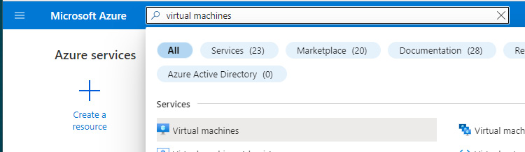
Figure 2.28 – Search for virtual machines
- On the Virtual machines screen, click + Create and then select Azure virtual machine:

Figure 2.29 – Virtual machines
- From the Basics tab, under the Project details section, select a subscription that will be used for resources in this recipe.
- For Resource group, select Create new.
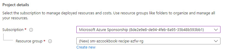
Figure 2.30 – Set project details
- Set Instance details as follows:
- Virtual machine name: Type a name
- Region: Select the same region used to create the Azure Firewall
- Availability options: Select No infrastructure redundancy required
- Security type: Select Standard
- Image: Select Windows Server 2019 Datacenter - Gen2
- Size: Leave the default (or select as required to optimize costs)
- Set Username and Password as required:
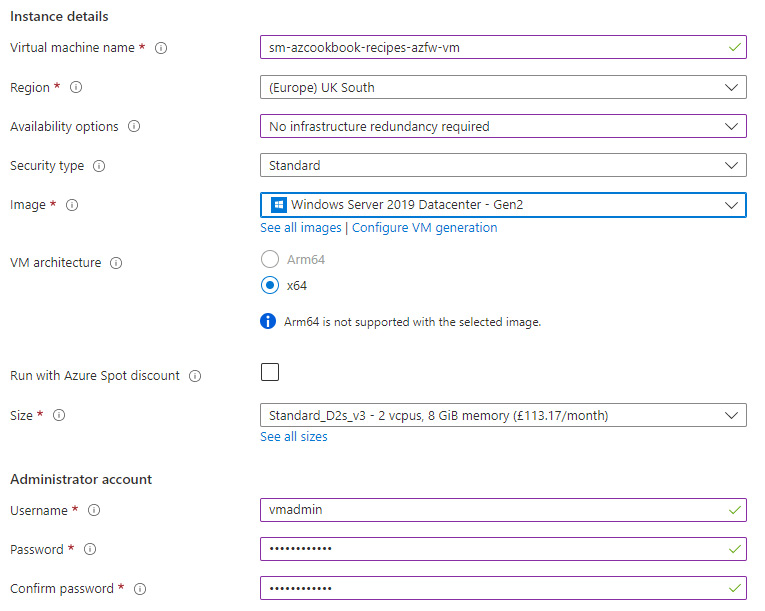
Figure 2.31 – Virtual machine settings
- Set Public inbound ports to None:
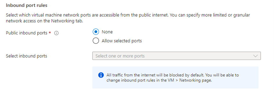
Figure 2.32 – Set Public inbound ports
- Click Next : Disks, leave the defaults, then click Next : Networking.
- In Virtual network, click Create new.
- On the Create virtual network screen, enter a name:

Figure 2.33 – Create virtual machine
- In the Address space section, under the Address range section, on the right-hand side of the provided default Address range entry, click the trash can icon to delete the default address range.
- Type a new address range of 10.10.0.0/16.
- In the Subnets section, for the subnet name, type WorkloadSubnet, and for Address range, type 10.10.1.0/24; then, click OK:

Figure 2.34 – Virtual networks
- Set Public IP to None and NIC network security group to None, and tick to enable Delete NIC when VM is deleted:
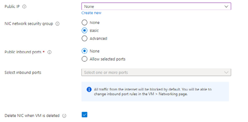
Figure 2.35 – Virtual network settings
- Click Review + create.
- Click Create on the Review + create tab.
- On the screen that notifies you with Your deployment is complete, click on Go to resource to get ready for the next step in this task.

Figure 2.36 – Deployment complete
- For the upcoming task of creating a DNAT rule, we will need to take note of the virtual machine’s private IP; this can be found in the virtual machine’s Overview blade under the Networking section of the Properties tab:
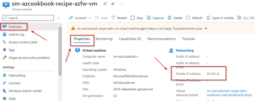
Figure 2.37 – Virtual machine blade
This getting ready task to create a virtual machine for this recipe is complete.
You are now ready to continue to the main tasks for this recipe for implementing Azure Firewall.
How to do it…
This recipe consists of the following tasks:
- Create an Azure Firewall.
- Create a workload server virtual machine for testing.
- Create virtual network peering.
- Create a User-Defined Route (UDR) to the workload subnet.
- Create a DNAT rule to allow RDP access to the workload server virtual machine.
- Create an application rule.
- Clean up resources.
Task – creating an Azure Firewall
- In the search box in the Azure portal, type firewall and select Firewalls from the listed Services results:
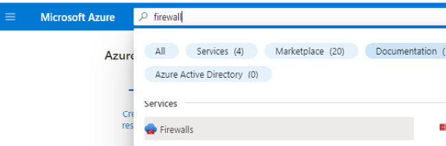
Figure 2.38 – Search for Azure Firewall
- On the Firewalls screen, click + Create or Create firewall:
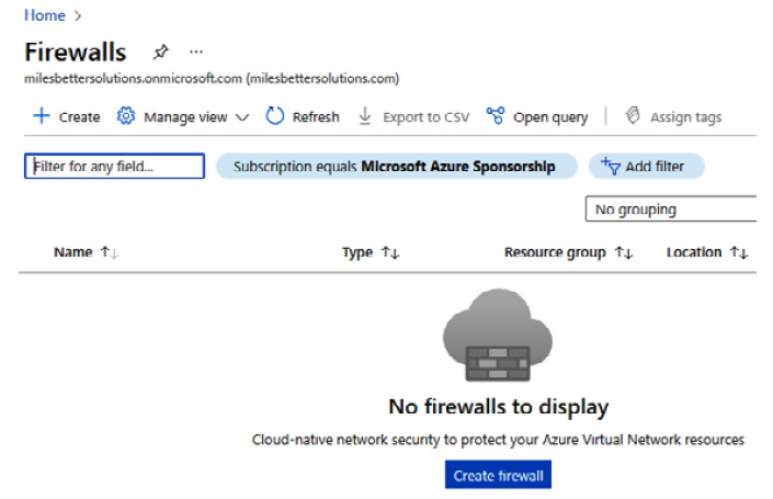
Figure 2.39 – Firewalls screen
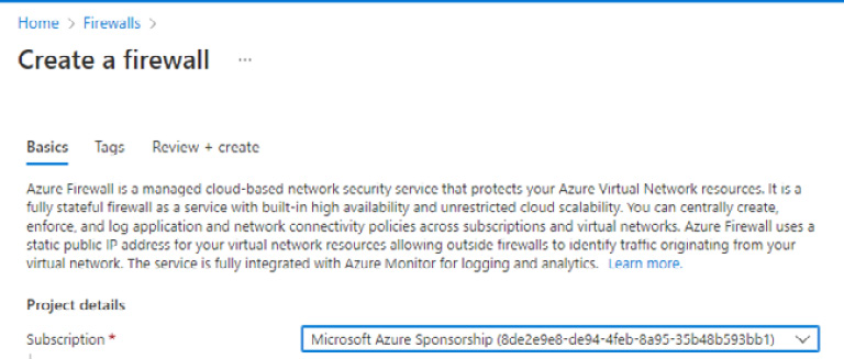
Figure 2.40 – Create a firewall
- For Resource group, click Create new.
- Enter a name and click OK:
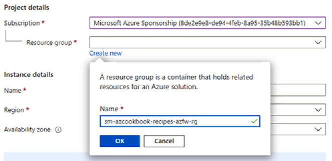
Figure 2.41 – Create a new resource group
- Under the Instance details section, set a name and region as required and set Availability zone to None:
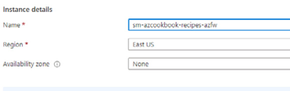
Figure 2.42 – Create firewall settings
- Ensure the Firewall SKU is set to Premium.
- For Firewall policy, click Add new.
- Type a policy name and region as required; ensure Policy tier is set to Premium. Then, click OK:

Figure 2.43 – Create a new Firewall Policy
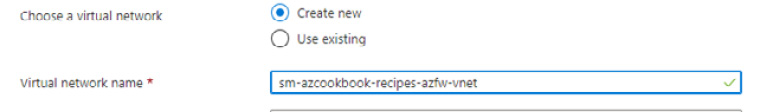
Figure 2.44 – Create a new virtual network
Note
We must ensure we do not overlap any address space used for the workload server virtual machine virtual network.
- For Address space, type 10.0.0.0/16.
- For Subnet address space, type 10.0.0.0/24:

Figure 2.45 – Virtual network settings
- For Public IP address, click Add new; type a name as required, then click OK:
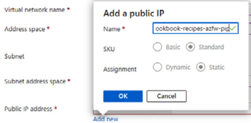
Figure 2.46 – Add a public IP
- Click Review + create.
- Click Create on the Review + create tab.
- On the screen that notifies you with Your deployment is complete, click on Go to resource ready for the next step in this task:
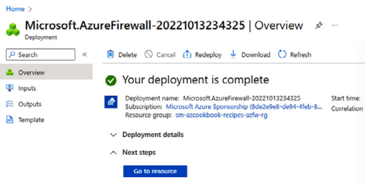
Figure 2.47 – Deployment complete
- For the upcoming tasks of creating a default route and a DNAT rule, we will need to take note of the firewall’s public and private IPs:
- The private IP can be found from the firewall’s Overview blade:

Figure 2.48 – Private IP
- The public IP can be found by clicking on the hyperlinked name for the public IP on the Overview blade, or by clicking on Public IP configuration under the Settings section:

Figure 2.49 – Public IP
The task to create an Azure Firewall is complete. In the next task, we create peering between our two virtual networks.
Task – creating virtual network peering
- Navigate to the Virtual networks screen and you should see both virtual networks we created in this exercise; note that they are in the same subscription and region for this recipe.
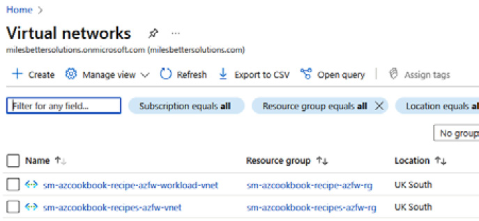
Figure 2.50 – Virtual networks blade
- Click your Azure Firewall virtual network, sm-azcookbook-recipes-azfw-vnet.
- From the Virtual networks blade, click Peerings under the Settings section of the left-hand menu:
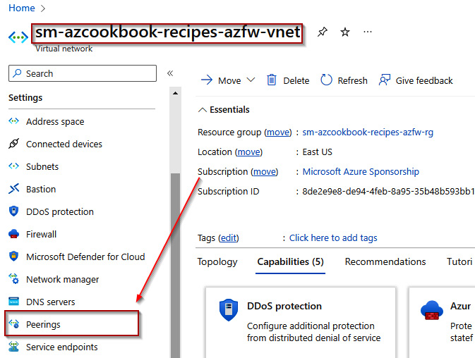
Figure 2.51 – Virtual networks blade
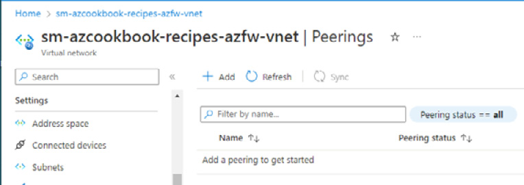
Figure 2.52 – Peerings blade
- Enter a peering link name under the This virtual network section:
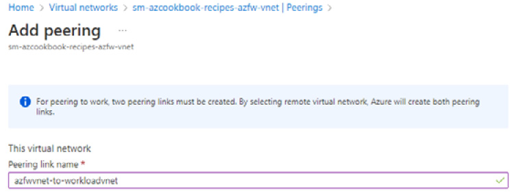
Figure 2.53 – Peering name for this virtual network

Figure 2.54 – Peering name for remote virtual network
- Select the same subscription used for previous tasks in this recipe; for Virtual network, select the workload virtual network we created that contains our workload server virtual machine, then click Add:

Figure 2.55 – Add peering
You will see a notification that the peering was successfully added:

Figure 2.56 – Peering added
The task to create peering between virtual networks is complete. In the next task, we create a UDR.
Task – creating a user-defined route
- In the search box in the Azure portal, type route table and select Route tables from the listed Services results:
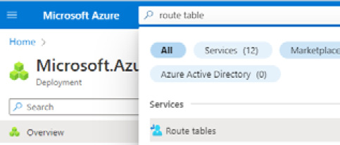
Figure 2.57 – Search for route table
- On the Route tables screen, click + Create or Create route table:
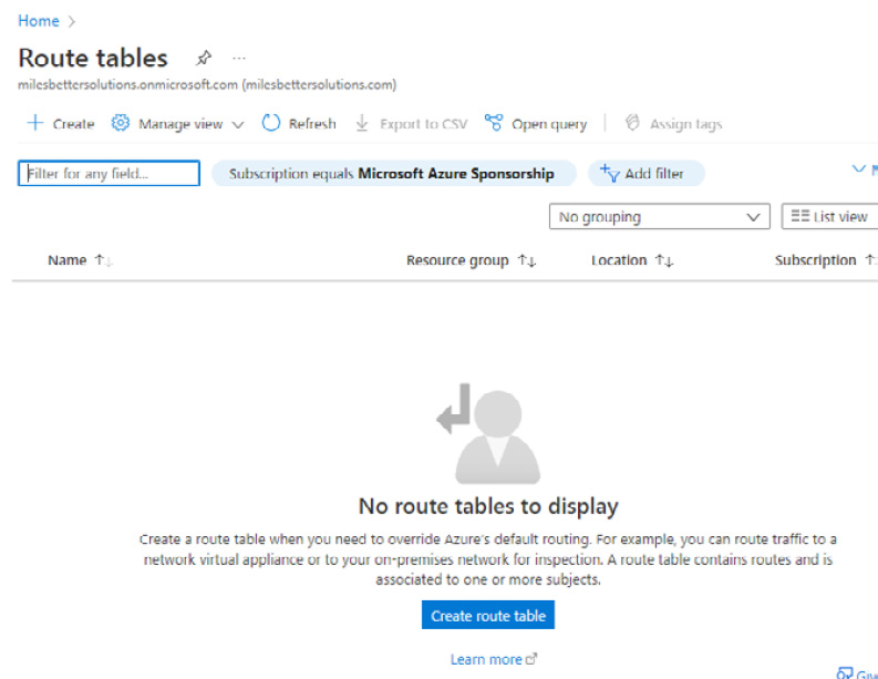
Figure 2.58 – Route tables screen
- From the Basics tab, in the Project details section, select the same subscription used for the previous tasks in this recipe.
- For Resource group, select the same one used for the previous tasks in this recipe:
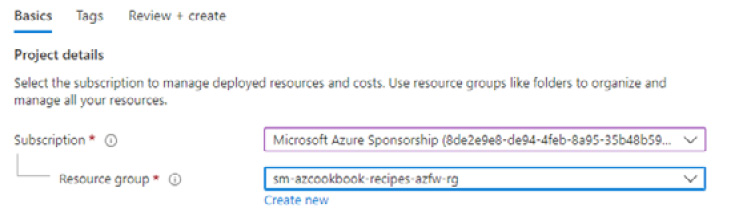
Figure 2.59 – Set project details
- Select the same region as used for the previous tasks in this recipe; then, type a name as required:

Figure 2.60 – Set instance details
- Click Review + create.
- Click Create on the Review + create tab.
- Click Go to resource on the Deployment screen that notifies you that the deployment is complete:

Figure 2.61 – Deployment completed
- Click Subnets under the Settings section on the Route table screen, then click + Associate:

Figure 2.62 – Associate route table
- For Virtual network on the Associate subnet blade, select your workload virtual network created for this recipe; then, select Workload-Subnet from the Subnet list and click OK:
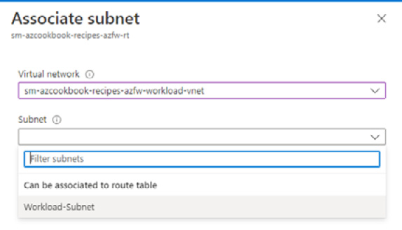
Figure 2.63 – Associate subnet
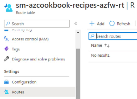
Figure 2.64 – Add route
- In the Add route blade, add a route name to represent the default gateway for the workload subnet and select IP Addresses for Address prefix destination:

Figure 2.65 – Add route
- For Destination IP addresses/CIDR ranges, type 0.0.0.0/0.
- For Next hop type, select Virtual appliance:
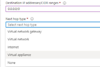
Figure 2.66 – Route table configuration
- For Next hop address, type Azure Firewall’s private IP that we noted at the beginning of this task; for reference, this can be found in the Overview blade of your firewall. Then, click Add:

Figure 2.67 – Route table configuration
- A notification will display that you successfully added a route:
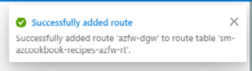
Figure 2.68 – Added route
The task to create a UDR is complete. In the next task, we create a Destination Network Address Translation (DNAT) rule.
Task – creating a DNAT rule
- Navigate to your created Azure Firewall in the Azure portal, and in the Overview blade of your firewall, under Firewall policy, click your policy to open the Firewall Policy screen:
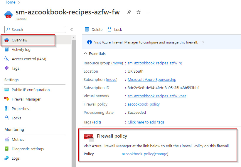
Figure 2.69 – Azure Firewall
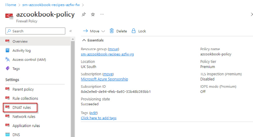
Figure 2.70 – Azure Firewall policy
- Click + Add a rule collection:

Figure 2.71 – Add rule
- On the Add a rule collection blade, set the following:

Figure 2.72 – Add a rule collection
- In the Rules section, set the following:
- Type a name as required for the first rule in the rule collection
- For Source type, ensure IP Address is selected
- For Source, type *
- For Protocol, select TCP
- For Destination Ports, type 3389
- For Destination Type, ensure IP Address is selected
- For Destination, enter the Firewall public IP address we noted in an earlier task in this recipe
- For Translated address, enter the workload server virtual machine private IP address we noted in an earlier task in this recipe
- For Translated port, type 3389
You should now have a rule that looks like the following:
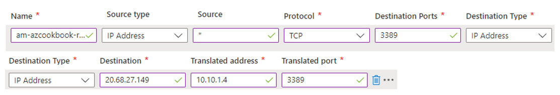
Figure 2.73 – Firewall rule
- Click Add. You will be notified that the rule collection was successfully added in a few minutes:
Figure 2.74 – Added rule collection
The task to create a DNAT rule is complete. In the next task, we create an application rule.
Task – creating an application rule
Perform the following steps:
- Navigate to the created Azure Firewall in the Azure portal, and in the Overview blade of your firewall, under the Firewall policy section, click your Firewall policy to open the Firewall Policy screen:

Figure 2.75 – Azure Firewall
- On the Firewall Policy screen, click Application rules under the Settings section:
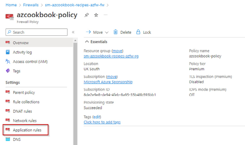
Figure 2.76 – Firewall Policy
- Click + Add a rule collection.
- On the Add a rule collection blade, set the following:
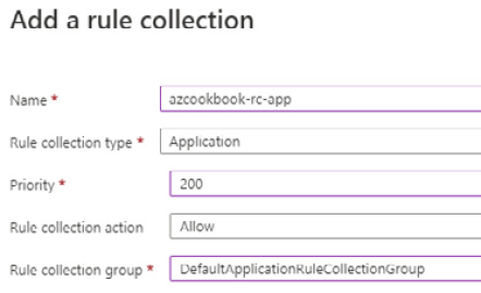
Figure 2.77 – Add rule collection
- In the Rules section, set the following:
- Type a name as required for the first rule in the rule collection
- For Source type, ensure IP Address is selected
- For Source, type *
- For Protocol, select https
- For Destination Type, select FQDN
For Destination, type learn.microsoft.com
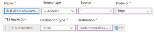
Figure 2.78 – Firewall rule
- Click Add. You will be notified that the rule collection was successfully added in a few minutes:
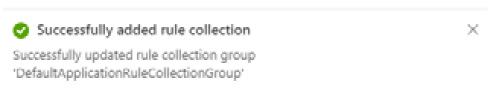
Figure 2.79 – Added rule collection
The task to create an application rule is complete. In the next tasks, we test the firewall rules.
Task – testing the firewall DNAT rule
- Open Remote Desktop Connection and set it to the firewall’s public IP address:
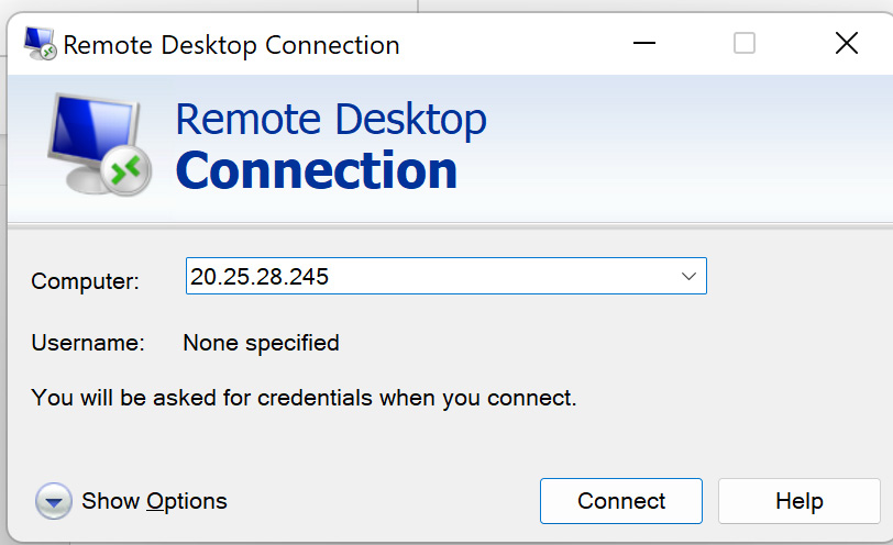
Figure 2.80 – Remote Desktop Connection
- You will be prompted with the workload server virtual machine login credentials:
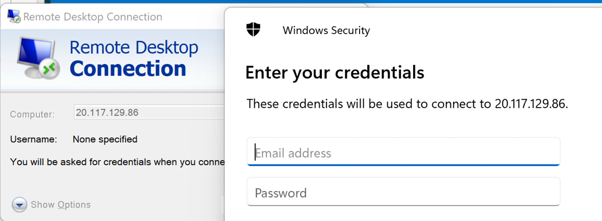
Figure 2.81 – Access to workload server virtual machine

Figure 2.82 – Logged on to workload server virtual machine via RDP
The task to test the firewall DNAT rule is complete. In the next task, we test the firewall application rule.
Task – testing the firewall application rule
- From the desktop of the workload server virtual machine, open a browser and go to www.google.com or www.microsoft.com, and ensure your connection is blocked:

Figure 2.83 – Access denied
- From Server Manager, set IE Enhanced Security Configuration to Off.
- From a browser, go to https://learn.microsoft.com and ensure your connection is allowed:
Figure 2.84 – Access allowed
The task to test the firewall application rule is complete. In the next task, we clean up the resources created in this recipe.
Task – cleaning up resources
- In the search box in the Azure portal, type resource groups and select Resource Groups from the listed Services results.
- On the Resource groups page, select the resource group that we created for this recipe and click Delete resource group. This will delete all the resources created as part of this recipe:

Figure 2.85 – Delete resource group
The task to clean up the resources created in this recipe is complete.
How it works…
In this recipe, we looked at implementing an Azure Firewall instance and created a virtual machine to use as a workload server to test our rules.
We implemented a hub-and-spoke virtual network topology. Azure Firewall was deployed into the Hub virtual network. The virtual machine server was deployed into a Spoke virtual network (within the same region) and was connected via virtual network peering.
The Azure Firewall network topology we created is represented in the following diagram:
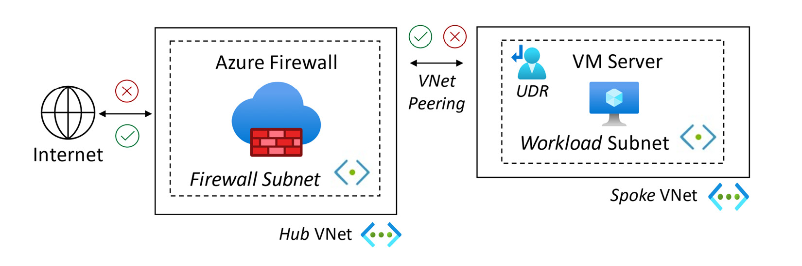
Figure 2.86 – Azure Firewall deployment topology
We created UDRs through a route table, associated it with the workload subnet, and created a new route to direct traffic with a destination of 0.0.0.0/0 to Azure Firewall as the next hop.
As part of the recipe for configuring Azure Firewall, we created a DNAT rule that allowed RDP access to our test virtual machine. We created outbound application rules to block and allow specified URLs.
Azure Firewall is a fully stateful Microsoft-managed firewall and an Azure-hosted firewall-as-a-service platform solution. It provides Layers 3-7 centralized control policies and consumes threat-intelligence feeds directly from Microsoft’s cybersecurity platforms, providing real-time insights and protection.
Segmentation of networks can be used with hub-and-spoke network topologies. The traffic flow and control from the spoke networks are provided through UDRs.
Azure Firewall can provide the following capabilities:
- Intrusion Prevention System (IDS)
- Transport Layer Security (TLS) inspection
- Uniform Resource Locator (URL) filtering
- Source Network Address Translation (SNAT)
- Destination Network Address Translation (DNAT)
It is important to note that TLS inspection is only supported for outbound (North) and lateral (East/West) traffic, that is, an inspection of traffic from an internal Azure-hosted client to the internet and sent from within Azure and to/from on-premises.
Azure Firewall Manager provides centralized policy configuration and management for multiple Azure Firewall instances.
See also
Should you require further information, you can refer to the following Microsoft Learn articles:
- Azure Firewall documentation: https://learn.microsoft.com/en-us/azure/firewall
- Azure Firewall FAQ: https://learn.microsoft.com/en-us/azure/firewall/firewall-faq
- Hub-spoke network topology in Azure: https://learn.microsoft.com/en-us/azure/architecture/reference-architectures/hybrid-networking/hub-spoke
- Azure Firewall web categories: https://learn.microsoft.com/en-us/azure/firewall/web-categories
- FQDN tags overview: https://learn.microsoft.com/en-us/azure/firewall/fqdn-tags
Implementing Azure Web Application Firewall
As we continue with our defense-in-depth strategy, we should look at the different types of traffic on the network, their protocols, and their direction, such as inbound/outbound and lateral traffic flows; this can be referred to as north/south and east/west traffic.
We should evaluate the most appropriate defense mechanism based on our desired outcomes. If we allow any HTTP(s) protocols into our Azure networks, such as to allow access to web applications, we need to implement measures to protect against Layer 7 web protocol attacks, such as cross-site scripting and SQL injection.
This outcome can be achieved by implementing a Layer 7 Web Application Firewall (WAF), rather than a Layer 4 network firewall.
It is important to note that a traditional Layer 4 network firewall will not offer protection against these inbound Layer 7 attacks; an Intrusion Detection and Prevention System (IDPS) solution will also be ineffective in detecting attacks in encrypted traffic.
Regarding inspecting encrypted traffic, we saw in the previous section that Azure Firewall could provide TLS inspection; however, this only supports outbound (North) internet traffic and lateral (East/West) traffic that stays within the Azure network or traverses cross-premises. Inbound (South) TLS inspection needs a WAF.
In this section, we will look at a recipe to implement a WAF using the Azure Application Gateway service to protect exposed HTTP(s) web services from Layer 7 web protocol attacks.
Getting ready
This recipe requires the following:
- A device with a browser, such as Edge or Chrome, to access the Azure portal: https://portal.azure.com
- You should sign in with an account that has the Owner or Contributor role for the Azure subscription
- An Azure virtual machine; we will walk through creating this virtual machine as a getting ready task:
- This will be created without an NSG attached to its network interface or the virtual machine’s subnet
- This will not have a public IP address associated with its network interface
Please continue with the following getting ready task of creating a workload server virtual machine with IIS installed to act as our application server for testing access through the application gateway.
Getting ready task – creating a workload server virtual machine with IIS to test access
- In the search box in the Azure portal, type virtual machines and select Virtual machines from the listed Services results:

Figure 2.87 – Search for virtual machines

Figure 2.88 – Virtual machines screen
- From the Basics tab, under the Project details section, set the subscription as required.
- Select the resource group we will use to create the application gateway in this recipe:
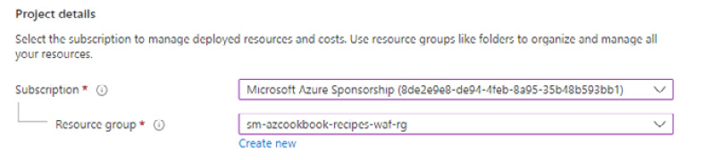
Figure 2.89 – Set project details
- Set the following:
- Virtual machine name: Type a name
- Region: Select a region
- Availability options: Select No infrastructure redundancy required
- Security type: Select Standard
- Image: Select Windows Server 2019 Datacenter - Gen2
- Size: Leave the default (or set it as required to reduce recipe costs)
- Set Username and Password as required:
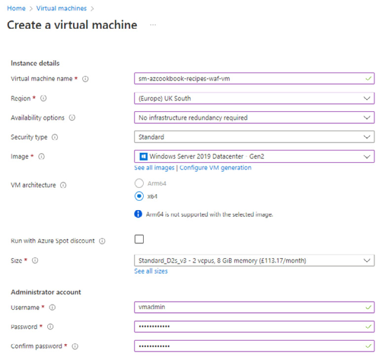
Figure 2.90 – Create a virtual machine
- Set Public inbound ports to None:

Figure 2.91 – Set inbound port rules
- Click Next : Disks, leave the defaults, then click Next : Networking.
- Select the virtual network we created earlier in this recipe when we created the application gateway.
- Select WorkloadSubnet for this virtual network:

Figure 2.92 – Configure the network interface
- Set Public IP to None.
- Set NIC network security group to None.
- Tick to enable Delete NIC when VM is deleted.
- Click Review + create.
- Click Create on the Review + create tab.
A notification will display that the resource deployment has succeeded:
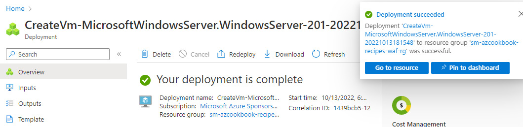
Figure 2.93 – Deployment completed
- To install IIS on the virtual machine, open Cloud Shell from the top navigation bar of the Azure portal:

Figure 2.94 – Launch Cloud Shell
- If this is the first time you have run Cloud Shell, you will be prompted to create a storage account; select your subscription, then click Create storage:
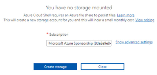
Figure 2.95 – Create Cloud Shell storage
- In Cloud Shell, select PowerShell:
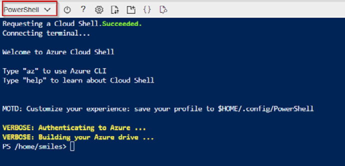
Figure 2.96 – Launch PowerShell
- Using your environment values for ResourceGroupName, VMName, and Location, run the following PowerShell command:
Set-AzVMExtension `
  -ResourceGroupName sm-azcookbook-recipes-waf-rg `
  -ExtensionName IIS `
  -VMName sm-azcookbook-recipes-waf-vm `
  -Publisher Microsoft.Compute `
  -ExtensionType CustomScriptExtension `
  -TypeHandlerVersion 1.4 `
  -SettingString '{"commandToExecute":"powershell Add-WindowsFeature Web-Server; powershell Add-Content -Path "C:\inetpub\wwwroot\Default.htm" -Value $($env:computername)"}' `
-Location WestEurope
The preceding code is represented in the following figure:
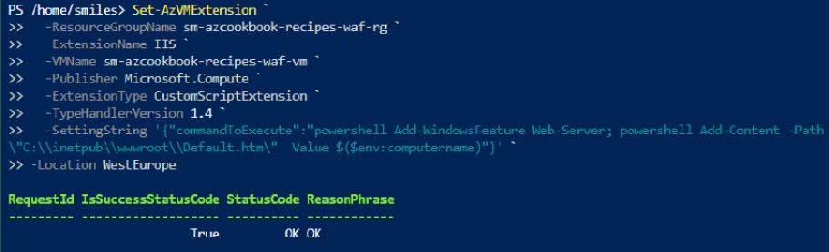
Figure 2.97 – Install web server feature
This getting ready task was for creating a workload server virtual machine with IIS installed to act as our application server for testing access through the application gateway.
You are now ready to continue to the main tasks for this recipe for implementing a WAF-enabled application gateway.
How to do it…
This recipe consists of the following tasks:
- Create an application gateway with WAF enabled.
- Add a server to the backend pool.
- Test the application gateway with WAF enabled.
- Clean up resources.
Task – creating an application gateway with WAF enabled
- In the search box in the Azure portal, type application gateway and select Application gateways from the listed Services results:

Figure 2.98 – Search for application gateway
- On the Application Gateway screen, click + Create or Create application gateway:
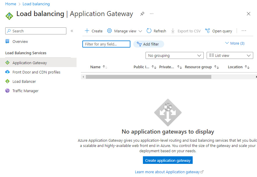
Figure 2.99 – Application Gateway screen
- From the Basics tab, under the Project details section, set Subscription as required.
- For Resource group, click Create new.
- Enter a name and click OK:

Figure 2.100 – Set project details
- Set the following information under the Instance details section:
- Application gateway name: Enter as required
- Region: Enter the same region selected for the workload virtual machine we created
- Tier: Select WAF V2
- Enable autoscaling: Leave the default
- Minimum instance count: Leave the default
- Maximum instance count: Leave the default
- Availability zone: Leave the default
- HTTP2: Leave the default
- WAF Policy: Click Create new; in the Create Web Application Firewall Policy blade, enter a name and select Add Bot Protection if required:

Figure 2.101 – Create application gateway
- In the Configure virtual network section, click Create new to create a new virtual network for this recipe.
- On the Create virtual network screen, enter a name.
- In the ADDRESS SPACE section, leave the default.
- In the SUBNETS section, set the following:
- Rename the default subnet to WAF-Subnet.
- In the second row of the table, type a subnet name of WorkloadSubnet, and for Address range, type 10.0.1.0/24. Click OK:
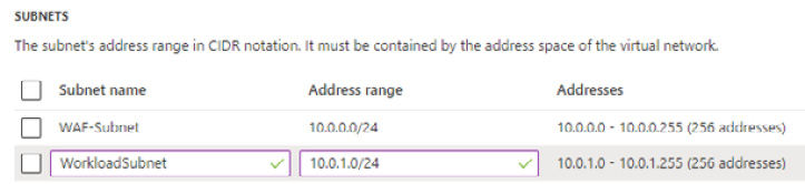
Figure 2.102 – Create a virtual network
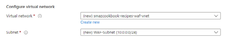
Figure 2.103 – Configure virtual network
- Click Next : Frontends.
- Ensure Frontend IP address type is set to Public.
- For Public IP address, click Add new.
- In Add a public IP, enter a name and click OK:
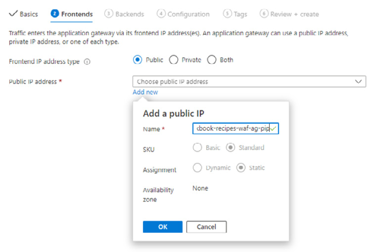
Figure 2.104 – Add a public IP
- Click Next : Backends.
- Click Add a backend pool.
- In Add a backend pool, enter a name, select Yes for Add backend pool without targets, and then click Add:

Figure 2.105 – Add a backend pool
- Click Next : Configuration.
- Click Add a routing rule under Routing rules:

Figure 2.106 – Add a routing rule
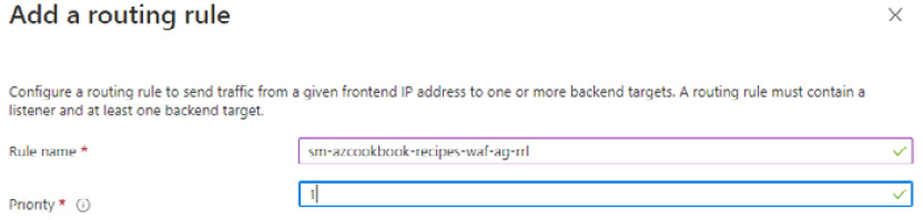
Figure 2.107 – Configure a routing rule
- In the Listener tab, set the following:
- Enter a name for Listener name
- Ensure Frontend IP is set to Public
- Ensure Protocol is set to HTTP
- Ensure Port is set to 80
- Ensure Listener type is set to Basic
- Ensure Error page url is set to No

Figure 2.108 – Configure routing rule listener
- In the Backend targets tab, ensure Backend pool is set for Target type; for Backend target, select the backend pool you created earlier in this recipe:
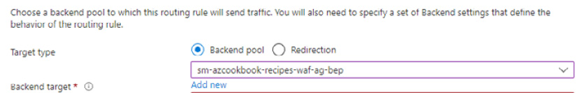
Figure 2.109 – Configure routing rule backend target
- For Backend settings, click Add new.
- In the Add Backend setting blade, enter a name for Backend settings name; leave all other settings at the defaults, and then click Add:
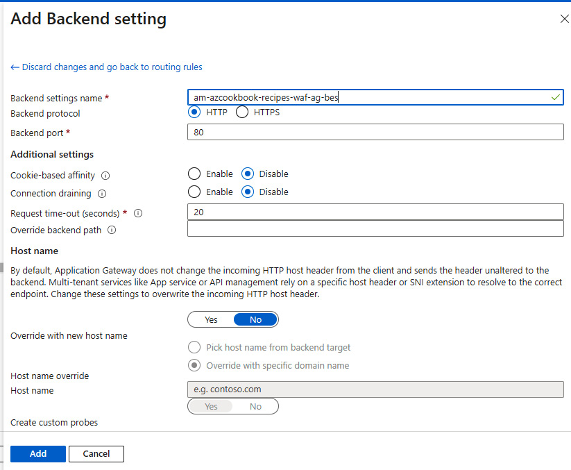
Figure 2.110 – Add routing rule backend setting
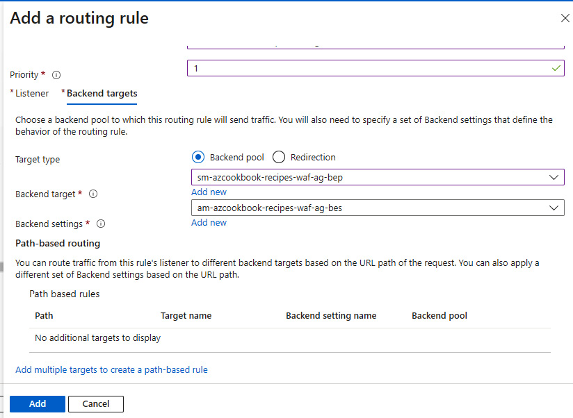
Figure 2.111 – Add a routing rule

Figure 2.112 – Configuration screen
- Enter any tags if required, then click Next : Review + create.
- Click Create on the Review + create tab:
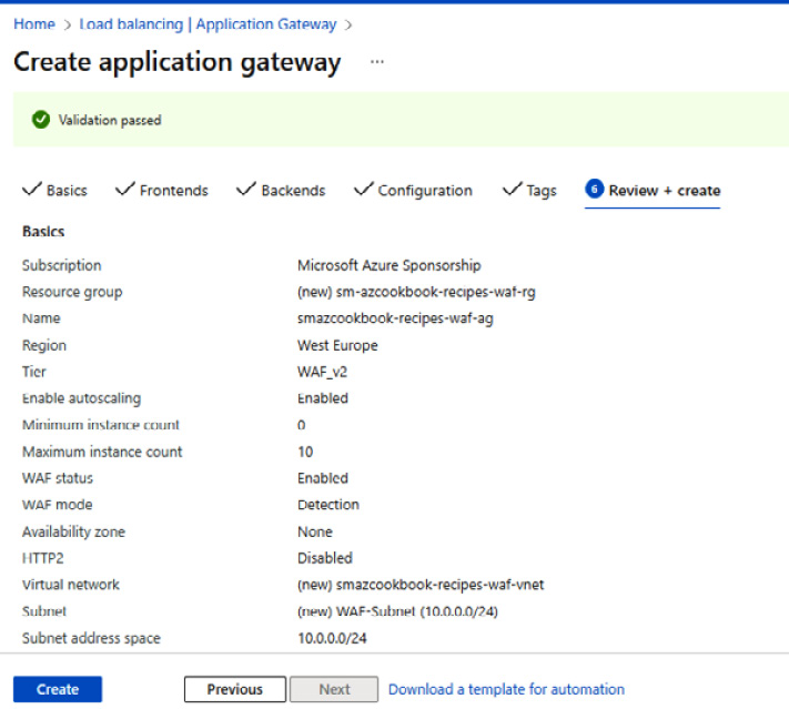
Figure 2.113 – Create application gateway
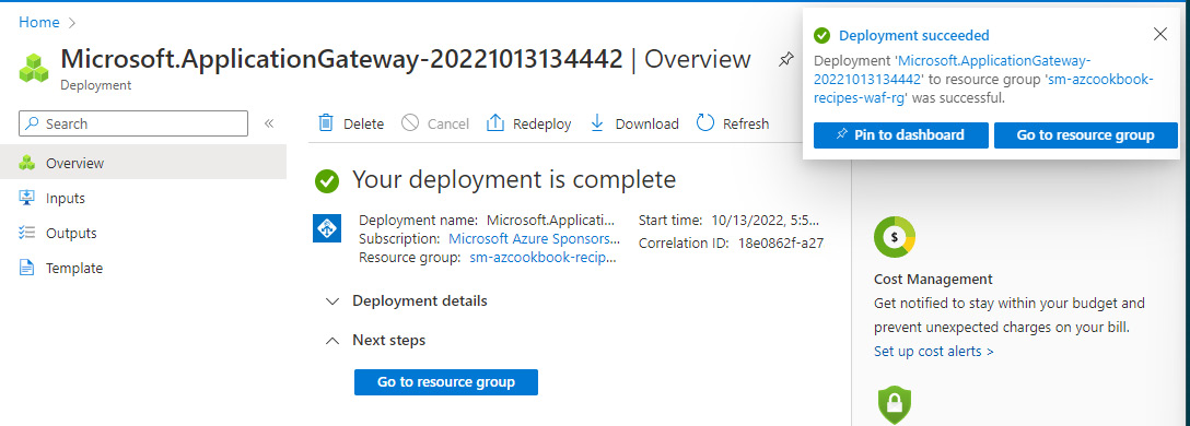
Figure 2.114 – Deployment succeeded
The task to create an application gateway with a WAF enabled is complete. We add our workload server to a backend pool in the next task.
Task – adding a server to the backend pool
- Navigate to your application gateway in the Azure portal, click on Backend pools under the Settings section, and click on your backend pool:

Figure 2.115 – Configuring application gateway
- From the Edit backend pool blade, under Backend targets, for Target type, select Virtual machine, and for Target, select the virtual machine we created as part of this recipe. Click Save:
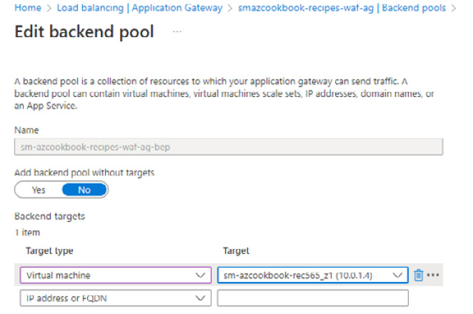
Figure 2.116 – Edit backend pool
- You will receive a notification that the deployment succeeded:

Figure 2.117 – Deployment succeeded
The task to create a workload server virtual machine with IIS installed is complete. In the next task, we test access to the web server through the WAF-enabled application gateway.
Task – testing the application gateway with WAF enabled
- From your application gateway, find your public IP address:

Figure 2.118 – Application gateway public IP address
- Copy and paste the public IP address into a browser, and ensure you receive a page served by your virtual machine using IIS. This confirms the successful configuration of the application gateway and your enabled WAF:
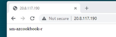
Figure 2.119 – Successful web server page access
The task to test access to the web application is complete. In the next task, we clean up the resources created in this recipe.
Task – cleaning up resources
- In the search box in the Azure portal, type resource groups and select Resource Groups from the listed Services results.
- On the Resource groups page, select the resource group we created for this recipe and click Delete resource group; this will delete all the resources created as part of this recipe.
The task to clean up the resources created in this recipe is complete.
How it works…
We looked at implementing a WAF as an integrated Azure Application Gateway service component in this recipe. We created a virtual machine with IIS installed as a workload server to test application access.
The WAF uses the Open Web Application Security Project (OWASP) ModSecurity (ModSec) core rule for application protection. This provides application protection against the OWASP Top 10 vulnerabilities, such as cross-site scripting and injection attacks; an injection attack example is SQL injection.
Further information can be found at the following URL: https://owasp.org/www-project-modsecurity-core-rule-set.
The Azure WAF deployment topology, when enabled as a component of the Azure Application Gateway service, is represented in the following diagram:

Figure 2.120 – Azure WAF deployment topology
There’s more…
WAF protection can also be implemented using the Azure Front Door service to provide centralized cross-region protection for your web applications from vulnerabilities.
We can also protect web application resources in other cloud environments or on-premises networks using the WAF as the entry point to access these applications.
See also
Should you require further information, you can refer to the following Microsoft Learn articles:
- Azure Application Gateway documentation: https://learn.microsoft.com/en-us/azure/application-gateway
- Web Application Firewall documentation: https://learn.microsoft.com/en-us/azure/web-application-firewall
- Web Application Firewall (WAF) on Azure Front Door: https://learn.microsoft.com/en-us/azure/frontdoor/web-application-firewall
- Tutorial: Create a Web Application Firewall policy on Azure Front Door using the Azure portal: https://learn.microsoft.com/en-us/azure/web-application-firewall/afds/waf-front-door-create-portal
Implementing Azure DDoS
In the previous section on implementing a WAF-enabled application gateway, we looked at protecting our web applications that are vulnerable to Layer 7 inbound web protocol attacks.
We continue, in this section, with our defense-in-depth strategy and look at additional protection methods for the protection of the network.
We will look at protecting Layers 3 and 4 of our network against Distributed Denial of Service (DDoS) attacks using the Azure DDoS Protection Standard service.
This recipe will teach you how to implement an Azure DDoS protection plan to protect your Azure virtual network(s).
We will take you through creating a DDoS protection plan and enabling protection for new and existing virtual networks, and provide information on how you may perform validation testing using Microsoft-supported third-party tools.
Getting ready
This recipe requires the following:
- A device with a browser, such as Edge or Chrome, to access the Azure portal: https://portal.azure.com
- You should sign in with an account that has the Owner or Contributor role for the Azure subscription
Pricing caution!
You should be aware that the DDoS Protection service has a fixed monthly price.
You will be charged the monthly fee regardless of usage if the service is active for the whole month. However, you will be prorated if only used for a portion of the month.
This is important to consider for this recipe as the service is $2,944 for an active month at the time of writing. We have included steps for removing this resource so that you do not receive a bill for longer than it was active in your environment.
Author disclaimer: It is strongly recommended that you do not leave this service running for any longer than required to implement and test this service as part of this recipe in a testing and evaluation scenario, due to the cost implications.
Further information on pricing can be found at this URL: https://azure.microsoft.com/en-gb/pricing/details/ddos-protection.
How to do it…
This recipe consists of the following tasks:
- Create a DDoS protection plan.
- Enable DDoS protection for a new virtual network.
- Enable DDoS protection for an existing virtual network.
- View protected resources.
- Clean up resources.
Task – creating a DDoS protection plan
Perform the following steps:
- From the top left of the Azure portal, click Create a resource:
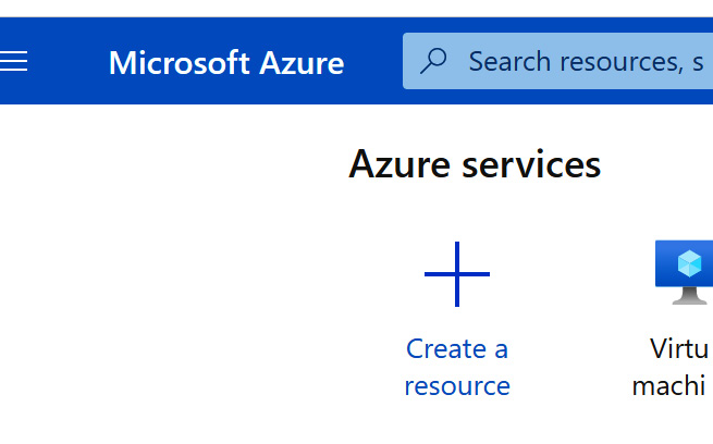
Figure 2.121 – Create a resource
- Type DDoS in the search box and select DDoS protection plan from the results:

Figure 2.122 – Search for DDoS
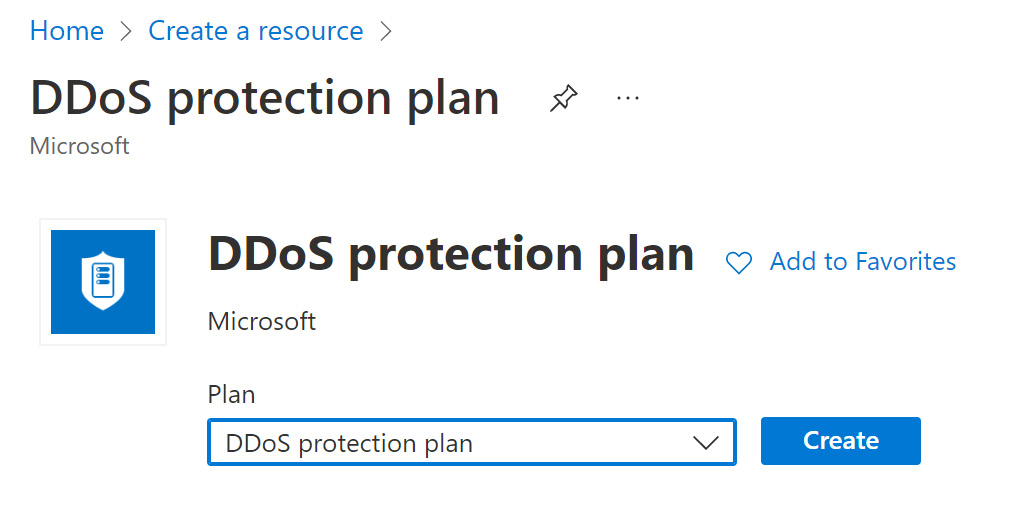
Figure 2.123 – Create a DDoS protection plan
- From the Basics tab, under the Project details section, set Subscription as required:

Figure 2.124 – Set Subscription
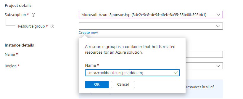
Figure 2.125 – Create a resource group
- Type in a name and select a region as required:
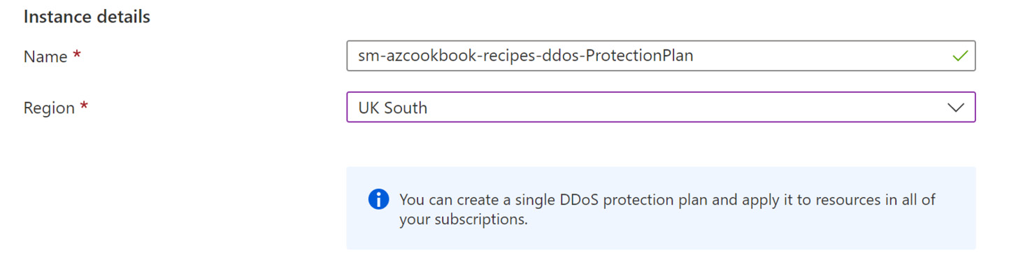
Figure 2.126 – Set instance details
- Click Review + create.
- Review the important pricing information and then click Create:
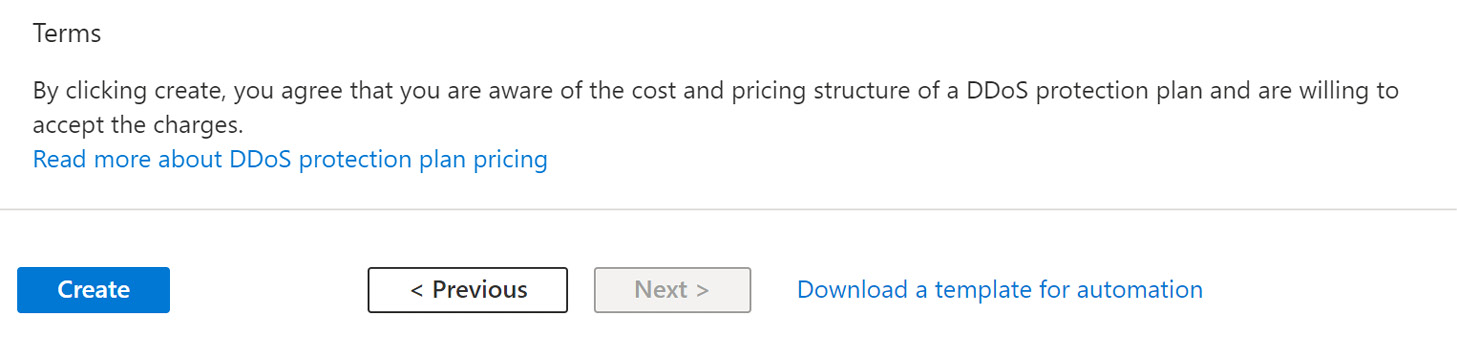
Figure 2.127 – Create a plan
The task to create a DDoS protection plan is complete. We will enable DDoS protection for a new virtual network in the next task.
Task – enabling DDoS protection for a new virtual network
- In the search box in the Azure portal, type virtual network and select Virtual networks from the listed Services results:
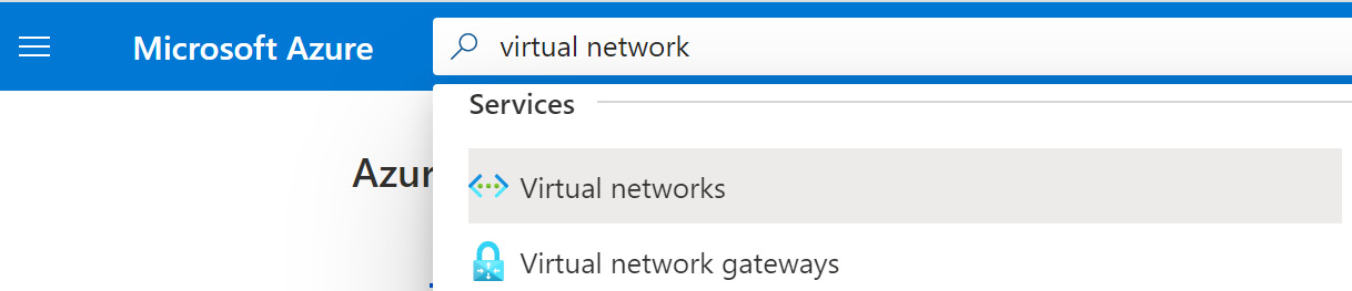
Figure 2.128 – Search for virtual networks
- On the Virtual networks screen, click + Create:

Figure 2.129 – Create a virtual network
- From the Basics tab, set Subscription and Resource group to the same values we set in the previous task in this recipe to create the virtual machine.
- Type a name and region as required, then click Next : IP Addresses.
- Leave the settings as the default on the IP Addresses tab and click Next : Security.
- From the Security tab, click Enable, and also read the information pop-up screen by hovering the mouse over the i information symbol:

Figure 2.130 – Enable protection plan
- Select the DDoS protection plan you created in the previous task:
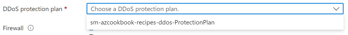
Figure 2.131 – Select the protection plan
- Click Review + create, then click Create once the validation has passed.
The task to set DDoS protection for a new virtual network is complete. In the next task, we enable DDoS protection for an existing virtual network.
Task – enabling DDoS protection for an existing virtual network
- If you do not have an existing virtual network without DDoS protection enabled, create a new virtual network to use this recipe as a getting ready task.
- Within the Azure portal, navigate to an existing virtual network on which you wish to enable DDoS protection.
- On the Virtual network screen, select DDoS protection under the Settings section.
- In the DDoS protection blade for the virtual network, select Enable and select the DDoS protection plan to use for this virtual network, then click Save

Figure 2.132 – Enable a DDoS protection plan
The task to enable DDoS protection for an existing virtual network is complete. In the next task, we view the protected resources in the DDoS protection plan.
Task – view protected resources
- Navigate to the DDoS protection plans screen; you can use the search box or select All services and filter to locate DDoS protection plans:
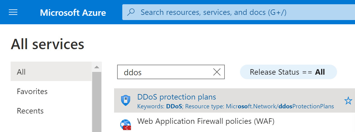
Figure 2.133 – Search for DDoS protection plans
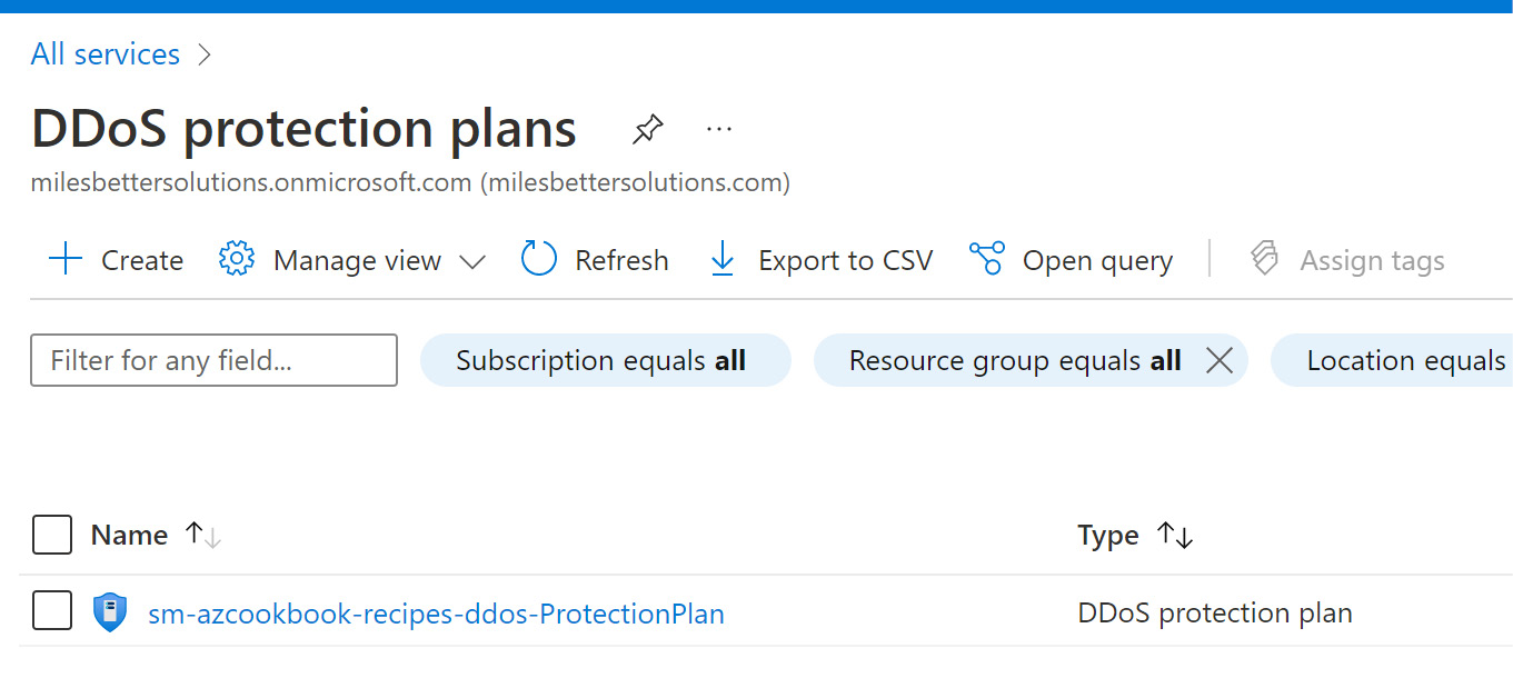
Figure 2.134 – DDoS protection plan
- Click on Protected resources under the Settings section, and you will see the virtual networks that we enabled to be protected.
The task to view the protected resources in our protection plan is complete. In the next task, we clean up the resources created in this recipe.
Task – cleaning up resources
Perform the following steps:
- In the search box in the Azure portal, type resource groups and select Resource Groups from the listed Services results.
- On the Resource groups page, select the resource group we created for this recipe and click Delete resource group; this will delete all the resources created as part of this recipe.
The task to clean up the resources created in this recipe is complete.
How it works…
In this recipe, we looked at implementing Azure DDoS Protection using the DDoS Protection Standard SKU and linking it to a virtual network.
A DDoS protection plan is created when DDoS Protection Standard is enabled. To get full protection, you can link virtual networks from multiple subscriptions of the same Azure AD tenant.
Azure as a platform has inherent DDoS network protection; however, this is there to protect at the infrastructure level, not at the individual customer-workload level.
By implementing this protection using the cost-based DDoS Protection Standard SKU at your specific workload layer, you can ensure targeted protection that is tuned to your web application traffic patterns. This provides much tighter protection than the generic volumetric infrastructure-level protection.
The following table shows a features comparison between the Azure platform-provided no-cost DDoS infrastructure protection and the cost-based DDOS Protection Standard:
|
Feature |
DDoS Infrastructure Protection |
DDoS Protection Standard SKU |
|
Automatic attack mitigation |
Yes |
Yes |
|
Active traffic monitoring and always-on detection |
Yes |
Yes |
|
Application-based mitigation policies |
No |
Yes |
|
Availability guarantee |
No |
Yes |
|
Cost protection |
No |
Yes |
|
DDoS rapid response support |
No |
Yes |
|
Metrics and alerts |
No |
Yes |
|
Mitigation flow logs |
No |
Yes |
|
Mitigation policy customizations |
No |
Yes |
|
Mitigation reports |
No |
Yes |
Table 2.1 – Azure DDoS Protection capabilities comparison
The public IPs will be protected when associated with virtual machines (including Network Virtual Appliances (NVAs)), load balancers, application gateways, Azure Firewall, Azure Bastion, and VPN gateways. Customers’ own custom IP prefixes brought into Azure are also protected.
The DDoS Standard Protection service can mitigate the following types of attacks:
- Volumetric attacks
- Protocol attacks (Layers 3 and 4)
- Resource-layer attacks (Layer 7)

Figure 2.135 – Azure DDoS Protection
There’s more…
It is important to note that should you wish to validate that the DDoS service will protect your resources from a DDoS attack, Microsoft will only allow the simulation of attacks using the following penetration testing partners:
- BreakingPoint Cloud: https://www.keysight.com/us/en/products/network-security/breakingpoint-cloud
- Red Button: https://www.red-button.net
See also
Should you require further information, you can refer to the following Microsoft Learn articles:
- Azure DDoS Protection documentation: https://learn.microsoft.com/en-us/azure/ddos-protection
- Azure DDoS Protection reference architectures: https://learn.microsoft.com/en-us/azure/ddos-protection/ddos-protection-reference-architectures