
In This Chapter
With the introduction of the Java 2 Platform, Enterprise Edition (J2EE), Java has evolved into the language of choice for Web and component-based enterprise development endeavors. The sheer volume of technology offered by J2EE is exciting and at the same time staggering in its scope and applicability. However, it is important for you to recognize that J2EE is purely an application development specification consisting of technology components and services, and Java is its implementation language. For this reason, the success you derive from constructing and deploying your J2EE-based applications is governed by your software design process—visually communicating requirements, initiating the optimal analysis and design decisions, and recognizing the best implementation choices.
This chapter’s objective is to provide a very clear roadmap showing how you can leverage the Unified Modeling Language (UML) to develop a software design and realize the design as an enterprise Java application using the J2EE specification and associated J2EE industry best practices. In Chapter 3, “A Developer’s Guide to the Unified Modeling Language (UML),” the features and structure of the UML diagrams and artifacts were presented. In this chapter you will apply that knowledge to create a model of an enterprise application that uses J2EE components and services.
I couldn’t wait for success...so I went ahead without it.
—Jonathon Winters
J2EE software design is an extremely coordinated and disciplined process that needs to occur well before any line of Java code is written. The objective is to create a visually clear blueprint (model) for the entire application so your business requirements semantically map to J2EE technology components and services in the most efficient, performance-oriented, scalable, and maintainable manner.
The effort that is put into the software design of J2EE applications, however, is slowly diminishing, not to the point of extinction, but to a point where the project can be at risk for not delivering the necessary levels of integrity, extensibility, and maintainability the business requires to have a reason to let the application evolve. Clearly, long before application deployment, these risks must be identified and understood to ensure that the correct solution is created. As covered in Chapter 3, the time to identify technological risks is during the project inception or the analysis of the requirements when the Use Cases are being defined.
Several influences within a project contribute to the lack of software design; you should immediately recognize and address influences such as
A general lack of J2EE software design experience within a project team.
Every project must have on board a technology architect and Java developers who understand what software design involves through experience. For instance, they must understand how to leverage the J2EE specification, component design patterns, and associated best practices of developing solutions targeted for a specific application infrastructure, such as the WebLogic Platform.
A lack of communication among the design team has wide-ranging negative ramifications.
Software design is a team effort in which all members of the development team should have input and a consensus understanding on the construction and deployment of the J2EE application. In a situation in which the design is articulated in a non-teamwork fashion, there is a risk that developers will not totally understand the rationale for some of the design decisions and, hence, may defer design flaws to a later point in time.
J2EE projects are, by nature, more focused on binary deliverables that can be showcased as quickly as possible to the end users and sponsors to show progress.
J2EE software design is not application development; it is a process that leads to the software engineering effort of an application that is compliant with the J2EE specification and associated best practices. In time-crunched and showcase-based projects, the software design process is typically replaced or bypassed with a development trial-and-error process, which eventually evolves into the software design of an application. In such an approach, thought is replaced with haste and the consequences lead to a fragmented approach to constructing the software that requires more effort and time to get right. Software design should be a process in which an application’s design evolves through refinement, not through complete redesign.
Like any process, software design is only as good as the input it receives and the formula applied to it to develop the output (application design).
The Unified Modeling Language (UML) has achieved de facto status as the notation used by architects and developers to visually represent the classes, objects, messages, and interactions in an object-oriented system. The value of adopting this notation in your development shop is best described by the infamous saying “...a picture is worth a thousand words.” A UML diagram is worth an exponentially larger number of words in terms of its capability to easily and effectively describe, in visual terms, the way a system works and how all the pieces fit together.
Another value is that, like Java, UML is language and platform neutral. However, it is possible to extract more value from UML because it provides the ability to stereotype and implement language-specific behaviors such as Enterprise Java Beans (EJBs) when you know the target will be a J2EE application.
The J2EE transition actually occurs very early in the software development process; for example, the relationships between Actors and Use Cases identify the required boundary interfaces. Identifying the boundary interfaces provides very significant information for selecting design patterns, which are discussed in the next section.
Using the UML diagrams and artifacts as your input, you can perform the following:
Evaluate the design to choose candidate technologies.
Evaluate the design to identify design patterns.
Create the user interface.
Create the Boundary and Support classes.
Several key items in a UML design model identify an enterprise solution. These items are found in the Use Cases, Activity diagrams, Class diagrams, and Deployment diagrams. In Class diagrams, the user and system interfaces are referred to as Boundary classes. You can check whether your Boundary classes evaluate to a J2EE solution by identifying the need for any of the following items:
Web browser user interface
Thin client
Persistence
Multi-tiered distributed system
Multiple clients
The design may be geared toward a particular technology. If the design model references a technology, such as an EJB, your job to choose a technology will certainly be much easier. If, on the other hand, it does not, you will have to evaluate the design model and research existing technologies to discover a match. The worst case scenario may lead you to writing a lot of code from scratch.
Before writing lines of code, it is important to draw from the experience of others. There are some programming techniques that are reused so often, they have been given the name Design Patterns. In general, Design Patterns are reusable design solutions to common problem scenarios that occur during the development phase of an application. Design Patterns not only provide a consistent real-world design approach that developers can leverage to resolve development issues, but they also provide the capability to instill flexibility, scalability, and manageability into the application’s design.
Even if you are not familiar with the term Design Patterns, there is a possibility that you have been incorporating patterns in your code. For example, certain Java Foundation Classes (JFC), also known as Swing, use the Model-View-Controller (MVC) design pattern, where:
Model represents the business logic and data associated with an application.
View represents the presentation data.
Controller represents the decision making component of an application.
For example, in a Swing GUI that displays a table of data, the JTable provides the view, the TableModel provides the model, and your application provides the control.
Like many object-oriented techniques, the MVC architecture originated in the Smalltalk programming language. The fundamental idea behind MVC is to minimize the coupling between objects by aligning them with a specific set of responsibilities. In this case, the responsibilities are maintaining state and persistent data (Model), rendering the data for presentation (View), and executing application logic (Control). Figure 6.1 illustrates the MVC architecture.
Figure 6.1. The objects in a Model-View-Controller architecture have a specific set of responsibilities.
As illustrated in Figure 6.1, the View sends Queries to the Model to get the data that it will render and display. The View also sends User Events to the Controller, causing the controller to perform workflow and application logic on behalf of the user. The Controller sends model changes to the Model to notify which persistent data must be made available for viewing. The Model, in response, notifies the View of these changes through a change notification message, causing the View to update the displayed data.
The Model-View-Controller pattern is arguably the most fundamental design pattern behind J2EE itself; it provides a clear separation of system duties into distinct domains that are prevalent in almost every J2EE distributed system. For example, implementing a basic J2EE application architecture based on MVC would be represented as illustrated in Figure 6.2, where:

JavaServer Pages fall into the View (presentation) domain.
Servlets fall in the Control (data/flow orchestration) domain.
Enterprise JavaBeans (Entity beans) fall in the Model (data) domain.
Being such a significant influence on the J2EE architecture, it is very important that J2EE application developers have a firm understanding of the Model-View-Controller architecture.
Note
The J2EE Application Programming Model is based upon the MVC design pattern, as discussed in Chapter 5, “The J2EE Architecture and APIs.”
One of the most difficult steps in starting a new project is identifying the system boundaries and the interaction between the components. When designing an enterprise J2EE application, it is extremely helpful to leverage the MVC design pattern to ensure the system boundaries and interaction between the components is established and well defined.
Note
Each component of an enterprise J2EE application typically falls into one of the three domains: Model, View, or Control.
The MVC architecture can also be modeled using the UML Activity Diagram. This is a very powerful mechanism to visualize and communicate the flow sequence of the J2EE application.
The mapping of a use case flow of events to an activity diagram involves applying swimlanes to the activity diagram to identify which component is performing the activity. For this reason, we can label the swimlanes View, Controller, and Model. There are a variety of requirement scenarios that dictate what J2EE components will be used towards the design of an application. A very typical J2EE application has a servlet that formats the data for viewing, Session beans to perform the workflow, and entity beans to represent the persistent data. As a UML activity diagram, this typical J2EE application can be modeled in a UML Activity diagram as shown in Figure 6.3.
A complete Activity diagram used in the analysis of an enterprise application is provided in the Truck Rental case study later in this chapter.
These Design Patterns were originally organized by the “Gang of Four” hence, the reason why they are commonly known as “GoF” patterns in the development community. The term “Gang of Four” refers to the four authors of the book Design Patterns: Elements of Reusable Object-Oriented Software: Erich Gamma, Richard Helm, Ralph Johnson, and John Vlissides. These Design Patterns are organized into the following three major pattern categories:
Creational, which are concerned with the way instances of an object are created.
Structural, which focus on the associations between objects.
Behavioral, which concentrate on the communication between objects.
It is very likely that you can use many of these patterns to help design your Class Diagrams and Interaction Diagrams. For example, the UML Sequence Diagram models the interaction between objects. From the sequence diagrams, Behavioral Design Patterns can be identified which define the communication between objects.
It is highly recommended that you become familiar with Design Patterns. Your entire software development process will become much more efficient. A classification summary of the GoF Design Patterns is represented in Table 6.1.
Table 6.1. A Classification Summary of GoF Design Patterns
Factory Method | Defines an interface for creating an object |
Abstract Factory | Provides an interface for creating families of related or dependent objects without specifying their concrete class |
Builder Pattern | Separates the construction of a complex object from its representation |
Prototype Pattern | Specifies the kinds of objects to create using a prototypical instance |
Singleton Pattern | Ensures a class only has one instance |
The components of the J2EE architecture make extensive use of design patterns. Specific examples of how design patterns are used with EJBs are covered in the next section.
Becoming familiar with the capabilities of J2EE technology is important so that you can begin visualizing a J2EE solution early in your design. For example, by having a firm understanding of EJBs, you can design class diagrams with this technology component in mind. Hence, the overall software development process will be more rapid, and round-trip engineering can be achieved because the design and code are more tightly coupled. Though several excellent software development tools are on the market, the authors of this book have had a great deal of real-life success with the Together ControlCenter product. This tool has very strong built-in support for EJB software development, object-oriented analysis, and seamless WebLogic interoperability.
Note
For more information on the Together ControlCenter product, please visit the Borland Web site, www.borland.com, which recently acquired TogetherSoft.
Enterprise applications provide many improvements on the traditional client/server model. Whereas a client/server application has two logical tiers, the client and the server, a J2EE application has four logical tiers. It is vital that you understand that these tiers are logical and, hence, location transparent. It is possible to have a simple architecture in which all four tiers are physically located on one machine, in which all four tiers are physically separated, or in any other combination. This architecture provides you an unprecedented level of control over the proximity of components to one another, allowing for optimization of system resources for performance or business requirements. Table 6.2 lists the four logical tiers.
The tiers identify the components that must be designed, the interfaces between the components, and the overall deployment model of the J2EE application. As the Model-View-Controller design pattern dictates, the JSP is the View because it renders the data into the format that will be viewed by the client tier, the entity EJBs are the Model, and the servlets or Session beans are the control. In general, there is a JSP that interfaces with a servlet, which, in turn, is a client to a Session bean. Session beans delegate the persistence requirements to the entity beans, which, in turn, delegate the database calls through JDBC to a database server. The business logic is performed by the Session bean.
Because J2EE provides most of the enterprise framework, the major portion of the original design work therefore is focused on the EJBs themselves. The three major classes of Enterprise Java Beans are the entity bean, session bean, and message-driven beans. Each bean type has unique a characteristic and behavior, which allows them to solve a whole host of distributed application scenarios, as shown in Table 6.3.
Throughout the analysis and design, you should attempt to identify design patterns. EJBs provide the solution for a number of design patterns, for example:
Note
For more information on design patterns, we strongly recommend the book Design Patterns: Elements of Reusable Object-Oriented Software (Gamma, et al). Published by Addison Wesley Longman, Inc. ISBN 0-201-63361-1.
Proxy pattern—. Both entity and session beans use remote interfaces as a proxy to the business logic object that is more expensive to create.
Factory pattern—. The factory interface that is used to create an instance of the remote interface follows the factory pattern.
Mediator pattern—. A session bean is often used to centralize control over a group of entity beans.
Façade pattern—. When a single session bean is used as a simple front-end to a group of entity beans, the session bean is a façade. This layering approach provides a single unified interface to the client to the more complex subsystem.
When your analysis identifies the need for EJB functionality, you will create class diagrams using EJB classes. The Together ControlCenter provides a Class By Pattern tool; when this tool is used to add classes to the class diagram, a Choose Pattern dialog is automatically opened. The EJB Pattern includes the subtypes: Entity EJB, MessageDriven EJB, and Session EJB, as shown in Figure 6.4.

Figure 6.4. The Together ControlCenter provides tools to add classes by pattern to the class diagram including EJB patterns.
Each of the patterns has properties that you can access by right-clicking on the class after it has been added to the diagram. As shown in Figure 6.5, the Session EJB includes a property to choose stateful versus stateless. This affects the code that is automatically generated by Together.

A stateless session bean is the simplest type of EJB. The bean does not maintain any state information between method calls. Each method call is like talking to a new instance of the object. The benefit of implementing this type of bean is that memory use is not nearly as impactful as with stateful EJBs because no state is maintained between invocations on behalf of the caller.
In a WebLogic cluster, stateless beans generally scale better because invocations can be routed to any instance, whereas stateful invocations must maintain primary server affinity and state information is replicated to a secondary server for high availability. There is some overhead to this affinity and replication; however, in some cases the high availability and scalable solution can often outweigh the resource cost.
A stateful session bean maintains state for the client between invocations of methods. This ties the client to a specific instance of the session EJB. Stateful session beans are therefore not reusable as stateless session beans. The caching and pooling of a stateful session bean is performed by the EJB container using the ejbActivate() and ejbPassivate() methods, respectively.
Entity EJBs are added to the class diagram in Together ControlCenter using the Class by Pattern tool. The properties for the entity EJB include a selection for Bean Managed or Container Managed Persistence, as shown in Figure 6.6.

Figure 6.6. Selecting the property type of an Entity EJB using the Together ControlCenter—Bean or Container Managed persistence.
In Container Managed Persistence (CMP), the attributes of the entity bean are persisted, usually to a relational database, by the EJB container. Attributes in the deployment descriptor provide the mapping between the bean and the relational database. The deployment descriptor is an XML document that describes the location, persistence, and security of the bean. The advantage of CMP is that it makes the bean much easier to implement and also more portable because it uses declarative mapping instead of hard-coded JDBC database access.
In Bean Managed Persistence (BMP), the persistence is implemented by the Enterprise Bean provider. As such, the developer writes the code to interact with the database or other persistent storage to create, update, and delete the data referenced by the entity bean. The advantage of BMP is that it gives you complete flexibility and control of the persistence; however, you should use it only if CMP lacks the capability that you require because you are, in essence, hard-wiring the access, which can limit the bean’s portability and reusability.
Every entity bean has a corresponding home interface that controls its life cycle. It provides the methods to create, locate, and remove the entity bean. The usage of the home interface will be evident in the sequence diagram, which shows when the client creates and destroys the bean.
This interface also exposes the remotely accessible methods. When Together ControlCenter is used to design the Java Enterprise Application, the home and remote interfaces are encapsulated by the class that provides the client-link to the Enterprise Java Bean. The client-link is selected from the EJB Clients pattern from the Class By Pattern tool.
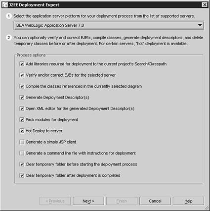
An enterprise J2EE application is deployed as an Enterprise Archive (EAR) file, which can contain one or more of each of the two other archive file types: the Web Archive (WAR) and the Java Archive (JAR) files. The WAR contains the servlet classes, images, JSPs, HTML, and other resources. The JAR contains the EJBs and other supporting compiled Java classes. The Together ControlCenter provides the complete platform to Model-Build-Deploy J2EE applications. The J2EE Deployment Expert menu item fully supports deployment for the WebLogic 7.0 application server platform, as shown in Figure 6.7.
This section presents a sample design model of an application, which will allow you to gain exposure to the process of mapping UML artifacts to a J2EE application architecture. The example showcased will be focused on the administration and customer support for a truck rental business, which will require developing the following UML artifacts:
Use cases
Activity diagrams
Class diagrams
Sequence diagrams
Deployment and component diagrams
The first step is to consolidate the requirements that are focused on the types of rental queries that a customer may make and the administration of those requests, as follows:
Customer requires a particular type of vehicle, i.e. truck or van.
Customer requests a capacity, i.e. number of passengers, payload.
Customer requests a price range.
Customer requests number of days for rental.
Customer searches for vehicle meeting requirements.
Administrator updates persistent data to maintain inventory of vehicles.
Administrator views status of requests, i.e. success or no matching vehicles.
These requirements indicate the need for a user interface that is easily accessible by multiple clients. There is also a need to maintain persistent data.
You can visualize the analysis of the requirements through use case diagrams. The process of creating use case diagrams helps you analyze the requirements and gain a deeper understanding of the problem domain. As you gain this understanding, you can refine the use case to better describe the results of the analysis.
The process is fairly straightforward. First, you choose actors to represent system roles that users play and choose the use cases, or system interactions, that they will perform. Second, you review the use cases to make sure that the scenarios adequately portray the requirements. In the diagram, the actor with its use case should sound like a simple sentence, such as “Customer specifies type of vehicle required” or “Customer searches for vehicle matching requirements,” as illustrated in Figure 6.8.
As you refine the use cases, you can identify Generalizations, Include, or Extension relationships.
Note
▸ To learn about applying Generalizations, Include, or Extension relationships in Use Cases, see “The Features of a Use Case Diagram,” p. 102.
The following sections will elaborate the use cases shown in Figure 6.8.
The Edit Request use case is performed by the Customer actor, as follows:
Customer fills out form specifying request criteria.
Update the form to include the new field if it is a common request.
An alternative flow occurs if the form does not include an entry for a request of the customer.
The Search for Vehicle use case is also performed by the customer, as follows:
However, a prerequisite is that Use Case 1 has already been performed by the same customer.
The alternative flow for this use case occurs if no matches are found, hence the request form will be stored in a list of failed searches. The Administrator will view the failed searches to determine if the inventory of available vehicles needs to updated for a particular type of vehicle. The alternative flow is therefore to have the Administrator perform the View Search Results use case.
The View Search Results is performed by the Administrator. The purpose is to determine if the inventory matches the customer requests, as follows:
Administrator specifies search criteria for search results to match.
All matching results are presented to the Administrator.
Administrator evaluates list against inventory.
The Update Inventory use case is also performed by the Administrator, as follows:
Administrator determines types of vehicles that always fail the search.
Administrator determines types of vehicles that are never requested.
However, a prerequisite is that Use Case 3 has already been performed. There are no alternative flows for this use case.
To gain further understanding of the Truck Rental use cases, you may find it useful to create an activity diagram. This diagram helps identify the activities that are performed in each use case. Also, since the prevalent design pattern for enterprise J2EE applications is the Model-View-Controller pattern, it is very valuable to initially map the Truck Rental use cases to activity diagrams with MVC swimlanes, as illustrated in Figure 6.9, which will assist you in identifying what J2EE components could potentially be targeted for implementing those activities.

The Together ControlCenter Model-Build-Deploy platform is the perfect tool for creating the EJB class diagrams, since its class diagram design tool contains templates for creating entity, session, and message-driven EJBs.
As illustrated in Figure 6.10, the View domain is designed as a servlet, the Control is designed as session EJBs, and the Model is designed as entity EJBs. The design for the user interface will be an HTML form with the servlet to service the request. The servlet will encapsulate a client-link to a session EJB, which will perform the application business logic. The session EJB will in turn use an entity EJB to maintain persistent storage of inventory and logged status information.
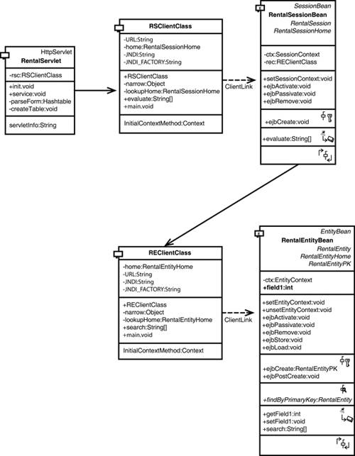
The Together ControlCenter can automatically generate Sequence and Collaboration diagrams from methods in the class diagram. The method that has particularly interesting interaction behavior in this design model is the service() method in the RentalServlet. From the sequence diagram in Figure 6.11 and collaboration diagram in Figure 6.12, you can see that the Enterprise Java Beans are dynamically created when the client requests their services.
At this point, from the analysis of the requirements, the initial design has been created. After reviewing the design to ensure that it addresses all the requirements, you can now focus on coding the application in Java. The Together ControlCenter generates source code for each class that appears in a class diagram. The design for the Truck Rental example generated the following 10 classes:
RentalServletRSClientClassRentalSessionRentalSessionBeanRentalSessionHomeREClientClassRentalEntityRentalEntityBeanRentalEntityHomeRentalEntityPK
The RentalEntity and RentalSession are the remote interfaces. RentalEntityHome and RentalSessionHome are the home interfaces. RentalEntityPK is the primary key for the entity bean. You should not manually edit any of these support files if they were generated by the Together ControlCenter.
The REClientClass and RSClientClass encapsulate the Home and Remote interfaces for the corresponding RemoteEntity and RemoteSession respectively. These client links are the proxy for the bean. You will add operations to the client classes to forward the message to the bean.
As you create the class diagrams with Together ControlCenter, it dynamically generates Java source code. The final transition to J2EE is to edit the generated source files, where indicated with comments and add the necessary import statements.
You have now taken a problem domain and mapped it to UML diagrams that communicate the system to other analysts and architects. The first diagram created, the use case diagram, formed the basis of the rest of the analysis. In real-life enterprise systems, this process can take several iterations and often involves sequence, state, and activity diagrams. More than just pretty pictures, these diagrams were effortlessly forward-engineered into J2EE code by the Together ControlCenter tool.