With the needs of the business world becoming entangled in a web of complexities such as conflicting requirements, potential miscommunication, and technological risks, it is imperative for software development teams to adopt a technique that can effectively capture the real-world context for business requirements and problems (the problem domain), and then evolve them towards defining a software solution.
The value of using object-oriented analysis and design techniques for developing software derives from two facts; it enables the real world business complexity to be addressed in a very modular and disciplined manner, and promotes the development of software solutions that are inherently maintainable over time.
However, prerequisites exist for designing object-oriented software solutions. The first is fluent communication among everyone involved in creating and deploying the software solution—the more complex the solution, the more critical communication becomes. The second prerequisite is a unified language that describes concisely and without misinterpretations the software analysis and design tasks at hand that will ultimately dictate the solution system.
In the past, there were “Method Wars” where many formal object-oriented software development methodologies, each with its own proprietary language, battled to be the standard approach for capturing the analysis and design efforts of a project. This was a trying time for everyone involved in object-oriented development projects because there was no consistency in how software solutions were methodically analyzed, designed, and developed. The leading methodologists in this paradigm—Grady Booch, James Rumbaugh, and Ivar Jacobsen, also known as the “Three Amigos,” resolved this frustration by establishing the Unified Modeling Language, or UML, which today has emerged as the de facto software development blueprint language.
As a software developer, you will be challenged to create software solutions where the need for the solution initially surfaced as a problem to be solved. This chapter’s focus is to explain clearly how to use UML effectively in the Analysis and Design phases of a software development lifecycle.
The Unified Modeling Language (UML) is a graphical object-oriented modeling language that provides a visual syntax for capturing the important elements from a business problem domain and documenting it as a series of visually self-describing models, known as artifacts. A collection of artifacts pertaining to a specific business problem is known as the model domain.
UML does not describe or dictate how software should be developed. Instead, it promotes a process of abstraction where the essential elements and their respective attributes within the context of a business problem are separated from the whole business problem. This provides an extremely visually oriented and focused platform for deriving a software solution.
UML supports many types of artifacts, because there are many perspectives from which to observe a software system depending upon who you are in relation to the project. For example, a software developer will be interested in converting the design of the software into programming code, while a business analyst will be interested in the behavior of the software solution in relation to the initial problem domain. The UML artifacts are categorized by eight primary diagrams, as described in Table 3.1. Textual artifacts do exist in the context of these eight diagrams and will be discussed later in this chapter with their respective diagrams when applicable.
Table 3.1. A Description of the Eight Primary UML Diagrams
UML Diagram | Purpose |
|---|---|
Analysis Phase: Models the context and boundaries of a system or subsystem. | |
Analysis Phase: In conjunction with Use Cases, can provide a Conceptual model of a system. Design Phase: Models static structural aspects. | |
Design Phase: Models a series of messages exchanged by a selected set of objects with an emphasis on the chronological course of events. | |
Design Phase: Models a set of interactions between selected objects in a specific situation, focusing on the relations between the objects and their topography. | |
Design Phase: Models a sequence of states the objects of a class can assume during its lifetime, together with the events that cause changes of state. | |
Analysis and Design Phase: Models the procedural possibilities of a system with the aid of activities. | |
Design Phase: Models the interrelations between software components. | |
Each UML diagram in Table 3.1 models a specific aspect of a software system, and hence contributes to the overall abstraction process of a problem domain. For example:
The artifacts also exist as living documents that provide an ideal reference for software maintenance by providing all the traceable details of what the software was intended to do and how it intended to do it.
One of the definitions of discipline is the knowledge or training gained from misfortune or bad conduct. The objective of a software development methodology is to adopt and then promote a series of disciplines that, if followed in a methodical and disciplined manner, can lead to a successful software development process. There are a variety of methodologies that can be applied towards the development of object-oriented software, such as the Rational Unified Process (RUP), eXtreme Programming (XP), and Feature-Driven Design. These methodologies provide structure to help monitor a predictable schedule by assigning phases or steps to the development lifecycle.
Note
▸ To learn more about software development methodologies, see “Software Development Methodologies,” p. 51.
UML by design, is neither a methodology nor identified with any one particular software development methodology. No matter which methodology you decide to use, UML can be embraced as a standard modeling notation. The modeling notations provided by UML exclusively address the analysis and design phases of a software development lifecycle, where UML artifacts are used to record the analysis and design decisions. Through the visual representation of the analysis and design phases using UML, you can easily:
Consolidate the software system requirements to the core elements that will constitute the critical aspects of the solution system, which can streamline your development effort.
Identify risks visually.
Communicate the analysis and design in a common vocabulary via UML artifacts.
Maintain traceability between the analysis and design phases so you can verify the root of your design decisions.
Produce detailed and validated information regarding the logical and physical design of a software solution.
However, the approaches and activities undertaken in the analysis and design phases to derive UML artifacts are governed by which methodology you are using.
UML artifacts are primarily diagrams with supporting textual information. To efficiently generate these diagrams and manage their supporting information, it is extremely important to leverage an analysis and design modeling tool that supports the UML standard as specified by the Object Management Group (OMG). There are plenty of modeling tools, graphics packages, and Java Integrated Development Environments (IDEs) that do provide UML support.
However, the Together ControlCenter (TCC) 6.0 product from the TogetherSoft Corporation is the modeling and development product of choice within this book. The motivations for this decision are because TCC is the only product that successfully provides an intuitive end-to-end Model-Build-Deploy development platform for constructing J2EE enterprise solutions on the BEA WebLogic Platform 7.0. The TCC enables business analysts, application architects, and software developers to leverage a single modeling and development environment, minimizing the need to acquire, learn, and use multiple products.
Also, the TCC is the only development tool that works the way developers work. Because TogetherSoft understands that development is iterative, TCC provides features that encourage forward momentum throughout development, for example:
Simultaneous round-trip engineering makes code and model mismatch a thing of the past. Make changes to the model or the code and each stays in sync—no waiting, no extra steps. Plus, round-trip engineering provides visibility into existing applications, generating class models instantly.
Patterns eliminate tedious tasks and speed the development process. ControlCenter’s pattern repository includes industry-recognized J2EE patterns, UI patterns, test cases, and more. Using the template expert, developers can also customize and add to the offerings easily. Time-consuming tasks are taken care of with a few clicks and developers can move on to serious coding.
Refactoring improves code quality quickly, easily, and safely. ControlCenter’s extensive refactoring makes sure that all changes are correctly propagated throughout an application. Code does not break and quality is improved without a hassle.
Deployment to multiple J2EE servers is fast, with no re-coding required. Hence, applications can be built for one J2EE server and easily switched to another, protecting development assets even if server changes are required.
Quality assurance features take the pressure off development. Extensive audits and metrics spare developers from the headaches of searching code for errors. Built-in unit testing even helps uncover problems during the coding process.
Documentation generation is reliable and complete. Automatic documentation generation relieves developers from the time-consuming, tedious, but necessary step of documentation. With just a few keystrokes, standardized documentation is delivered on time, and the developer is free to build applications.
Another advantage that will be of primary importance to an enterprise is that the TCC product itself is not bound to any specific development methodology nor does it enforce any. This enables project teams to decide a methodology based on the type and scale of their project, rather than based on a modeling tool.
Note
You can find more information about the Together ControlCenter product from visiting the TogetherSoft Web site at www.TogetherSoft.com.
As previously mentioned, UML is an object-oriented modeling language. The models that are created provide a visual representation of the structure and behavior of a solution software system. UML diagrams are created by grouping a collection of elements tied together by relationships. These elements are the building blocks of UML. There are four types of UML elements: structural, behavioral, grouping, and annotational, which are described in the following sections.
Note
How these elements form relationships with other elements and lead to the development of meaningful analysis and design artifacts will be discussed in the context of their respective diagrams later in this chapter.
Structural elements constitute the static aspects of a model and can be conceptual or physical in nature. The structural elements in UML include the following:
An actor, who is an entity (person or another software system) that is external to the system under consideration, but interacts with it by performing an action such as modifying or querying it (see Figure 3.1).
A use case, which is a descriptive set of actions that are performed between an actor and the system under consideration. By building a collection of use cases, you can visually describe the overall context and behavior of the solution system. Typically there is a textual description supporting each use case (see Figure 3.2).
A class provides a notation for modeling the key concepts of a system. A class, which can be used in the analysis and design phases, is a set of objects that share the same attributes, operations, relationships, and semantics (see Figure 3.3).
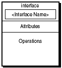
An interface, which is a collection of operations that specify a service (see Figure 3.4).
A component, which is the physical part of a system that provides the realization of a set of interfaces (see Figure 3.5).
A node, which is the physical part of a system that exists at runtime and provides a computational resource, such as a J2EE server (see Figure 3.6).
Behavioral elements, as the name suggests, are used to model the behavior of a system in response to specific events. UML supports two types of behavioral elements as follows:
An interaction, which constitutes a set of messages exchanged between a set of objects to accomplish a specific purpose (see Figure 3.7).
The state machine, which is used to represent the states that an object goes through during its lifetime in a system (see Figure 3.8).
Grouping elements provide a means to organize the UML structural and behavioral elements through the employment of package elements. A package is basically a general purpose container into which related elements can be placed, similar to a folder or directory in an operating system (see Figure 3.9).
Package diagrams are optional to UML and not discussed in this chapter.
Annotational elements constitute the explanatory parts of a UML model. For example, the note element can be used to attach a comment to another element (see Figure 3.10).
During the Analysis phase a current list of system requirements are analyzed to understand, evolve, communicate, and establish what the system requirements will be for a technical solution to a business problem. The emphasis in the Analysis phase is to understand what the requirements do as opposed to how to implement the requirements, which is the primary focus of the Design phase. It is in the Analysis phase where UML can be first introduced.
In UML, use cases are the primary tool for analyzing and driving the specification for a system. The objective of the use cases is to model the external interactions of a system under consideration, by visually describing who will use the solution system and how will they use it.
In UML terminology, any user of the system is referred to as an actor, which can be a person or another entity, such as a software system that exists outside the bounds of the system being defined. Each actor plays a role and generates events that cause the system to perform a value-based scenario on its behalf. From scenarios you can understand the behavior of a system because they describe a specific sequence of events, from the triggering event that begins the scenario to its logical conclusion. Identifying who the actors are is key to the analysis of a system as the scope of the system and the required external interfaces begin to emerge when actors are identified.
A use case defines how an actor interacts with the system. Developing a use case is all about building a portfolio of scenarios and alternatives of how actors interact with a system and following through their interactions until you get a complete understanding of how the system should conceptually respond. A use case can encompass many scenarios, for example:
The most conventional or likely sequence of events to realize the goal of the actor, which is appropriately named the main flow.
Several legitimate alternative events to reach the actor’s goal.
Event exceptions when an event in the main flow fails.
The visualization of the use case is provided with the Use Case diagram. Associated with Use Case diagrams are textual artifacts called Use Case specifications that typically contain the following details:
The name of the use case.
A brief description of the use case.
A description of the pre-conditions that must be satisfied before the use case is invoked.
A descriptive list of system interactions that occur in the main scenario.
A description of any alternative scenarios performed by an actor to achieve the same result as the main scenario.
A description of any exception scenarios performed by an actor when unexpected conditions occur in the main scenario.
The contents of the use case specification are not specified by UML, and are completely at the discretion of the project team to specify. However, it is recommended that the granularity of the use case specification be at a level that eases the comprehension of the Use Case diagrams.
This section will enable you to understand how to develop Use Case diagrams by illustrating simple scenarios of a Customer interacting with a Library System under analysis, as illustrated in Figure 3.11.
The system under consideration is defined in the context of a System Boundary and is represented by a rectangle. In Figure 3.11, the System Boundary is the Library System.
Actors are represented as stick figures. The only Actor in Figure 3.11 is the Customer because it is the only external entity interacting with the Library System and initiating the following use cases:
Reserve Book
Cancel Book reservation
Pickup Reserved Book
Borrow Book
Renew Book
Return Book
Pay Late Return Fee
Charge Account
The UML notation illustrated in Figure 3.12 represents UML entities and concepts that are not people but nevertheless interact with the system, such as organizations, hardware or software systems, and date/time-based systems.
The use cases performed by the Customer actor are represented as bubbles, as illustrated in Figure 3.11.
The connection between actors and associated use cases is known as a communication association (communication for short) and is represented as a single line between an actor and a use case, as illustrated in Figure 3.11.
Generalizations or parent-child relationships between use cases are annotated as a line with a triangular arrow head toward the parent use case. An example of a use case generalization is illustrated in Figure 3.11, where the Pay Late Return Fee is a parent use case and Charge Account is the child.
When one use case can be factored out of two or more use cases, the relationship between the use cases is known as an include relationship and is annotated as a dotted line with an <<include>> label. In Figure 3.11, the Borrow Book use case can be factored out of the Pickup Reserved Book and Renew Book use cases.
When one use case is a variation of another, the relationship between the two use cases is known as an extend relationship and is annotated as a dotted line with an <<extend>> label. The extension point, which determines when the extended case is appropriate, is written inside the base use case. In Figure 3.11, the extend relationship can be seen between Pay Late Return Fee and the Reserve Book, Borrow Book, and Return Book use cases. The extension point in the Pay Late Return Fee use case is “No Fine Due.”
It is good practice to link all UML diagrams created in the Analysis and Design phases to their source Use Case diagrams. This practice provides direct traceability from the analysis into the design of a software solution. This capability is organized in the Together ControlCenter by creating hyperlinks from the original Use Case diagram to the other analysis and design UML diagrams that support it. Remember, you will create multiple UML diagrams to describe the various aspects of your software solution.
In Together ControlCenter the diagrams that you create are grouped by the type of diagram—all the Class diagrams are grouped together, Sequence diagrams are grouped, and Collaboration diagrams are grouped. Very often, the same Class diagrams support multiple use cases. When this occurs, you can hyperlink the Use Case diagram to the existing Class diagram. This encourages software reusability, which is always a design goal.
UML Class diagrams are imperative to any object-oriented design effort, as they provide the static design view of the solution system and the structure of the code that will be produced in the development effort. However, they can also be used in the Analysis phase, where they are aptly known as conceptual models. The objective of a conceptual model is to capture the concepts that need to be addressed by a system, the properties of those concepts, and how they are related. A byproduct of developing conceptual models is a greater understanding of a system’s business context, because the captured concepts will be derived from the stakeholder’s perspective and vocabulary. Because conceptual models are drafted in the Analysis phase, they will not be as rich as traditional Class diagrams, which will be discussed later in this chapter. However, they do provide a great foundation for the Class diagrams that will be produced in the Design phase.
The idea behind conceptual modeling is to capture the primary concepts or ideas behind the solution system, with which the stakeholders must be familiar. Concepts can be derived directly from a system’s requirements specification, for example by extracting the following candidate concepts:
Tangible objects
The roles of end-users
Transaction types
Places and locations
Organizations
Events
Note
This list only provides examples of candidate concepts and should not be used as a complete reference for identifying concepts.
Alternatively, concepts can be derived from facilitated workshops geared towards identifying concepts with the stakeholders. It is important to ensure the concepts that are identified have structural attributes that further describe the concept in the context of the stakeholder business environment. UML does not specify how you can develop conceptual diagrams; it only provides the notation to capture them, which is illustrated in Figure 3.13.
Note
A UML representation of a concept does not contain any associated behavior because it is more aligned with the design of a system rather than the analysis.
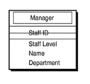
Referencing Figure 3.13, an example of a Manager concept, including its attributes, is illustrated in Figure 3.14.
Relationships between concepts in UML are expressed as a single line called an association. Each association has a descriptive name and a multiplicity (cardinality) that describes the number of instances a concept can participate in the relationship. The multiplicity is expressed as a number at the ends of an association using the following syntax:
* means many (zero or more).
1..* means one or more.
1..n, means 1 to exactly n, where n is a specific number.
m..n, means m through to exactly n, where m and n are specific numbers.
For example, Figure 3.15 illustrates a relationship where one CEO concept manages one or more Director concepts.
When drawing a conceptual model, the best approach is to take one concept, identify all its associations and cardinalities with other concepts, and then move to the next concept and apply the same approach and so on.
A Class diagram created in the Design phase provides a visual representation of each class that is contributing to a Use Case realization. Class diagrams are an essential aspect of any design effort because they directly portray the code that will be developed for a system. UML does not provide a mechanism for developing a Class diagram. However, the information needed to identify classes and their associated relationships can be derived directly from a conceptual model, if it exists, or from the objects that can be identified from the respective use case.
A Class diagram represents each class as a table with the following three sections:
For the UML notation for representing a class, refer to Figure 3.3.
The relationships between classes within a Class diagram are represented by connecting lines indicating either an association or generalization-type relationship. The type of relationship is indicated by the line style.
Relationships between classes are expressed as associations with a navigability arrow indicating which direction the association can be traversed or queried. If multiplicity is not indicated, the association is assumed to be a one-to-one relationship between the classes. An example of a one-to-five through 10 association is illustrated in Figure 3.16.
When the association between two classes is not obvious, a role name can be used to uniquely identify one end of an association. In most cases, the class or an attribute name that clarifies the association can be used as the role name. Figure 3.17 illustrates how the multiplicity and role names can be placed on an association.

Figure 3.17. The UML notation for using multiplicity and role names together on the same association.
When using role names and multiplicity with associations, the class diagram can become quite complicated to read. It is important when reading an association between two classes that you read from one specific direction (class), using the navigability arrow to follow the association to the target role and multiplicity. For example, the associations illustrated in Figure 3.18 can be described as follows:
A lecturer teaches many (zero or more) courses.
Each course has many (zero or more) lecturers and between 10 and 20 students.
A student takes many (zero or more) courses.
To support the design of object-oriented systems, UML supports three special types of associations in the context of Class diagrams: Reflexive, Aggregation, and Composition associations.
A Reflexive association describes an association relationship between objects of the same class. Such a recursive association is shown as an association that originates and terminates at the same class. For example, Figure 3.19 illustrates a reflexive association where a person manages many persons in the role of staff and a person is managed by zero or one person in the role of manager.
An Aggregation association describes an association between a class (the container class) that can be aggregated from other classes (aggregate classes). An Aggregation association is drawn with an open diamond tip pointing to the container class from the aggregate classes. A feature of the container class is that it has the aggregate class as an attribute, but does not control the life span of the aggregate class. An example of an Aggregation association is illustrated in Figure 3.20, where a computer is an aggregation of the CPU, disk, memory, and video card classes.
A Composition association is a stronger form of Aggregation association in that it implies the container class cannot exist without its composite (aggregate) classes. A composition relationship is drawn as a filled diamond tip pointing to the container class. An example of a Composition association is illustrated in Figure 3.21, where a book cannot exist without a cover.
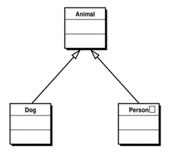
Generalization relationships support the concept of inheritance (reuse) in UML Class diagrams, where common attributes and operations are factored out of similar classes and assigned to a broader superclass (base class). Classes that inherit the attributes and operations of a superclass are known as subclasses (derived classes). A subclass can override the inherited attributes and operations, or add its own attributes and operations to them.
Note
The process of defining subclasses is known as specialization and is applicable in Use Case diagrams to represent inheritance.
In UML a generalization relationship is indicated with an arrow head pointing at the superclass. Figure 3.22 illustrates a generalization relationship where an Animal class is the superclass and the Dog and Person classes are its subclasses.
Interaction diagrams are about deciding and modeling how your system will achieve what you described in your use case models. Interaction diagrams enable you to visualize, specify, construct, and document the dynamics of how each object in your system interacts (exchanges messages) in order to perform a particular task. The context of a task equates to a single use case scenario.
UML provides two types of interaction diagrams that can be used to model the interactions between objects within the context of a use case scenario: Sequence and Collaboration diagrams. The Sequence and Collaboration diagrams represent two dynamic perspectives to view exactly the same information as they both model the messages that are passed between objects. Also, Sequence and Collaboration diagrams are isomorphic, implying that you can easily derive one from the other. In fact, most modeling tools, such as the Together ControlCenter, will automatically generate one diagram from the other.
Distinctions between the Sequence and Collaboration diagrams exist in how they portray the same information, as follows:
Sequence diagrams detail how chronological operations are carried out, what messages are sent, and when. The primary focus of a Sequence diagram is the flow of control by time, which promotes its use for modeling real-time scheduling systems and capturing the chronological sequence of interactions between objects in the context of a use case.
Collaboration diagrams convey the same information as Sequence diagrams, but focus on object roles and structural interdependencies. This focus promotes the use of Collaboration diagrams for illustrating the flow of control by organization between objects that interact.
Both Interaction diagrams provide a visual representation of the objects in a system’s design and the order they send messages to each other. In UML terminology, sending a message refers to calling one of the operations (methods) of an object. Hence, the Class diagrams in conjunction with the Interaction diagrams can provide an initial platform to begin coding a solution.
Because Sequence and Collaboration diagrams are isomorphic, you can learn how to model one of them and catalyze your comprehension of the other through the use of a professional modeling tool, which can perform the conversion between the two model types. The following section will describe the most common features of a Sequence diagram.
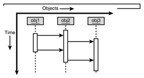
As illustrated in Figure 3.23, a Sequence diagram has two dimensions:
Note
The axes can be interchanged, so that time proceeds horizontally to the right and different objects are shown as horizontal lines.
The control of flow by time in a use case scenario is represented in a Sequence diagram through the following:
Objects that interact in the context of a use case. The objects that initiate interactions are typically placed on the left of the object dimension, with subordinate objects to their right.
An object lifeline represents the existence of an object over a period of time. Objects that exist throughout an interaction should appear at the top of the object dimension with their lifelines drawn parallel to the Time dimension. Objects that are created and destroyed dynamically (transient objects) have object lifelines that begin and end with a receipt of a message.
A focus of control, also known as the Activation bar, illustrates the period of time an object is performing an action. Actions can either be performed directly by an object, or through a subordinate object to which it has sent messages.
Links provide a semantic connection between objects. They serve as a path along which one object can dispatch a message to another object.
Messages specify communication from one object to another, with an expectation that an activity will be performed by the recipient object.
Figure 3.24 illustrates how you can represent objects, object lifelines, focus of control, links, and messages in the context of a Sequence diagram.
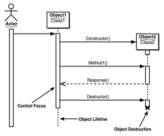
Figure 3.24. The representation of objects, object lifelines, focus of control, links, and messages in the context of a Sequence diagram.
In addition to the basic flow of control, as illustrated in Figure 3.24, you can also represent the following control flows in a Sequence diagram:
Selection, as illustrated in Figure 3.25.
Recursion, as illustrated in Figure 3.26.
Iteration, as illustrated in Figure 3.27.
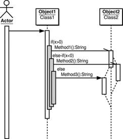
The Sequence diagram in Figure 3.28 represents the focus of control, conditional selection, recursion, creation, and destruction aspects of a Sequence diagram.

Figure 3.28. The representation of a focus of control, conditional selection, recursion, creation, and destruction aspects of a Sequence diagram.
The Collaboration diagram for the Sequence diagram represented by Figure 3.28 is illustrated in Figure 3.29, which can easily be generated using a professional modeling tool.
Note
A Sequence and Collaboration diagram based on a use case scenario is described in the section “UML By Example—The Book Store,” which appears at the end of this chapter.
Tip
Because object-oriented software development is an iterative process, it is often very helpful to write some prototype code to help solidify the design. This becomes evident while developing Sequence diagrams, where you may realize that you need a message that is not yet an operation in the Class diagram. You must therefore update the Class diagram to include the new operation. To maintain traceability, any modifications to your analysis or design must be put back into all affected diagrams. This is not as bad as it sounds if you are using a professional UML modeling tool, such as the Together ControlCenter.
The Statechart diagram shows the sequence of object states a single class can exhibit during its lifetime, together with the events that cause the changes of state. This is in contrast to the Interaction diagrams, which show the interaction between multiple classes.
The classes of objects that a Statechart examines can be derived from UML diagrams, such as Use Case, Class, or Interaction diagrams. The intent is not to develop Statechart diagrams for every class in a system—only those that show variable or complex behavior (reactions) to events dispatched from outside their context should be considered. For example, in the Model, View, Control (MVC) design pattern, it is the responsibility of the Control to react to events. For this reason, the behavior of the Control is a good candidate for a Statechart diagram.
Note
Statechart models are ideal for describing the behavior of a single class. Their biggest limitation is that they are not good at describing behavior that involves several classes. For such cases you can use an Interaction or an Activity diagram.
A Statechart is typically comprised of the following elements:
A state belongs to a single class and represents a combination of possible attribute values that the objects of this class may assume during the life of the class. The UML notation for representing states is illustrated in Figure 3.8.
An event is the occurrence or stimuli that triggers a state transition. For example, an object receives a message. Events can also have arguments that are passed from state to state as well as actions, which are regarded as atomic operations that prematurely terminate.
A transition is a relationship between two states. It implies that when a change of state is caused by an event in the first state, the object will move to the second state. All events exist in the context of transitions, as illustrated in Figure 3.30.
Figure 3.31 illustrates an example Statechart diagram that has been derived from a Sequence diagram.
An Activity diagram is a special form of state diagram that is used to model a sequence of behaviors and conditions taking place within the context of a workflow process. In many perspectives, Activity diagrams are similar to flow charts, except they have the capability to model parallel as well as sequential processes.
Activity diagrams can be used to examine workflow logic related to many scenarios, for example:
Within a complex operation in an object.
Across a single or several use case scenarios.
Within a business process.
Activity diagrams are the perfect UML tool for depicting the flow of activities within workflow type scenarios in your system. However, they do not provide details about how objects behave or collaborate with each other, which is an important aspect of any design process. For this reason, Activity diagrams should be used in conjunction with Statechart or Interaction diagrams.
Activity diagrams are read from top to bottom and typically consist of the following elements:
Activities or activity states, which represent the invocation of an operation, a step in a business process, or an entire business process.
Transitions or threads, which represent the flow of control from one activity to another through a link between the activities. A transition that involves an object is known as an object flow.
Branches, where a transition splits into two or more mutually exclusive alternatives.
Merger, where two or more transitions resulting from a branch combine.
Forks, a point where a transition splits into two or more other transitions, all of which are taken. A fork is a mechanism to represent concurrent processing. This is in contrast to a branch where only one of the transitions is taken as the path to the next activity.
Swimlanes, which represent a mechanism to group activities performed by the same organizational units.
Note
If an Activity diagram is used to model the flow of activities in a Use Case scenario, the swimlanes would identify which actor is performing the activity.
A sample Activity diagram is illustrated in Figure 3.32.
UML provides two types of diagrams that provide insight into how the final software solution will be implemented. These diagrams are the Component and Deployment diagrams.
The Component diagrams are extremely useful for architects and developers as they provide a static implementation model of the software components and their respective dependencies that will eventually constitute the solution system, which from a development perspective is the light at the end of the tunnel.
The components modeled in the Component diagram are primarily derived from the UML Class diagrams and can be represented as source code, binary code components, and executable components. Components are connected by dependencies, which implies that one component uses the services of the other.
The elements of a Component diagram are illustrated in Figure 3.33:
One of the key tasks that a software architect has to perform is to decide the application and hardware infrastructure that is required to support the final solution. Deployment diagrams are the appropriate UML diagrams to capture infrastructure decisions because they graphically represent processing resources (nodes), and the runtime instances of software components that can reside on them. If your application is distributed, a Deployment diagram is essential. By visually mapping software components to their respective executable environments (Nodes), you can examine such deployment issues as fault-tolerance and single-points of failure, and identify possible performance problems.
Note
The Deployment diagram is related to the Component diagram because the components typically exist in the context of a node.
The elements of a Deployment diagram are illustrated in Figure 3.34:
Nodes represent a physical processing resource, for example a J2EE server that participates in the deployment effort of a system.
Associations represent the connection protocol between nodes, for example TCP/IP and HTTP.
Components represent the runtime software modules of the software solution, for example Servlets, JavaServer Pages, and Enterprise JavaBeans.
An example of a simple J2EE application Deployment diagram is illustrated in Figure 3.35.
This section will describe a simple requirement for a Book Store system and explain how you can derive a use case from the requirements specification and the Activity, Class, and Interaction diagrams from the use case.
The requirements for the Book Store system are as follows:
A Customer can browse a catalog of all available books.
A Customer can search for books by title or author.
An analysis of the requirements will provide you with a list of Actors and how they will use the Book Store system; these are your use cases. The idea is to create as many use cases as necessary to fully describe the system requirements.
The derived actors for the Book Store use case are as follows:
Customer
Catalog
The derived use case scenarios for the Book Store are as follows:
Use Case 1: The customer browses the catalog.
The Book Store enables customers to browse all entries in the catalog. The only error condition is that the customer does not find any books of interest. The alternative flow requests the customer to fill out a survey.
Use Case 2: The book store enables customers to search the catalog by title and author.
This use case has the same alternative flow as Use Case 1. In fact, browsing the catalog can be thought of as searching for every book by every author. Use Case 2 is actually a specialization of Use Case 1. The Use Case diagram, as illustrated in Figure 3.36, visualizes this relationship as a generalization.
Most likely your projects will have multiple use cases from which to derive the design. The objective is to realize each use case into a system design in a methodical manner using UML. Trying to design all of the classes for the entire application at the same time would be an overwhelming and discouraging undertaking. Also, in the real world, you will be working with a group of developers, where each developer can concurrently design different parts of the application from individual use cases.
From the use case, the next step is to create an Activity diagram. This will give you a more complete understanding of the use case before creating Class diagrams. The Activity diagram maps very well to the scenario and alternatives given by a use case. The Book Store Activity diagram is illustrated in Figure 3.37.
The swimlanes in the Activity diagram show who is performing the actions. The Customer performs “search catalog” which causes a transition to Catalog to “perform query.” A decision is used to indicate the alternative flow requiring “fill out form” to be performed by the Customer.
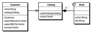
To derive a Class diagram, you must refer to the Use Case and Activity diagrams. The Activity diagram in Figure 3.37 indicates the Customer has an association with the Catalog. The Use Case specification indicates that a customer must provide an operation to search the catalog. This requirement, in turn, shows the need for a Book object that is returned from the search. Now that you have reviewed and evaluated the Activity diagram, you can create your Class diagram. Figure 3.38 illustrates the realization of the Book Store Use Case in the form of a Class diagram.
From Figure 3.38, you can identify the following:
Customerhas an association withCatalog.Cataloghas a composition of multiplicity 0..* to theBookclass.
As you may have guessed, the Book Store Sequence diagram, Figure 3.39, was completely generated by the Together ControlCenter. This tool enables you to generate a Sequence diagram from selected methods in a Class diagram. This is an extremely powerful capability of the design tool. The generated Sequence diagram is also shown as a Collaboration diagram in Figure 3.40, which was also auto-generated by the Together ControlCenter.


