Chapter 8. Ports and Interfaces
This chapter covers the following subjects:
![]() Rear Panel Port Clusters—This section shows you typical rear-panel port clusters and identifies each port.
Rear Panel Port Clusters—This section shows you typical rear-panel port clusters and identifies each port.
![]() USB—In this section, you learn about the many flavors of USB and USB connectors, including the latest, USB 3.1 and USB Type C, and how USB can also be adapted to network and legacy devices.
USB—In this section, you learn about the many flavors of USB and USB connectors, including the latest, USB 3.1 and USB Type C, and how USB can also be adapted to network and legacy devices.
![]() FireWire (IEEE 1394)—This section covers both FireWire 400 and FireWire 800 ports and cables
FireWire (IEEE 1394)—This section covers both FireWire 400 and FireWire 800 ports and cables
![]() SATA and eSATA—This section details the cabling and performance of SATA and eSATA’s three generations.
SATA and eSATA—This section details the cabling and performance of SATA and eSATA’s three generations.
![]() Thunderbolt—Intel developed it, Apple embraced it, and it’s also showing up on more and more high-performance Windows PCs. Learn about the performance and versatility of Thunderbolt in this section.
Thunderbolt—Intel developed it, Apple embraced it, and it’s also showing up on more and more high-performance Windows PCs. Learn about the performance and versatility of Thunderbolt in this section.
![]() Video—As the industry continues to move from analog to digital connectors, this section helps sort out the differences between VGA, DVI, HDMI, DisplayPort, and older standards you might encounter in configuring PCs, HDTVs, and home theater systems.
Video—As the industry continues to move from analog to digital connectors, this section helps sort out the differences between VGA, DVI, HDMI, DisplayPort, and older standards you might encounter in configuring PCs, HDTVs, and home theater systems.
![]() Audio—Color-coding and SPDIF differences are the focus of this section.
Audio—Color-coding and SPDIF differences are the focus of this section.
![]() PS/2—The PS/2 port continues to show up on desktop systems, and this section covers the variations you will find on some systems.
PS/2—The PS/2 port continues to show up on desktop systems, and this section covers the variations you will find on some systems.
Although USB is the most versatile of I/O ports, it’s scarcely alone on a typical PC. In this chapter, you learn about the home for most connections, the rear port cluster, and the many different types of ports, cables, and uses that enable a PC to work with many different types of peripherals and devices.
220-901: Objective 1.7 Compare and contrast various PC connection interfaces, their characteristics and purpose.
220-901: Objective 1.11 Identify common PC connector types and associated cables.
Foundation Topics
Rear Panel Port Clusters
Most of the external I/O ports discussed in this chapter are located in the port cluster, which is located at the rear of ATX, microATX, and mini-ITX motherboards. Figures 8-1 and 8-2 compare some typical port cluster designs and identify the ports. Use these figures as a reference when you learn more about each port type.


USB
Universal Serial Bus (USB) ports have almost completely replaced PS/2 (mini-DIN) mouse and keyboard ports on recent systems and can be used for printer, mass storage, and other external I/O devices. Some form of USB port is also used by most mobile devices, game consoles, many network devices, cars and trucks, smart TVs, and other electronics, making it truly “universal.”
Most recent desktop systems have at least eight USB ports and many systems support as many as 10 or more front- and rear-mounted USB ports. Laptops typically have three or four USB ports and Windows and Android tablets typically have at least one USB or USB-On-the-Go port. OS X desktop and laptop computers feature two or more USB ports.
USB ports send and receive data digitally.
There are three standards for USB ports included in the A+ Certification exam:
![]() USB 2.0 (also called Hi-Speed USB)
USB 2.0 (also called Hi-Speed USB)
![]() USB 3.0 (also called SuperSpeed USB)
USB 3.0 (also called SuperSpeed USB)
Note
A fourth standard, USB 3.1, was introduced in 2015. To learn more about USB 3.1, see “USB 3.1,” this chapter, p.206.
USB packaging and device markings frequently use the official logos shown in Figure 8-3 to distinguish the four versions of USB in common use. The industry uses the term Hi-Speed USB for USB 2.0, SuperSpeed USB for USB 3.0, and SuperSpeed+ USB for USB 3.1 Gen 2.

Figure 8-3 The USB logo (left) is used for USB 1.1–compatible devices, the Hi-Speed USB logo (second from left) is used for USB 2.0–compatible devices, the SuperSpeed USB logo (second from right) is used for USB 3.0–compatible devices, and the SuperSpeed+ USB logo (right) is used for USB 3.1 Gen 2–compatible devices. Devices bearing these logos have been certified by the USB Implementers Forum, Inc. (USB-IF). Images courtesy of USB-IF.
With any version of USB, a single USB port on an add-on card or motherboard is designed to handle up to 127 devices through the use of multiport hubs and daisy-chaining hubs. USB devices are Plug and Play (PnP) devices that are hot swappable (can be connected and disconnected without turning off the system).
Need more USB ports? You can add USB ports with any of the following methods:
![]() Motherboard connectors for USB header cables
Motherboard connectors for USB header cables
![]() Hubs
Hubs
![]() Add-on cards
Add-on cards
Some motherboards have USB header cable connectors, which enable you to make additional USB ports available on the rear or front of the computer (refer to Chapter 3, “Motherboard Components”). Some motherboard vendors include these header cables with the motherboard, whereas others require you to purchase them separately. Most recent cases also include front-mounted USB ports, which can also be connected to the motherboard. Because of vendor-specific differences in how motherboards implement header cables, the header cable might use separate connectors for each signal instead of the more common single connector for all signals.
USB generic hubs are used to connect multiple devices to the same USB port, distribute both USB signals and power via the USB hub to other devices, and increase the distance between the device and the USB port. There are two types of generic hubs:
![]() Bus-powered
Bus-powered
![]() Self-powered
Self-powered
Bus-powered hubs might be built in to other devices, such as monitors and keyboards, or can be standalone devices. Different USB devices use different amounts of power and some devices require more power than others. A bus-powered hub provides no more than 100 milliamps (mA) of power to each device connected to it. Thus, some devices fail when connected to a bus-powered hub.
A self-powered hub, on the other hand, has its own power source; it plugs in to an AC wall outlet. A self-powered hub designed for USB 1.1 or USB 2.0 devices provides up to 500mA of power to each device connected to it, whereas a self-powered hub designed for USB 3.0/3.1 devices provides up to 900mA of power to each device. Note that USB hubs are backward compatible to previous USB versions. A self-powered hub supports a wider range of USB devices than a bus-powered hub, and I recommend using it instead of a bus-powered hub whenever possible.
Add-on cards can be used to provide additional USB ports as an alternative to hubs. One advantage of an add-on card is its capability to provide support for more recent USB standards. For example, you can add a USB 3.0 card to a system that has only USB 1.1/2.0 ports to permit use of USB 3.0 hard drives at full performance. Add-on cards for USB 1.1 or USB 2.0 ports connect to PCI slots on desktop computers and CardBus or ExpressCard slots on laptop computers, whereas USB 3.0 cards connect to PCIe x1 or wider slots on desktop computers and ExpressCard slots on laptop computers.
Figure 8-4 illustrates a typical USB 3.0 card, a USB 2.0 self-powered hub, and a USB 2.0 port header cable.

Table 8-1 provides an overview of current USB standards.

USB 1.1 and 2.0
USB 1.1 and 2.0 standards use the same cable and connector types, which are shown in Figure 8-5.

USB 1.1/2.0 cables use two different types of connectors: Series A (also called Type A) and Series B (also called Type B). Series A connectors are used on USB root hubs (the USB ports in the computer) and USB external hubs to support USB devices. Type A cables can also connect to USB 3.0 root hubs and external hubs.
Series B connectors are used for devices that employ a removable USB cable, such as a USB printer or a generic (external) hub. Generally, you need a Series A–to–Series B cable to attach most devices to a USB root or external hub. Cables that are Series A–to–Series A or Series B–to–Series B are used to extend standard cables and can cause problems if the combined length of the cables exceeds recommended distances. Adapters are available to convert Series B cables into Mini-B cables, which support the five-pin Mini-B port design (also known as the USB connector type mini) used on many recent USB devices.
USB-on-the-Go uses the USB connector type micro (micro-B) connector shown in Figure 8-5. USB-on-the-Go is used by most Android smartphones and tablets for charging and file sync.
USB 1.1 ports run at a top speed (full-speed USB) of 12 megabits per second (Mbps); low-speed USB devices, such as a mouse or a keyboard, run at 1.5Mbps; and USB 2.0 (Hi-Speed USB) ports run at a top speed of 480Mbps. USB 2.0 ports are backward compatible with USB 1.1 devices and speeds and manage multiple USB 1.1 devices better than a USB 1.1 port does.
The maximum length for a cable attached to 12Mbps or 480Mbps USB devices is 5 meters, whereas the maximum length for low-speed (1.5Mbps) devices, such as mice and keyboards, is 3 meters.
USB 3.0
USB 3.0 ports run at a maximum speed of 5Gbps and are backward compatible with USB 1.1 and USB 2.0 devices and speeds.
USB 3.0 Standard-A connectors are similar to USB 1.1/2.0 Series A connectors but have additional contacts. Most port cluster connectors are marked in blue (refer to Figures 8-1 and 8-2). They are compatible with any USB cable. However, USB 3.0 Series B connectors are available in two forms: Standard-B and Micro-B. Micro-B was originally intended for mobile devices but is often used by both portable and desktop USB 3.0 hard drives. USB 3.0 Type B and Micro Type B cables can be used only with USB 3.0 devices. USB 3.0 designs also include Micro-AB and Micro-A, but these are not in common use. Figure 8-6 illustrates USB 3.0 Standard-B and Micro-B cables and receptacles.

USB 3.1
USB 3.1 is actually two standards in one:
![]() USB 3.1 Gen 1 is the new name for USB 3.0. Anytime you see a reference to USB 3.0, keep in mind that USB 3.1 Gen 1 is the same standard. Although USB 3.1 Gen 1 is the same standard as USB 3.0, vendors continue to use the original USB 3.0 name.
USB 3.1 Gen 1 is the new name for USB 3.0. Anytime you see a reference to USB 3.0, keep in mind that USB 3.1 Gen 1 is the same standard. Although USB 3.1 Gen 1 is the same standard as USB 3.0, vendors continue to use the original USB 3.0 name.
![]() USB 3.1 Gen 2 is where the new features in USB 3.1 are located. USB 3.1 Gen 2 (often referred to simply as USB 3.1) runs at speeds up to 10Gbps (2× the speed of USB 3.0/USB 3.1 Gen 1). It is backward compatible with USB 1.1, 2.0, and 3.0/3.1 Gen 1.
USB 3.1 Gen 2 is where the new features in USB 3.1 are located. USB 3.1 Gen 2 (often referred to simply as USB 3.1) runs at speeds up to 10Gbps (2× the speed of USB 3.0/USB 3.1 Gen 1). It is backward compatible with USB 1.1, 2.0, and 3.0/3.1 Gen 1.
Both USB 3.1 Gen 1 and Gen 2 use the same cables and connectors as USB 3.0. However, some USB 3.1 Gen 2 ports support a new reversible connector, USB Type C, which can be used by both hubs and devices. Some systems, such as the second motherboard shown in Figure 8-1, include both a Type C USB 3.1 port and a standard Type A USB 3.1 Gen 2 port.
Note
Although USB Type-C connectors also support older USB standards, it is unlikely that vendors would use it for USB 3.0, USB 2.0, or USB 1.1 ports.
Figure 8-7 illustrates USB 3.0 Type A and Type C cable and USB 3.1 Gen 2 ports.

Other USB standards, such as USB Power Delivery and USB Battery Charging, will take advantage of other features in the USB Type C port. For more information about USB 3.1, USB Type C, USB Power Delivery, or USB Battery Charging, see the official USB website at www.usb.org.
USB Adapters
USB cable adapter kits enable a single cable with replaceable tips to be used for the following tasks:
![]() Type A male to female, to extend a short cable.
Type A male to female, to extend a short cable.
![]() Type A female to Type B connectors, to enable a single cable with multiple adapter tips to work with various types of peripherals (see Figure 8-8).
Type A female to Type B connectors, to enable a single cable with multiple adapter tips to work with various types of peripherals (see Figure 8-8).

![]() Type A female to USB-on-the-Go, for use with tablets or smartphones (see Figure 8-9).
Type A female to USB-on-the-Go, for use with tablets or smartphones (see Figure 8-9).

Figure 8-9 USB-on-the-Go to Type A adapter enables a standard USB cable to work with devices that use the Micro-A connector.
![]() USB to Ethernet, to enable a device without an Ethernet port to connect to a wired network (see Figure 8-10).
USB to Ethernet, to enable a device without an Ethernet port to connect to a wired network (see Figure 8-10).

![]() USB to legacy ports (USB to PS/2, USB to parallel, USB to serial). See Figure 8-11.
USB to legacy ports (USB to PS/2, USB to parallel, USB to serial). See Figure 8-11.

A hybrid keyboard or mouse is one designed to work with either USB or PS/2 ports. Adapters bundled with a mouse or keyboard, such as the ones shown in Figure 8-10, can be used only on mice or keyboards that are designed to work with either type of port. A USB to PS/2 adapter sold at retail stores can also work with PS/2-only devices.
FireWire (IEEE 1394)
FireWire, also known as IEEE 1394, is a family of high-speed, bidirectional, serial transmission ports that can connect digital devices to PCs, or digital devices to each other. FireWire also supported peer-to-peer networking with older versions of Windows, but this feature was discontinued starting with Windows Vista.
The most common version of FireWire is known as FireWire 400 (Firewire 400), and is also known as IEEE 1394a. Sony’s version is known as i.LINK. FireWire 400 has a maximum speed of 400Mbps and can be implemented either as a built-in port on the motherboard (refer to Figure 8-1) or as part of an add-on card (see Figure 8-12). FireWire 800 (IEEE 1394b or Firewire 800) runs at up to 800Mbps but is more often used on systems running OS X than those running Windows.

Figure 8-12 A typical FireWire 400 host adapter card with three external ports and one internal port.
Up to 16 FireWire devices can be connected to a single IEEE 1394 port through daisy-chaining. By using hubs, up to 63 devices can be connected to a single port. Most external FireWire devices have two ports to enable daisy-chaining.
FireWire cards for desktop computers can use PCI or PCI Express buses. (Versions for laptops use ExpressCard or CardBus designs.)
Maximum copper cable length is 4.5 meters; by using active (powered) repeaters or hubs, cables can be daisy-chained up to 72 meters. FireWire carries digital signals.
Table 8-2 compares FireWire 400 and 800 interfaces.

FireWire 400
Standard FireWire 400 ports and cables use a six-pin interface (four pins for data, two for power), but some digital camcorders and all i.LINK ports use the alternative four-pin interface, which supplies data and signals but no power to the device. Six-wire to four-wire cables enable these devices to communicate with each other. Refer to Figure 8.13.

FireWire 800
A faster version of the IEEE 1394 standard, FireWire 800 (also known as IEEE 1394b), runs at 800Mbps. FireWire 800 ports use a nine-pin interface. There are two versions of the FireWire 800 port: The Beta port and cable are used only for FireWire 800 to FireWire 800 connections, whereas the Bilingual cable and port are used for either FireWire 800 to FireWire 800 or FireWire 800 to FireWire 400 connections. Beta cables and ports have a wide notch at the top of the cable and port, whereas Bilingual cables and ports have a narrow notch at the FireWire 800 end and use either the four-pin or six-pin FireWire 400 connection at the other end of the cable. All four cable types are shown in Figure 8-13.
SATA and eSATA
The vast majority of desktop and laptop computers in use rely on the Serial ATA (SATA) interface to connect to internal hard disk drives, SSDs, and optical drives. The external version of SATA, eSATA, is not as common, but has been widely used by high-performance Windows and Linux-based desktop computers for external hard disk drives.
Both SATA and eSATA interfaces carry data digitally using high-speed serial transmission, but vary in speeds and connection details. For speed differences, see Table 8-3.

Low-performance and older high-performance desktop motherboards feature top-facing SATA cable headers (see Figure 8-14). However, many recent high-performance motherboards have switched to front-facing SATA cable headers (see Figure 8-15).


SATA Configuration and Cabling
Figure 8-16 compares the power and data connectors and cables used by typical SATA drives.

An SATA drive has a one-to-one connection to the corresponding SATA interface on the motherboard. Drive jumpers on SATA drives, when present, are used to reduce drive interface speed from the default to the next lower speed (from 6.0Gbps to 3.0Gbps or from 3.0Gbps to 1.5Gbps). See the specific drive’s documentation for details.
SATA 1.5Gbps (SATA1) and 3.0Gbps (SATA2) drives and interfaces use the same cabling. However, SATA 6.0Gbps (SATA3) drives and interfaces use an improved version with heavier shielding for greater reliability. Cables made for SATA 6.0Gbps are typically marked as such and can also be used with slower SATA drives and interfaces. All SATA data cables use an L-shaped seven-pin connector, and all SATA power cables use a larger L-shaped 15-pin connector as shown in Figure 8-16.
SATA Express, also known as SATAe or Serial ATA Revision 3.2, was announced in 2014. It uses the PCI Express (PCIe) bus to achieve data transfer rates up to 16Gbps. Although Intel’s Z97, H97, and X99 chipsets include support for SATAe, no SATAe drives are currently available. The SATAe host adapter can also be used by two standard SATA 6Gbps or slower drives. For more information about SATAe, see the Serial ATA International Organization website at http://sata-io.org/.
SATA data cables are available with straight-through connectors on both ends or with a right-angle connector on one end for easier connection to SATA drives. Some cables, either straight-through or right-angle, include a metal clip to help lock the drive into place.
eSATA cable headers convert standard SATA headers into eSATA ports available from the rear of the system.
See Figure 8-17 for examples of these cables. For more detail, see Figures 6-11 and 6-12, p.143.

The SATA and eSATA drive interfaces are also designed to support hot-swapping but must be configured for AHCI mode (also known as native mode) in the system BIOS or UEFI firmware. If the interface is configured for IDE mode (also known as emulation mode), the drive connected to it cannot be hot-swapped and will also lose access to advanced SATA and eSATA features such as native command queuing (NCQ). RAID mode supports AHCI features along with allowing two or more drives to be used as a logical unit. See Figure 2-8 in Chapter 2, “Configure and Use BIOS/UEFI Tools,” for an example of this dialog.
Caution
If internal SATA hard disks are configured to support hot-swapping (configured as AHCI devices in the system BIOS/UEFI; it might also be necessary to enable hot-swapping as an additional option), they also show up when you open the Safely Remove Hardware and Eject Media dialog in the Notification area of Windows. Do not select these drives for removal.
Thunderbolt
Thunderbolt is a high-speed interface capable of supporting hard disk drives, SSDs, HDTVs up to 4K resolution, and other types of I/O devices. Thunderbolt includes PCIe and DisplayPort digital signals into a compact interface that runs from 2× to 8× faster than USB 3.0, and 2× to 4× faster than USB 3.1 Gen 2. Intel introduced Thunderbolt in 2011. Thunderbolt was initially adopted by Apple, which uses it in the recent and current MacBook product lines. Thunderbolt is also available on some high-end desktop motherboards using Intel chipsets.
Thunderbolt is available in three versions that use two different port types: Thunderbolt 1 and Thunderbolt 2, currently the most common version, use the same physical port as the mini-DisplayPort. The newest version, Thunderbolt 3, uses the same physical connector as USB Type C. All three versions support up to six Thunderbolt devices per port and use daisy chaining to connect devices to each other.
Table 8-4 compares Thunderbolt versions to each other.

Figure 8-18 compares a Thunderbolt 2 cable with a USB Type C cable (the cable used by Thunderbolt 3) and a mini-DisplayPort cable, which uses the same physical connector as a Thunderbolt cable.

Because of Thunderbolt’s high bandwidth, it can be connected to docks that feature multiple port types. Figure 8-19 shows a typical Thunderbolt 2 dock that also provides USB 3.0 ports, an HDMI video port, Gigabit Ethernet port, and audio headphone and microphone jacks.

Video
When selecting a monitor or projector for use with a particular video card or integrated video port, it’s helpful to understand the physical and feature differences between different video connector types, such as VGA, DVI, HDMI, DisplayPort Component/RGB, BNC, S-video, and composite. Table 8-5 provides an overview of these connector types.

VGA
VGA is an analog display standard. By varying the levels of red, green, or blue per dot (pixel) onscreen, a VGA port and monitor can display an unlimited number of colors. Practical color limits (if you call more than 16 million colors limiting) are based on the video card’s memory and the desired screen resolution.
The base resolution (horizontal×vertical dots) of VGA is 640×480. SVGA most typically refers to 800×600 VGA resolution.
All VGA cards made for use with standard analog monitors use a DB-15F 15-pin female connector, which plugs into the DB-15M connector used by the VGA cable from the monitor. Figure 8-20 compares these connectors.

DVI
The DVI port, a digital video port, is currently used by most LED and LCD displays with sizes under 25-inches diagonal measurement. The DVI port commonly comes in two forms: DVI-D supports only digital signals and is found on digital LCD displays. Most of these displays also support analog video signals through separate VGA ports.
DVI single-link omits some of the connectors in the DVI interface, limiting the maximum resolution. DVI dual-link uses all of the connectors, enabling higher resolutions than those possible with DVI single-link. See illustrations at https://en.wikipedia.org/wiki/Digital_Visual_Interface.
Most video cards with DVI ports use the DVI-I dual-link version, which provides both digital and analog output and supports the use of a VGA/DVI-I adapter for use with analog displays (refer to Figure 8-28). Figure 8-21 illustrates a DVI-D cable and DVI-I port.

The less-common DVI-A version supports analog signals only. The maximum length for DVI cables is 5 meters.
DVI and Copy Protection
Some integrated and card-based DVI-I and DVI-D connections (as well as some DVI connections in home theater equipment such as HDTVs, projectors, and DVD players) can support High-Bandwidth Digital Content Protection (HDCP). HDCP, a form of digital rights management (DRM), enables playback of DVD or other encrypted content at full resolution. HDCP support is also needed in the display. Some LCD/LED displays with DVI ports do not support HDCP. In such cases, encrypted video will play back at DVD-quality (480p) resolution.
HDMI
Video cards and systems with integrated video that are designed for home theater use support a standard known as High-Definition Multimedia Interface (HDMI). HDMI has the capability to support digital audio as well as video through a single cable. HDMI ports are found on most late-model HDTVs as well as home theater hardware such as amplifiers, Blu-ray and DVD players, and many recent laptop and desktop PCs running Windows or Linux. All versions of HDMI support HDCP and DRM.
The most recent HDMI standard, version 1.4b, supports 1080p HDTV and resolutions up to 4096×2160 (also known as 4K×2K), 48-bit color depths, various types of uncompressed and compressed digital audio, 3D over HDMI, and Fast Ethernet support. For more about HDMI specifications, visit www.hdmi.org.
The most common HDMI port is Type A, which has 19 pins. It is used to achieve high-definition resolutions such as 1920 × 1080 (known as 1080p or 1080i). The HDMI 1.3 and later specifications also define a mini-HDMI connector (Type C). It is smaller than the Type A plug but has the same 19-pin configuration. The HDMI 1.4 specification defines a micro-HDMI connector (Type D), which again uses the same 19-pin configuration but in a connector the size of a micro-USB plug.
HDMI hardware, regardless of the version in use, uses cables similar to the ones shown in Figure 8-22 and the ports shown in Figure 8-23. Typical cable lengths range up to 40 feet, but higher-quality copper cables can be longer.

DisplayPort
DisplayPort was designed by the Video Electronics Standards Association (VESA) as a royalty-free digital interface to replace DVI and VGA. It offers similar performance to HDMI but is not expected to compete with the HDMI standard.
Unlike HDMI or DVI, which can connect only one display per port, DisplayPort enables multiple displays to be connected via a single DisplayPort connector.
DisplayPort utilizes packet transmission similar to Ethernet and USB. Each packet transmitted has the clock embedded as opposed to DVI and HDMI, which utilize a separate clocking signal.
DisplayPort connectors are not compatible with USB, DVI, or HDMI; however, devices that support Dual-mode DisplayPort (DisplayPort++) technology are capable of sending HDMI or DVI signals with the use of the appropriate adapter. DisplayPort offers a maximum transmission distance of 3 meters over passive cable, and 33 meters over active cable. There are 20 pins in a DisplayPort connector, with pins 19 and 20 being used for 3.3V, 500 mA power on active cables. The mini-DisplayPort cable shown in Figure 8-22 also uses a 20-pin connector.
DisplayPort cables can be up to 15 meters long.
Figure 8-24 illustrates a high-performance video card with a DisplayPort connector.

DisplayPort Versions
DisplayPort is currently available in three versions:
![]() DisplayPort 1.1—maximum data transfer rate of 8.64Gbps.
DisplayPort 1.1—maximum data transfer rate of 8.64Gbps.
![]() DisplayPort 1.2—maximum data transfer rate of 17.28Gbps, introduces mini-DisplayPort connector, and support for 3D
DisplayPort 1.2—maximum data transfer rate of 17.28Gbps, introduces mini-DisplayPort connector, and support for 3D
![]() DisplayPort 1.3—maximum data transfer rate of 32.4Gbps with support for 4K, 5K, and 8K UHD displays
DisplayPort 1.3—maximum data transfer rate of 32.4Gbps with support for 4K, 5K, and 8K UHD displays
DisplayPort and Thunderbolt
The Thunderbolt digital I/O interface is backwards-compatible with mini-DisplayPort, so you can connect mini-DisplayPort displays to either a Thunderbolt or mini-DisplayPort connector.
RCA
The RCA connector can be used for both analog video (Composite) and stereo audio. Composite video cables use 75 ohm impedance, are usually yellow, and support standard definition video signals up to 480i, but do not support HDCP or other DRM technologies.
The recommended length for composite cables is up to 25 meters.
Refer to Figure 8-25 for a comparison of typical composite, S-video, and component video cables.

S-Video (Mini-DIN 4)
The mini-DIN 4 connector was used by some older video cards, camcorders, and home theater equipment to carry S-video (also known as C/Y) signals. S-video improves on the standard composite signal by splitting luma (brightness) and chroma (color) into separate channels for somewhat better picture quality than that available with composite video.
Like composite, S-video is analog and does not support any form of DRM. It supports up to 480i resolution.
Mini-DIN 6
The mini-DIN 6 connector, most commonly used for PS/2 mouse and keyboard connections, is also used to provide power, audio data, and video data connections for surveillance cameras. Cabling is available up to 300 feet in length.
Component
Some data projectors and virtually all HDTVs support a high-resolution type of analog video known as component video. Component video uses separate RCA cables and ports to carry red, green, and blue signals (RGB), and can support up to 720p or 1080i HDTV resolutions.
The maximum length of component cable varies with construction quality; some high-quality cables can work reliably in excess of 100 feet. Component video does not support HDCP or other types of DRM.
Figure 8-25 compares component, composite, and S-video cables. Figure 8-26 illustrates component, composite, and other connections on the rear of a typical surround-sound home theater receiver with video pass-through.

BNC Coaxial
A single-connection BNC coaxial cable can be used for composite video.
A 5BNC cable transmits red (red cable/connector), green (green cable/connector), blue (blue cable/connector), horizontal sync (black, gray, or yellow cable/connector), and vertical sync (white cable/connector) signals. A 5BNC cable can be used for component video or, with an adapter, VGA video. Some data projectors use the 5BNC connector.
BNC cables have an impedance of 75Ohms, carry analog signals, and do not support HDCP or other types of DRM. 5BNC cables are available in lengths up to 100 feet, and single-connection BNC cables are available in lengths up to 300 feet.
Figure 8-27 illustrates a typical 5BNC cable adapter to VGA.

Video Adapters and Converters
With so many different types of video connections in use today, it’s not always possible to match displays to video card or integrated video connector types. Because different types of physical connectors use the same signaling methods, adapters enable displays and video cards with different connectors to work together.
Thunderbolt to DVI
Because Thunderbolt supports mini-DisplayPort and uses the same physical connector, a mini DisplayPort to DVI adapter, such as the one shown in Figure 8-28, will also work to enable DVI displays to connect to Thunderbolt ports.

HDMI to VGA
As you learned earlier in this chapter, HDMI is a digital video connection, while VGA is an analog video connection. Although some vendors sell simple HDMI to VGA adapter cables, these often do not work due to a lack of power in the HDMI port on some laptops. Look for an adapter that has a USB or AC adapter power source to assure more reliable connections.
DVI to HDMI
Because HDMI uses the same video signals as DVI, DVI to HDMI cables or adapters are widely available.
DVI-I to VGA
DVI-I includes both VGA-compatible analog video and DVI digital video. The DVI-I to VGA adapters shown in Figures 8-28 and 8-29 enable VGA displays to work with DVI-I ports on video cards.

Audio
Motherboards with built-in audio always have analog jacks and some have digital ports as well.
Analog
The 1/8-inch (3.5mm) audio mini-jack (also known as the TRS jack) is used by sound cards and motherboard-integrated sound for speakers, microphone, and line-in jacks, as shown in Figures 8-1 and 8-2.
To avoid confusion, most recent systems and sound cards use the PC Design Guide PC 2001 color coding listed as follows:
![]() Pink—Microphone in
Pink—Microphone in
![]() Light blue—Line in
Light blue—Line in
![]() Lime green—Stereo/headphone out
Lime green—Stereo/headphone out
![]() Black—Rear stereo output
Black—Rear stereo output
![]() Gray—Side stereo output
Gray—Side stereo output
![]() Orange—Subwoofer
Orange—Subwoofer
The recommended maximum length for these cables is 10 meters.
Figure 8-30 illustrates microphone in, line-in, and stereo/headphone out cables and a typical motherboard’s integrated audio jacks.

Analog audio can connect to receivers and is used in gaming. However, for digital output (such as from a DVD or Blu-ray), you need digital audio. HDMI carries both digital video and audio, but for situations in which HDMI cannot be used (for example, with a receiver lacking HDMI inputs), you can use SPDIF digital output (refer to Figure 8-1, p.201, for typical examples).
SPDIF (Digital)
Many systems include both analog audio (delivered through 1/8-inch/3.5mm audio mini-jacks) and digital audio (refer to Figures 8-1 and 8-2). Sony/Philips Digital Interconnect Format (SPDIF, sometimes spelled S/PDIF) ports output digital audio signals to amplifiers, such as those used in home theater systems, and come in two forms: optical and coaxial.
Optical SPDIF uses a fiber-optic cable, whereas coaxial SPDIF uses a shielded cable with an RCA connector. The cables are shown in Figure 8-31.

Tip
By default, systems with both analog and digital output use analog output. To enable digital output, use the Hardware and Sound dialog in Windows Control Panel or the proprietary mixer provided with some sound cards or onboard audio devices.
Sound cards might incorporate SPDIF ports into the card (see Figure 8-32) or into drive bay or external extension modules.
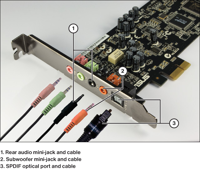
Figure 8-32 A PCIe sound card with support for 5.1 analog surround sound and an optical SPDIF output.
SPDIF digital audio ports support compressed and encrypted audio from sources such as DVD and Blu-ray movies.
PS/2
Although the PS/2 port is identified as a legacy port, it continues to be used for keyboards and mice in many recent systems, as shown previously in Figures 8-1 and 8-2. Unlike USB and FireWire, PS/2 ports do not support hot-swapping: you must shut down the system before connecting or removing a PS/2 device. PS/2 is sometimes referred to as Mini-DIN 6.
PS/2 Keyboard Port
When two PS/2 ports are stacked in a port cluster, the PS/2 keyboard port is the lower port and uses a purple connector.
PS/2 Mouse Port
When two PS/2 ports are stacked in a port cluster, the PS/2 mouse port is the upper port, and uses a green connector.
PS/2 Combo Port
Many systems have only a single PS/2 port, which might function as only a keyboard port, or might be marked half purple and half green, which indicates it can be used for either a mouse or keyboard. Refer to Figures 8-1 and 8-2 for examples of PS/2 keyboard, mouse, and combo ports. Refer to Figure 8-10 for examples of PS/2 connectors incorporated into USB to PS/2 adapters.
Exam Preparation Tasks
Review All the Key Topics
Review the most important topics in the chapter, noted with the Key Topic icon in the outer margin of the page. Table 8-6 lists a reference of these key topics and the page numbers on which each is found.

Complete the Tables and Lists from Memory
Print a copy of Appendix B, “Memory Tables” (found on the CD), or at least the section for this chapter, and complete the tables and lists from memory. Appendix C, “Answers to Memory Tables,” also on the CD, includes completed tables and lists to check your work.
Define Key Terms
Define the following key terms from this chapter, and check your answers in the glossary.
High-Definition Multimedia Interface (HDMI) HDMI
Digital (Optical connector)
Complete Hands-On Labs
Complete the hands-on labs, and then see the answers and explanations at the end of the chapter.
Lab 8-1: Evaluating Port Types and Performance
Examine a computer to learn the following:
![]() The number of USB 2.0 ports, USB 3.0 ports, and SATA ports.
The number of USB 2.0 ports, USB 3.0 ports, and SATA ports.
![]() Determine whether the SATA ports support SATA 6Gbps, 3Gbps, 1.5Gbps, or if some support the fastest speed, and some a slower maximum speed.
Determine whether the SATA ports support SATA 6Gbps, 3Gbps, 1.5Gbps, or if some support the fastest speed, and some a slower maximum speed.
![]() Determine if the computer supports 5.1 or 7.1 surround audio or digital audio playback.
Determine if the computer supports 5.1 or 7.1 surround audio or digital audio playback.
Use a combination of color-coding and the motherboard or system documentation to identify the ports.
Lab 8-2: Display Connections
Examine a computer to learn the following:
![]() The number of DVI, HDMI, VGA, and DisplayPort ports. Are the HDMI and DisplayPort ports full-size or are they mini-size?
The number of DVI, HDMI, VGA, and DisplayPort ports. Are the HDMI and DisplayPort ports full-size or are they mini-size?
![]() Are the ports built into the port cluster or are they on a video card (or cards)?
Are the ports built into the port cluster or are they on a video card (or cards)?
Assume that you need to connect the computer to the following types of displays:
![]() A legacy display with a VGA port
A legacy display with a VGA port
![]() A data projector with an HDMI port
A data projector with an HDMI port
![]() A display with a DisplayPort port
A display with a DisplayPort port
Determine whether you can connect the computer directly to each port type or if an adapter would be necessary. If an adapter would be necessary, which type of adapter is needed?
Keep in mind that for purposes of this lab we assume that each display has only a single port type. In reality, most displays and projectors have at least two port types that can be selected from an on-screen display.
Answer Review Questions
1. Identify the ports on the ATX motherboard in the following figure. (Note: You may need to use an answer more than one time.)

A. FireWire port
B. eSATA ports
C. Ethernet port
D. USB 2.0 ports
E. USB 3.0 ports
F. SPDIF coaxial port
G. SPDIF optical port
H. PS/2 mouse and keyboard ports
I. Audio jacks
2. Which of the following describes a USB 3.0 port? (Choose two.)
A. Runs at a maximum speed of 365Mbps
B. Runs at a maximum speed of 480Mbps
C. Runs at a maximum speed of 3.2Gbps
D. Runs at a maximum speed of 5Gbps
E. Usually color-coded blue
F. Usually color-coded yellow
G. Usually color-coded pink or red
3. Identify the connectors in the following figure.
A. USB Mini-AB
B. USB Mini-B five-pin
C. USB Type A Male
D. USB Type A Female
E. USB Type B
F. USB Mini-B four pin.
4. Your client wants to replace an SATA1 hard disk drive with an SATA3 SSD. Which of the following statements are correct?
A. SATA1 and SATA3 have the same transfer rate.
B. SATA3 has a 3Gbps transfer rate.
C. SATA3 has a 6Gbps transfer rate.
D. SATA3 cables are recommended for all SATA speeds.
E. SATA3 cables cannot be used with SATA1 or SATA2 drives.
F. SATA1 has a 1.5Gbps transfer rate.
5. Identify the type of port indicated on the motherboard in the following figure.

A. HDMI
B. SATA
C. USB 3.0
D. DVI
6. Which of the following options corresponds to the connector types in the figure?

A. HDMI
B. SATA
C. DVI
D. Thunderbolt 1/2
E. Mini-DisplayPort +
F. USB 2.0
G. USB 3.0
H. USB Type-C
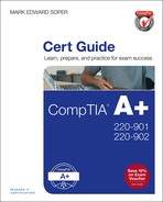
7. The following figure shows two typical PCIe video cards with a variety of ports. Which port carries a digital video signal only?

A. 1
B. 2
C. 3
D. 4
E. 5
8. Which of the following transmits both digital video and digital audio signals using a single cable?
A. DVI-I
B. VGA
C. DVI-D
D. HDMI
9. Identify the connectors in the following figure.


A. 5BNC
B. Composite
C. Component
D. S-video
10. Which of the following produces the best color?
A. Component video
B. Composite video
C. S-video
11. Identify the adapters in the following figure.

A. Mini DisplayPort to DVI-I
B. DisplayPort to HDMI
C. Mini DisplayPort VGA
D. Mini DisplayPort HDMI
E. DisplayPort to DVI-D
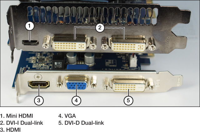
12. Identify the connectors and jacks in the following figure.

A. HDMI
B. SPDIF coaxial
C. Microphone
D. Keyboard
E. SPDIF optical
F. Headphones
Answers and Explanations for Hands-On Labs
Lab 8-1: Evaluating Port Types and Performance
To answer questions about USB 2.0 and USB 3.0 ports, keep these factors in mind:
![]() Some older systems might have no USB 3.0 ports at all.
Some older systems might have no USB 3.0 ports at all.
![]() Recent systems typically have two or four USB 3.0 ports.
Recent systems typically have two or four USB 3.0 ports.
Use the illustrations in Figures 8-1 and 8-2 to help determine the answer for the system(s) you examine.
To answer questions about SATA ports, you can try three methods:
![]() If you can safely open the system, you can examine the SATA ports. Sometimes they are marked with their maximum speed. If not, check the BIOS settings or the motherboard/system manual for this information.
If you can safely open the system, you can examine the SATA ports. Sometimes they are marked with their maximum speed. If not, check the BIOS settings or the motherboard/system manual for this information.
![]() If you cannot open the system but you can run the BIOS setup program, use the BIOS setup program to identify the number and speeds of the SATA ports on-board. During startup, look for messages about a RAID adapter. Some systems use a separate RAID host adapter chip as well as the built-in SATA support in the chipset.
If you cannot open the system but you can run the BIOS setup program, use the BIOS setup program to identify the number and speeds of the SATA ports on-board. During startup, look for messages about a RAID adapter. Some systems use a separate RAID host adapter chip as well as the built-in SATA support in the chipset.
![]() If you cannot open the system or run the BIOS setup program, check the motherboard or system documentation for the number and speeds of SATA ports, including RAID ports.
If you cannot open the system or run the BIOS setup program, check the motherboard or system documentation for the number and speeds of SATA ports, including RAID ports.
Use Figures 8-14 and 8-15 to identify the SATA ports on a system.
To answer questions about audio ports, remember to check the following:
![]() Almost all systems have support for stereo audio. Systems with more than three audio mini-jacks support 5.1 or 7.1 surround audio (check the color-coding).
Almost all systems have support for stereo audio. Systems with more than three audio mini-jacks support 5.1 or 7.1 surround audio (check the color-coding).
![]() HDMI ports are A/V ports that carry both digital video and digital audio.
HDMI ports are A/V ports that carry both digital video and digital audio.
![]() Some systems have both HDMI ports and SPDIF ports.
Some systems have both HDMI ports and SPDIF ports.
![]() SPDIF ports can be coaxial or optical, and some systems have both types.
SPDIF ports can be coaxial or optical, and some systems have both types.
Use Figures 8-1, 8-2, 8-23, 8-24, 8-30, 8-31, and 8-32 to determine the type(s) of audio support on your system.
Lab 8-2: Display Connections
As you evaluate systems, count all of the ports in every port type but keep in mind that video cards with two-slot brackets, such as the ones shown in Figures 8-23 and 8-24, typically support one or two displays, even if more ports are available.
Systems with HDMI or DisplayPort ports built into the port cluster usually have full-size HDMI and DisplayPort ports, such as in Figures 8-1 and 8-2. However, some video cards might use mini versions of these ports, such as the video cards shown in Figure 8-23.
Systems with onboard video (such as the ones shown in Figure 8-1 and 8-2) have some video ports built into the port cluster. However, such a system might also have one or more video cards like the ones shown in Figures 8-23 and 8-24. Depending on the video support built into the CPU, it might be possible to use a video card along with one of the built-in video ports for dual-display operations or faster 3D rendering.
Displays using DisplayPort are not as common as displays or projectors using the other port types, but adapters are readily available.
Answers and Explanations to Review Questions
1. A. FireWire port (6), B. eSATA ports (15), C. Ethernet port (7), D. USB 2.0 ports (2), E. USB 3.0 ports (8), F. SPDIF coaxial port (3), G. SPDIF optical port (4), H. PS/2 mouse and keyboard ports (1), I. Audio jacks (9)
2. D, E. USB 3.0 runs at a maximum of 5Gbps and is usually color coded blue. USB 2.0 runs at a maximum of 480Mbps. USB 1.1 runs at a maximum of 12Mbps. USB 2.0 and 1.1 are not color coded.
3. 1—USB Type B; 2—USB Mini-B; 3—USB Type A.
4. C, D, and F. SATA3 runs at 6Gbps. Cables designed for SATA3 also work with slower versions of SATA. SATA1, the original version of SATA, runs at 1.5Gbps.
5. A. The ports in the figure are SATA.
6.

7. D. Port 4 is a DVI-D port that carries only digital video. Port 1 connectors are DVI-I and carry both digital and analog signals. Port 2 is an HDMI port that carries a high-definition digital video signal and a digital audio signal in a single cable. Port 3 is a VGA port and carries an analog video signal.
8. D. HDMI transmits digital audio and digital video signals through the same cable. DVI-I can transmit both digital and analog video signals. DVI-D supports only digital video signals. VGA supports only analog video signals.
9. A. 5BNC (4), B. Composite (1), C. Component (3), D. S-video (2)
10. A. Component video splits the signal into three channels (red, green and blue), supports some HD signals, and provides the best picture quality of the three.
11. 1—DisplayPort to HDMI; 2—Mini DisplayPort VGA; 3—Mini DisplayPort to DVI-I; 4—DisplayPort to DVI-D; 5—Mini DisplayPort HDMI.
12. 1—Microphone; 2—Headphones; 3—SPDIF optical.