Chapter 9. Designing and Building Custom PC Configurations
This chapter covers the following subjects:
![]() Custom PC Configurations—This section discusses the eight custom configurations in the 220-901 objectives and provides specific product recommendations to help you build them.
Custom PC Configurations—This section discusses the eight custom configurations in the 220-901 objectives and provides specific product recommendations to help you build them.
![]() Evaluating Onboard Components—Learn how to find out what’s “under the hood” of an existing system you’re considering as a candidate for customizing or upgrading.
Evaluating Onboard Components—Learn how to find out what’s “under the hood” of an existing system you’re considering as a candidate for customizing or upgrading.
![]() Installing Power Supplies—High-performance systems demand high-performance power supplies, and this section shows you how to evaluate, select, and install power supplies.
Installing Power Supplies—High-performance systems demand high-performance power supplies, and this section shows you how to evaluate, select, and install power supplies.
![]() Installing and Configuring Input, Output, and I/O Devices—From mice to camcorders, learn how to connect and configure popular devices for computers and home theater systems.
Installing and Configuring Input, Output, and I/O Devices—From mice to camcorders, learn how to connect and configure popular devices for computers and home theater systems.
![]() Display Types and Features—Choosing the right display or projector technology is the finishing touch on a custom PC configuration. Discover the options in this section.
Display Types and Features—Choosing the right display or projector technology is the finishing touch on a custom PC configuration. Discover the options in this section.
![]() Video Display Settings and Features—From resolution to refresh rates, learn how to tweak a display for best appearance, reduce glare, and protect the user’s privacy.
Video Display Settings and Features—From resolution to refresh rates, learn how to tweak a display for best appearance, reduce glare, and protect the user’s privacy.
Either as new builds or as upgrades to existing computers, chances are you’ll be working on custom PC configurations for some of your clients. From choosing the right motherboard, CPU, and memory size to selecting the right peripherals, power supply, and display, desktop computers offer an amazing variety of options, and this chapter is devoted to helping you master them.
220-901: Objective 1.8 Install a power supply based on given specifications.
220-901: Objective 1.9 Given a scenario, select the appropriate components for a custom PC configuration to meet customer specifications or needs.
220-901: Objective 1.10 Compare and contrast types of display devices and their features.
220-901: Objective 1.12 Install and configure common peripheral devices
Foundation Topics
Custom PC Configurations
Part of your responsibilities as a PC technician might be to evaluate and select appropriate components for a custom system configuration to better meet the needs or specifications of your client or customer. You might need to custom-build a system or upgrade a system to meet those requirements.
The A+ 220-901 exam objectives provide guidelines for eight configurations for graphics, A/V editing, virtualization, gaming, home theater, thick and thin clients, and home servers. In the following sections, we discuss the specific requirements of each type of system and guidelines for building or upgrading a system to meet them.
Graphic / CAD / CAM Design Workstation
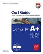
A workstation optimized for graphics or CAD/CAM (computer-aided drafting/computer-aided manufacturing) design needs the maximum performance available at the time of purchase. Because of the heavy demands that 3D CAD rendering or RAW photo editing place on the workstation, there is no place for cost-cutting when equipping this system. Don’t be surprised if the total cost of a new workstation optimized for these tasks rivals that of a server. Table 9-1 lists the major features needed for this type of computer along with examples and notes.

Although the A+ 220-901 exam objectives do not recommend specific motherboard configurations for these custom PC configurations, you should specify systems with adequate support for high-performance memory, processors, and video for the Graphic/CAD/CAM design workstation or Audio/Video editing workstation. A typical high-performance motherboard suitable as a foundation for these configurations is shown in Figure 9-1.

Figure 9-1 This high-performance system features a fast SSD using the M.2 form factor, DDR4 memory, and three PCIe video card slots.
Audio/Video Editing Workstation
An audio/video editing workstation has many component features in common with the Graphic/CAD/CAM Design Workstation detailed in the previous section. In fact, the recommendations in Table 9-2 for hard drives and displays are suitable for either type of workstation, and the CPU suggestions in Table 9-1 are also suitable for this type of workstation. Table 9-2 lists the major features needed for this type of computer and why they’re important.


Figure 9-2 This high-performance video card uses the NVIDIA TITAN Z GPU and is suitable for video and photo editing and gaming. Photo courtesy Gigabyte.
Virtualization Workstation
A virtualization workstation is intended to be a host for two or more operating systems running at the same time in separate virtual machines (VMs). To ensure adequate resources for each VM, this configuration (see Table 9-3) emphasizes RAM and CPU components.


Figure 9-3 The AMD FX-8350 has eight processor cores, supports AMD-V (hardware-assisted virtualization) and has a large amount of L2 and L3 cache as reported by CPU-Z.
Gaming PC

A gaming PC’s components are selected with just one objective in mind: provide the user with the computing firepower needed to defeat opponents as quickly as possible. The configuration covered in Table 9-4 is similar to others previously detailed but adds high-end cooling because these systems are frequently overclocked to enhance performance (at a cost in extra heat output).


Figure 9-5 A standard DDR3 desktop memory module compared to a high-performance DDR3 memory module with heat spreader.
Home Theater PC
The components in this section (see Table 9-5) emphasize compatibility with common home theater audio and video requirements that fit into the low-profile HTPC chassis designed to complement the rest of the home theater equipment.


Figure 9-6 This mini-ITX motherboard for home theater systems features an Intel processor with integrated graphics, HDMI A/V output, and a USB 3.0 port.
Standard Thick Client
Unlike the system configurations discussed earlier in this chapter, almost any computer you can purchase at a retail store qualifies as a standard thick client. The requirements are simple, as you can see from Table 9-6.

Thin Client
A thin client is the most basic type of system configuration, as Table 9-7 indicates.
Home Server PC
A home server PC configuration is designed to permit resource sharing, media streaming, and high-speed data retrieval from online or local storage, as detailed in Table 9-8.


Evaluating Onboard Components
From Tables 9-1 to 9-8, you can see that a PC can be customized in many different ways during initial build and setup. However, if you need to upgrade an existing system to optimize it for a particular task, it’s important to know what components are already installed. The following methods, Windows features, and third-party utilities can help you find out what’s “under the hood” of an existing system.
General System Information
![]() BIOS/UEFI setup—Some systems display information about installed hardware during startup, and you can also find out information such as RAID level, integrated ports, and other information by starting the BIOS setup program and moving through the screens. Be sure to discard changes when exiting.
BIOS/UEFI setup—Some systems display information about installed hardware during startup, and you can also find out information such as RAID level, integrated ports, and other information by starting the BIOS setup program and moving through the screens. Be sure to discard changes when exiting.
![]() System Information—A built-in Windows utility (MSInfo32.exe) that reports processor type and speed, BIOS/UEFI version and date, operating system information, memory size, components (including multimedia), and software environment. Report can be saved, printed, and searched. Use Run or Instant Desktop Search to start program.
System Information—A built-in Windows utility (MSInfo32.exe) that reports processor type and speed, BIOS/UEFI version and date, operating system information, memory size, components (including multimedia), and software environment. Report can be saved, printed, and searched. Use Run or Instant Desktop Search to start program.
![]() Device Manager—A built-in Windows utility that reports installed hard drives, USB ports, video cards, and other information. Available from System properties.
Device Manager—A built-in Windows utility that reports installed hard drives, USB ports, video cards, and other information. Available from System properties.
![]() Belarc System Advisor—A free (for personal use) ActiveX utility that displays hardware, software, and Windows security update information, including motherboard information. Available from www.belarc.com. See Figure 9-7 for a portion of a typical report.
Belarc System Advisor—A free (for personal use) ActiveX utility that displays hardware, software, and Windows security update information, including motherboard information. Available from www.belarc.com. See Figure 9-7 for a portion of a typical report.

Figure 9-7 The hardware portion of the Belarc System Advisor report on the author’s system provides details about the processor (CPU), motherboard, storage, and installed memory.
![]() SiSoftware Sandra—Displays extensive information about system hardware including expansion slots, memory, processor details, and much more. Available evaluation and commercial editions from www.sisoftware.net (see Figure 9-8).
SiSoftware Sandra—Displays extensive information about system hardware including expansion slots, memory, processor details, and much more. Available evaluation and commercial editions from www.sisoftware.net (see Figure 9-8).

Figure 9-8 A portion of the SiSoftware Sandra Lite report on the mainboard (motherboard) displays detailed information about the SuperSpeed USB (USB 3.0) and audio controllers onboard.
Note
For the most complete information about a system, use more than one reporting program.
Processor Information and Hardware-Assisted Virtualization Readiness
AMD, Intel, Microsoft, and third-party vendors provide various tools to help determine details about a processor, including whether a system supports hardware-assisted virtualization:
![]() AMD Virtualization™ Technology and Microsoft® Hyper-V™ System Compatibility Check Utility—Available from http://support.amd.com
AMD Virtualization™ Technology and Microsoft® Hyper-V™ System Compatibility Check Utility—Available from http://support.amd.com
![]() CPU-Z—Available from http://www.cpuid.com/
CPU-Z—Available from http://www.cpuid.com/
![]() Intel Processor Identification Utility—Available from www.intel.com
Intel Processor Identification Utility—Available from www.intel.com
![]() Microsoft Windows Hardware-Assisted Virtualization Detection Tool—Available from the Download Center at www.microsoft.com
Microsoft Windows Hardware-Assisted Virtualization Detection Tool—Available from the Download Center at www.microsoft.com
![]() Gibson Research Corporations SecurAble—Available from www.grc.com
Gibson Research Corporations SecurAble—Available from www.grc.com
Tip
Find direct links to these programs and a useful discussion at http://www.technorms.com/8208/check-if-processor-supports-virtualization.
For more information about processor virtualization, see “Client-Side Virtualization Overview,” p.958, Chapter 19, “Virtualization, Cloud Computing, and Network Services.”
Installing Power Supplies
Power supplies vary widely in features and ratings, and when building a custom configuration or updating a system to perform a specific task, the power supply is a critical factor in the success of that system.
The power supply is really misnamed: It is actually a power converter that changes high-voltage alternating current (AC) to low-voltage direct current (DC). There are lots of wire coils and other components inside the power supply that do the work, and during the conversion process, a great deal of heat is produced. Most power supplies include one or two fans to dissipate the heat created by the operation of the power supply; however, a few power supplies designed for silent operation use passive heat sink technology instead of fans. On power supplies that include fans, fans also help to cool the rest of the computer. Figure 9-9 shows a typical desktop computer’s power supply.

Power Supply Ratings
Power supply capacity is rated in watts, and the more watts a power supply provides, the more devices it can safely power.
You can use the label attached to the power supply, shown in Figure 9-10, to determine its wattage rating and see important safety reminders.

Figure 9-10 Typical power supply labels. Many, but not all, power supplies now include some level of 80 PLUS certification.
A power supply with two separate +12V rails is a dual rail design. Some high-performance power supplies feature more than two +12V outputs, such as the 650-watt model shown in Figure 9-10. Another term for two or more +12V outputs is split rail.
Power supplies with two or more separate +12V power sources are common today to provide adequate power for CPUs (which use voltage regulators on the motherboard or in the CPU itself to reduce +12V power to the power level needed) and other devices such as PCIe video cards, fans, and drives). Add the values of each +12V rail together to get the total +12V output in amps.
Typically, power supplies in recent tower-case (upright case) machines use 500-watt or larger power supplies, reflecting the greater number of drives and cards that can be installed in these computers. Power supplies used in slimline desktop computers have typical ratings of around 220-300 watts. The power supply rating is found on the top or side of the power supply, along with safety rating information and amperage levels produced by the power supply’s different DC outputs.
How can you tell whether a power supply meets minimum safety standards? Look for the appropriate safety certification mark for your country or locale. For example, in the U.S. and Canada, the backward UR logo is used to indicate the power supply has the UL and UL Canada safety certifications as a component (the familiar circled UL logo is used for finished products only). Both power supplies shown in Figure 9-10 meet U.S. and other nations’ safety standards.
Caution
Power supplies that do not bear the UL or other certification marks should not be used, as their safety is unknown. For a visual guide to electrical and other safety certification marks in use around the world, visit the Standard Certification Marks page at www.technick.net/public/code/cp_dpage.php?aiocp_dp=guide_safetymarks.
Use the following methods to determine the wattage rating needed for a replacement power supply:
![]() Whip out your calculator and add up the wattage ratings for everything connected to your computer that uses the power supply, including the motherboard, processor, memory, cards, drives, and bus-powered USB devices. If the total wattage used exceeds 70 percent of the wattage rating of your power supply, you should upgrade to a larger power supply. Check the vendor spec sheets for wattage ratings.
Whip out your calculator and add up the wattage ratings for everything connected to your computer that uses the power supply, including the motherboard, processor, memory, cards, drives, and bus-powered USB devices. If the total wattage used exceeds 70 percent of the wattage rating of your power supply, you should upgrade to a larger power supply. Check the vendor spec sheets for wattage ratings.
![]() If you have amperage ratings instead of wattage ratings, multiply the amperage by the volts to determine wattage and then start adding. If a device uses two or three different voltage levels, be sure to carry out this calculation for each voltage level and add up the figures to determine the wattage requirement for the device. Review Figure 9-10 and the “Wattage Versus Amperage” sidebar earlier in this chapter for a reminder of the importance of +12V amperage.
If you have amperage ratings instead of wattage ratings, multiply the amperage by the volts to determine wattage and then start adding. If a device uses two or three different voltage levels, be sure to carry out this calculation for each voltage level and add up the figures to determine the wattage requirement for the device. Review Figure 9-10 and the “Wattage Versus Amperage” sidebar earlier in this chapter for a reminder of the importance of +12V amperage.
![]() Use an interactive power supply sizing tool, such as the calculators provided by eXtreme Outervision (www.extreme.outervision.com) or MSI (https://us.msi.com/power-supply-calculator/).
Use an interactive power supply sizing tool, such as the calculators provided by eXtreme Outervision (www.extreme.outervision.com) or MSI (https://us.msi.com/power-supply-calculator/).
Table 9-9 provides calculations for typical compact desktop and high-performance desktop systems, based on the eXtreme Outervision online calculator.

The 80 PLUS certification standard is an industry standard for evaluating power supply efficiency. 80 PLUS certified power supplies achieve 80 percent efficiency at up to 100 percent of rated load. The use of power supplies with 80 PLUS certification is assumed in Table 9-9. Higher standards (80 PLUS Bronze, Silver, Gold, and Platinum) achieve up to 89 percent efficiency at 100 percent of rated load on 115V power and up to 91 percent on 230V power. For more information, see the Ecova Plug Load Solutions website at http://www.plugloadsolutions.com/. For non-80 PLUS power supplies, assume 70 percent efficiency.
Multivoltage Power Supplies
Most power supplies are designed to handle two different voltage ranges:
![]() 110–120V/60Hz
110–120V/60Hz
![]() 220–240V/50Hz
220–240V/50Hz
Power supplies that support these ranges are known as dual voltage power supplies. Standard North American power is now 115–120V/60Hz-cycle AC (the previous standard was 110V). The power used in European and Asian countries is typically 230–240V/50Hz AC (previously 220V).
Some older power supplies have a slider switch with two markings: 115 (for North American 110–120V/60HzAC) and 230 (for European and Asian 220–240V/50Hz AC). Figure 9-11 shows a slider switch set for correct North American voltage. If a power supply is set to the wrong input voltage, the system will not work. Setting a power supply for 230V with 110–120V current is harmless; however, feeding 220–240V into a power supply set for 115V will destroy the power supply and possibly other onboard hardware.

Figure 9-11 An older power supply’s sliding voltage switch set for correct North American voltage (115V). Slide it to 230V for use in Europe and Asia.
Note that most recent power supplies for desktop and notebook computers can automatically determine the correct voltage level and cycle rate. These are referred to as autoswitching power supplies and lack the voltage/cycle selection switch shown in Figure 9-11.
The on/off switch shown in Figure 9-11 controls the flow of current into the power supply. It is not the system power switch, which is located on the front or top of desktop systems and is connected to the motherboard. When you press the system power switch, the motherboard signals the power supply to provide power.
Caution
Unless the power supply is disconnected from AC current or is turned off, a small amount of power can still be flowing through the system even when it is not running. Do not install or remove components or perform other types of service to the inside of a PC unless you disconnect the AC power cord or turn off the power supply. Wait a few seconds afterward to ensure that the power is completely off. Some desktop motherboards have indicator lights that turn off when the power has completely drained from the system.
Power Supply Form Factors and Connectors
When you shop for a power supply, you also need to make sure it can connect to your motherboard. There are two major types of power connectors on motherboards:
![]() 20-pin, used by older motherboards in the ATX family
20-pin, used by older motherboards in the ATX family
![]() 24-pin, used by recent ATX/microATX/mini-ITX motherboards requiring the ATX12V 2.2 power supply standard
24-pin, used by recent ATX/microATX/mini-ITX motherboards requiring the ATX12V 2.2 power supply standard
Some high-wattage power supplies with 20-pin connectors might also include a 20-pin to 24-pin adapter. Some 24-pin power supplies include a split connector to support either 24-pin or 20-pin motherboard power connectors (refer to Figure 9-13).
Most motherboards use power supplies that feature several additional connectors to supply added power, as follows (see Figure 9-12):
![]() The four-wire square ATX12V connector provides additional 12V power to the motherboard; this connector is sometimes referred to as a “P4” or “Pentium 4” connector.
The four-wire square ATX12V connector provides additional 12V power to the motherboard; this connector is sometimes referred to as a “P4” or “Pentium 4” connector.
![]() Most recent power supplies use the 4/8 pin +12V (EPS12V) connector (see Figure 9-14) instead of the ATX12V power connector. The EPS12V lead is split into two four-wire square connectors to be compatible with motherboards that use either ATX12V or EPS12V power leads.
Most recent power supplies use the 4/8 pin +12V (EPS12V) connector (see Figure 9-14) instead of the ATX12V power connector. The EPS12V lead is split into two four-wire square connectors to be compatible with motherboards that use either ATX12V or EPS12V power leads.
![]() Some very old motherboards use a six-wire AUX connector to provide additional power.
Some very old motherboards use a six-wire AUX connector to provide additional power.

Figure 9-12 20-pin ATX and 24-pin ATX power connectors compared to four-pin ATX12V and six-wire AUX power connectors.
Figure 9-13 shows both sides of a convertible 24-pin/20-pin ATX power supply connector. For a complete pinout, see Figure 13-12.

Figure 9-13 Both sides of a 24-pin ATX power supply cable (also compatible with 20-pin motherboards)
The power supply also powers various peripherals, such as the following:
![]() Older (PATA and early SATA) hard disks, CD and DVD optical drives, and case fans that do not plug into the motherboard use a 4-pin Molex power connector.
Older (PATA and early SATA) hard disks, CD and DVD optical drives, and case fans that do not plug into the motherboard use a 4-pin Molex power connector.
![]() 3.5-inch floppy drives use a 4-pin Berg power connector.
3.5-inch floppy drives use a 4-pin Berg power connector.
![]() Serial ATA (SATA) hard disks use an L-shaped 15-pin thinline power connector.
Serial ATA (SATA) hard disks use an L-shaped 15-pin thinline power connector.
![]() High-performance PCI Express x16 video cards that require additional 12V power use a PCI Express 6-pin or 8-pin power cable (PCIe 6/8-pin).
High-performance PCI Express x16 video cards that require additional 12V power use a PCI Express 6-pin or 8-pin power cable (PCIe 6/8-pin).
Figure 9-14 illustrates these power connectors as well as the EPS12V motherboard power connector.

Table 9-10 lists the power levels carried by each connector type.

If your power supply doesn’t have enough connectors, you can add Y-splitters to divide one power lead into two, but these can short out and can also reduce your power supply’s efficiency. You can also convert a standard Molex connector into an SATA or Berg floppy drive power connector with the appropriate adapter.
Standard power supply wires are color-coded thus:
Red: +5V
Yellow: +12V
Orange: +3.3V
Black: Ground (earth)
Purple: +5V (standby)
Green: PS-On
Gray: Power good
White: No connection (24-pin); -5V (20-pin)
Blue: -12V
Some power supplies (see Figure 9-15) use modular connections so that you can customize the power supply connections needed for your hardware.

Figure 9-15 A modular power supply includes cables you can attach to customize support for your system’s needs.
Caution
Many recent and older Dell desktop computers use proprietary versions of the 20-pin or 24-pin ATX power supply connectors. Dell’s versions use a different pinout that routes voltages to different wires than in standard power supplies. Consequently, if you plug a standard power supply into a Dell PC that uses the proprietary version, or use a regular motherboard as an upgrade for a model that has the proprietary power supply, stand by for smoke and fire! You can look up your Dell computer model or power supply number at www.atxpowersupplies.com/power-supply-cross-reference.php to see whether you can use a standard or proprietary-pinout power supply.
If your wattage calculations or your tests agree that it’s time to replace the power supply, make sure the replacement meets the following criteria:
![]() Has the same power supply connectors and the same pinout as the original.
Has the same power supply connectors and the same pinout as the original.
![]() Has the same form factor (shape, size, and switch location).
Has the same form factor (shape, size, and switch location).
![]() Has the same or higher wattage rating; a higher wattage rating is highly desirable.
Has the same or higher wattage rating; a higher wattage rating is highly desirable.
![]() Supports any special features required by your CPU, video card, and motherboard, such as SLI support (support for PCIe connectors to power two or more high-performance PCIe video cards), high levels of +12V power (ATX12V v2.2 4-pin or EPS12V 8-pin power connectors), and so on.
Supports any special features required by your CPU, video card, and motherboard, such as SLI support (support for PCIe connectors to power two or more high-performance PCIe video cards), high levels of +12V power (ATX12V v2.2 4-pin or EPS12V 8-pin power connectors), and so on.
Tip
To ensure form factor connector compatibility, consider removing the old power supply and taking it with you if you plan to buy a replacement at retail. If you are buying a replacement online, measure the dimensions of your existing power supply to ensure that a new one will fit properly in the system. So-called “EPX” power supplies are longer than ATX power supplies, and won’t fit into smaller cases.
Removing and Replacing the Power Supply
Installing a new power supply is one of the easier repairs to make. You don’t need to fiddle with driver CDs or Windows Update to get the new one working. But, you do need to be fairly handy with a screwdriver or nut driver.
Note
Follow these recommendations to make power supply replacement as safe as possible:
![]() Disconnect power before repairing PC
Disconnect power before repairing PC
![]() Remove jewelry before repairing PC
Remove jewelry before repairing PC
![]() Be prepared for electrical fires
Be prepared for electrical fires
![]() Wear safety goggles
Wear safety goggles
To learn more about these precautions, see “Personal Safety,” p.891, Chapter 17, “Operational Procedures.”
Typical power supplies are held in place by several screws that attach the power supply to the rear panel of the computer. The power supply also is supported by a shelf inside the case and screws can secure the power supply to that shelf. To remove a power supply, follow these steps:
Step 1. Power down the computer. If the power supply has an on/off switch, turn it off as well.
Step 2. Disconnect the AC power cord from the computer.
Step 3. Open the case to expose the power supply, which might be as simple as removing the cover on a desktop unit, or as involved as removing both side panels, front bezel, and case lid on a tower PC. Consult the documentation that came with your computer to determine how to expose the power supply for removal.
Step 4. Disconnect the existing power supply from the motherboard (see Figure 9-16). The catch securing the power supply connector must be released to permit the connector to be removed.

Step 5. Disconnect all other power supply leads to the motherboard (fan monitors, ATX12V, EPS12V, AUX).
Step 6. Disconnect the power supply from all drives and add-on cards (see Figure 9-17).

Step 7. Disconnect the power supply from all fans.
Step 8. Remove the power supply screws from the rear of the computer case (see Figure 9-18).

Step 9. Remove any screws holding the power supply in place inside the case. (Your PC might not use these additional screws.)
Step 10. Lift or slide the power supply out of the case.
Before installing the replacement power supply, compare it to the original, making sure the form factor, motherboard power connectors, and switch position match the original. If the new power supply has a fan on top (as well as the typical rear-mounted fan), make sure the fan faces the inside of the case.
To install the replacement power supply, follow these steps:
Step 1. Lift or slide the power supply into the case.
Step 2. Attach the power supply to the shelf with screws (if required).
Step 3. Slide the power supply to the rear of the computer case; line up the holes in the unit carefully with the holes in the outside of the case.
Step 4. Connect the power supply to all fans, drives, add-on cards, and motherboard.
Step 5. Check the voltage setting on the power supply. Change it to the correct voltage for your location if necessary.
Step 6. Connect the AC power cord to the new power supply. Turn on the power supply
Step 7. Start the computer.
Step 8. Start the system normally to verify correct operation, and then run the normal shutdown procedure for the operating system. If necessary, turn off the system with the front power switch only.
Step 9. Close the case and secure it.
Installing and Configuring Input, Output, and I/O Devices
Custom PC configurations might also require the installation of input, output, and I/O devices. The following sections discuss the installation processes for these devices.
Note
Printer installation is covered in Chapter 10. Video card installation is covered in Chapter 5. Video card connections to displays are covered in Chapter 8.
Mouse
Windows, OS X, and Linux include mouse (pointing device) drivers. To install a USB mouse, simply plug it in, and the operating system installs the drivers needed. Mice are part of the human interface device (HID) device category, and Windows installs HID drivers after the mouse is connected.
To install a wireless mouse, plug the receiver into a USB port and follow the directions to pair up the mouse and receiver. Receivers that can control multiple devices, such as Logitech’s Unifying receiver, might require you to install additional software to enable pairing of multiple devices with a single receiver.
Mouse alternatives, such as touchscreens, trackballs, or touch pads, are considered mouse devices because they install and are configured the same way.
If a mouse has special buttons for gaming, install drivers for the mouse from the vendor. These can be installed after the mouse has been connected.
Note
Some systems running Windows and Linux have PS/2 mouse and/or keyboard ports. To install a PS/2 mouse or keyboard, be sure to shut down the system and remove power before connecting the mouse or keyboard. PS/2 devices, unlike USB devices, are not hot-swappable devices.
If the mouse uses Bluetooth, it needs to be paired with the computer’s Bluetooth receiver.
Pairing a Bluetooth Mouse (Windows)
To pair a Bluetooth mouse computer from the desktop:
Step 1. Click the Bluetooth icon in the taskbar.
Step 2. Click or tap Open Settings.
Step 3. Enable Discovery.
Step 4. Enable Allow Bluetooth Devices to Connect to This Computer (see Figure 9-19).

Step 5. Open the Bluetooth icon in the Taskbar and click or tap Add a Device.
Step 6. Press the Connect button on the mouse.
Step 7. Select the mouse from the list of Bluetooth devices and click Next (see Figure 9-20).

Step 8. After the mouse is detected and the drivers have been installed, click Close.
Step 9. To prevent connections from unauthorized Bluetooth devices, disable discovery until the next time you want to add a Bluetooth device.
Keyboard
Windows, OS X, and Linux include keyboard drivers. To install a USB keyboard, simply plug it in, and the operating system installs the drivers needed. Keyboards are part of the human interface device (HID) device category and Windows installs HID drivers after the keyboard is connected.
To install a wireless keyboard, plug the receiver into a USB port, and follow the directions to pair up the keyboard and receiver.
If a keyboard has special buttons for multimedia or gaming, install drivers for the keyboard from the vendor. These can be installed after the keyboard has been connected.
If the keyboard uses Bluetooth, it needs to be paired with the computer’s Bluetooth receiver. The instructions for pairing a Bluetooth keyboard are similar to those for pairing a mouse, except that the user is prompted to enter a code on the keyboard during the pairing process.
![]() Almost all multifunction print/scan/fax/copy devices include a flatbed scanner with resolutions up to 2400 dpi. Most of these also include a sheet feeder for easier scanning of multiple pages.
Almost all multifunction print/scan/fax/copy devices include a flatbed scanner with resolutions up to 2400 dpi. Most of these also include a sheet feeder for easier scanning of multiple pages.
![]() Scanners made for photos typically support resolutions up to 4800 dpi or greater. Some include a diffuser or clear glass lid light source with negative or transparency holders for use in scanning negatives and slides. Some of these can scan negatives as large as 8×10 inches.
Scanners made for photos typically support resolutions up to 4800 dpi or greater. Some include a diffuser or clear glass lid light source with negative or transparency holders for use in scanning negatives and slides. Some of these can scan negatives as large as 8×10 inches.
![]() Scanners made for travel scan a single sheet at a time and might weigh as little as one pound (about a half-kilogram). These typically have resolutions up to 600 dpi.
Scanners made for travel scan a single sheet at a time and might weigh as little as one pound (about a half-kilogram). These typically have resolutions up to 600 dpi.
All of these scanners plug into a USB port (some can also use Wi-Fi). Drivers are typically installed before the scanner is connected. Drivers are available for Windows and OS X, and portable models also support Android and iOS. Some scanner vendors also provide Linux drivers.
Software included with a scanner varies, but scanners for Windows and OS X typically include page-recognition software and some type of photo editing or organizing app.
Barcode Reader
Barcode (bar code) readers are used in a variety of point-of-sale retail, library, industrial, medical, and other environments to track inventory.
Barcode readers use one of the following technologies:
![]() Pen-based readers use a pen-shaped device that includes a light source and photo diode in the tip. The point of the pen is dragged across the bar code to read the varying thicknesses and positions of the bars in the bar code and translate them into a digitized code that is transmitted to the point-of-sale (POS) or inventory system.
Pen-based readers use a pen-shaped device that includes a light source and photo diode in the tip. The point of the pen is dragged across the bar code to read the varying thicknesses and positions of the bars in the bar code and translate them into a digitized code that is transmitted to the point-of-sale (POS) or inventory system.
![]() Laser scanners are commonly used in grocery and mass-market stores. They use a horizontal-mounted or vertical-mounted prism or mirror and laser beam protected by a transparent glass cover to read bar codes.
Laser scanners are commonly used in grocery and mass-market stores. They use a horizontal-mounted or vertical-mounted prism or mirror and laser beam protected by a transparent glass cover to read bar codes.
![]() CCD or CMOS readers use a hand-held gun-shaped device to hold an array of light sensors mounted in a row. The reader emits light that is reflected off the bar code and is detected by the light sensors.
CCD or CMOS readers use a hand-held gun-shaped device to hold an array of light sensors mounted in a row. The reader emits light that is reflected off the bar code and is detected by the light sensors.
![]() Camera-based readers contain many rows of CCD sensors that generate an image of the sensor that is processed to decode the barcode information.
Camera-based readers contain many rows of CCD sensors that generate an image of the sensor that is processed to decode the barcode information.
Wired bar code readers typically interface through the USB port. See the documentation for the reader to determine whether you install the driver before or after connecting the reader. Many bar code readers use Bluetooth to make a wireless connection between the reader and the computer or other data-acquisition device. In such cases, you need a Bluetooth receiver in your PC and the device needs to be paired with the computer or POS system.
Biometric Devices
Biometric devices measure a bodily characteristic to identify a trusted user. The most common biometric device for PCs is a fingerprint reader. Some laptops have fingerprint readers, but one can be added via the USB port if needed.
When a fingerprint reader is attached to the USB port on a Windows computer, drivers are installed automatically. However, a fingerprint reader app must also be installed and the user’s fingerprints must be read and added to the authentication modes used by the operating system before a user can log in by using fingerprints.
Some computers running OS X have built-in (embedded) fingerprint readers, but current versions of OS X do not support third-party fingerprint readers.
To use a fingerprint reader (USB or embedded) with a Linux computer, be sure to check compatibility. The Fprint utility is designed to help Linux use fingerprint readers. For more information, see https://wiki.archlinux.org/index.php/Fprint. To see how to install specific readers in a specific Linux distribution, search for the distribution version and specify fingerprint reader in the search.
Iris-based readers are being used for access control, banking, and other applications where positive identification is needed. These devices often use Power over Ethernet to enable use at some distance from the server hosting the identification databases.
Game Pads and Joysticks
Game pads and joysticks are popular game control devices that plug into a computer’s USB port. In most cases, Windows installs compatible drivers automatically as soon as a game pad or joystick is plugged in. However, if the controller does not work, it might be necessary to manually select the correct driver from the controller’s properties sheet in Device Manager. If the controller uses Bluetooth, pair it with the receiver in your system.
OS X has varied support for game pads and joysticks. With some controllers, you can install vendor-supplied OS X drivers. If the controller uses Bluetooth, pair it with your system. Otherwise, use a driver package such as Joystick Mapper (http://joystickmapper.com/), Tattiebogle driver (Xbox controllers; see http://tattiebogle.net/index.php/ProjectRoot/Xbox360Controller), GamePad Companion (Apple App Store), USB Overdrive, DarwiinRemote (Wii controller—https://sourceforge.net/projects/darwiin-remote/) and Wjoy driver (Wii controller: https://github.com/alxn1/wjoy). For more information, see http://www.cnet.com/how-to/how-to-connect-game-controllers-to-your-mac/.
Game pads and joysticks on Linux are supported by the “Joystick” interface and the newer “evdev” interface. If a specific driver is not available, go to https://wiki.archlinux.org/index.php/Gamepad to learn how to configure your controller.
Digitizer
A digitizer translates touch into a command recognized by a computing device. Digitizers can be retrofitted to a PC in two ways:
![]() Drawing tablets from companies such as Wacom and Turcom plug into the USB port and include a pressure-sensitive pen. After installing drivers, you can draw with your finger or the pen in graphics programs such as Adobe Photoshop or any app that accepts mouse input. Without drivers, touch pads emulate mice.
Drawing tablets from companies such as Wacom and Turcom plug into the USB port and include a pressure-sensitive pen. After installing drivers, you can draw with your finger or the pen in graphics programs such as Adobe Photoshop or any app that accepts mouse input. Without drivers, touch pads emulate mice.
![]() Touch screens, which include a digitizer layer to register touch, have long been available for use in industry and POS systems, but are now common in all-in-one computers, laptops, and as displays for use with non-touch consumer PCs. For details, see “Touch Screen,” later in this chapter.
Touch screens, which include a digitizer layer to register touch, have long been available for use in industry and POS systems, but are now common in all-in-one computers, laptops, and as displays for use with non-touch consumer PCs. For details, see “Touch Screen,” later in this chapter.
Motion Sensor
A motion sensor connected to a computer is typically used for gaming, computer control, and video chatting. Some representative products include:
![]() Leap Motion sensor (www.leapmotion.com)—uses a sensor that is placed in front of the computer to detect motion and depth; also supports virtual reality (VR) headsets.
Leap Motion sensor (www.leapmotion.com)—uses a sensor that is placed in front of the computer to detect motion and depth; also supports virtual reality (VR) headsets.
![]() Microsoft Kinect (www.xbox.com/en-US/xbox-one/accessories/kinect-for-xbox-one)—uses a motion and depth-detection camera.
Microsoft Kinect (www.xbox.com/en-US/xbox-one/accessories/kinect-for-xbox-one)—uses a motion and depth-detection camera.
![]() Creative Senz3D (http://us.creative.com/p/web-cameras/creative-senz3d)—combines depth and gesture recognition with a 720p webcam.
Creative Senz3D (http://us.creative.com/p/web-cameras/creative-senz3d)—combines depth and gesture recognition with a 720p webcam.
To install a USB-based motion sensor:
Step 1. Connect the sensor to the recommended USB port. With some sensors being used with VR apps, you might need to use USB 3.0 ports because of their much greater speed.
Step 2. Turn on the unit.
Step 3. Install software from the vendor.
Step 4. Download apps compatible with the device.
Touch Pads
Touch pads (also known as touchpads, trackpads, or track pads) are built into almost all laptops and the keyboards on many tablets. Touch pads are also available as standalone devices or integrated into keyboards. Touch pads and keyboards that include touch pads plug in through the USB port, and are recognized as mice by Windows’ built-in drivers.
If the touch pad or keyboard with integrated touch pad is wireless, it is normally recognized automatically. If the touch pad or keyboard has additional keys or buttons, it might be necessary to install proprietary drivers to enable the additional keys or buttons. Proprietary drivers are also necessary to enable multi-touch gestures (using two or more fingers).
Smart Card Readers
A smart card reader plugs into a USB port. Once a smart card reader has been installed, it works the same as a built-in smart card reader for controlling access to corporate networks or other restricted resources.
Smart card readers are supported by Windows, OS X, and popular Linux distributions. Drivers are typically installed automatically when the smart card reader is connected.
Digital Cameras
Digital cameras have almost completely replaced film cameras for both amateur and professional photography. They use CMOS or CCD image sensors to record images onto internal or card-based flash memory form factors. For casual snapshots and sharing on social media such as Facebook, Twitter, and Instagram, the integrated cameras in smartphones have largely replaced point-and-shoot cameras.
Digital cameras and smartphones transfer images to computers for emailing, printing, or storage via either flash memory card readers, direct USB port connections, or through wireless connections.
Installing a Digital Camera
To connect a digital camera to your PC, follow these steps:
Step 1. Connect the USB cable provided with the camera to the camera’s USB port and the computer’s USB port.
Step 2. Turn on the camera.
Step 3. If the camera is not recognized after a few seconds, select the picture playback option on the camera. If the camera is still not recognized, install drivers for the camera.
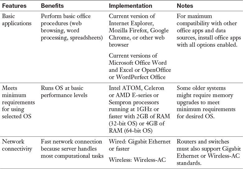
Depending on the version of Windows and the camera’s capabilities, the camera might be assigned a drive letter, show up as an imaging device, or display a menu with options for working with photos (see Figure 9-21). The contents of a Windows AutoPlay menu vary according to the photo-handling apps installed.
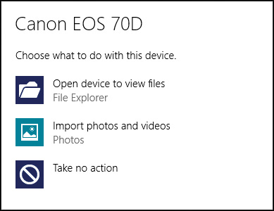
Figure 9-21 Windows 8.1 displays an AutoPlay menu including Photos (Windows 8/8.1/10 Modern UI) and File Explorer when a digital camera is connected.
With OS X, open Image Capture and select the camera, then select the pictures to import. For details, see https://support.apple.com/kb/PH17894.
With Linux, the photo import options vary by distribution. Some popular choices include digiKam (for KDE), gThumb (for GNOME), and Rapid Photo Downloader (http://www.damonlynch.net/rapid/).
If you are configuring a computer running Windows Vista or 7 to work with RAW photos, you might need to add the appropriate RAW codec (coder-decoder) program to the computer so image thumbnails are visible in Windows Explorer. RAW codecs are available from the camera vendor, from Microsoft, or from third-party vendors. The Microsoft Camera Codec Pack for 32-bit and 64-bit versions of Windows Vista and Windows 7 is available from the Microsoft Download Center. Commercial codecs for use with Windows are available from fastpictureviewer.com, Ardfry.com, and others.
Windows 8/8.1/10 include RAW codec support via Windows Update. OS X also includes RAW codec support. Some photo import apps for Linux, such as digiKam, also support RAW photos.
Microphone
A microphone plugs into the 1/8-inch (3.5mm) mini-jack microphone jack on a sound card or integrated motherboard audio. The most common microphones used on PCs include those built in to headsets or those that use a stand.
In Windows, microphone volume is controlled by the Windows Sound applet’s mixer control. Open the Recording tab to adjust volume, to mute or unmute the microphone, or to adjust microphone boost.
In OS X, open System Preferences > Sound > Input to find the microphone volume control. In Linux, open System Settings > Sound >Input to find the microphone volume control.
Note
The microphone jack is monaural, whereas the line-in jack supports stereo. Be sure to use the line-in jack to record from a stereo audio source.
Installing and Configuring a Microphone
To install a microphone on a PC with a sound card or integrated audio, follow this procedure:
Step 1. Connect the microphone into the microphone jack, which is marked with a pink ring or a microphone icon.
Step 2. Audio hardware that supports AC’97 version 2.3 audio or HD Audio standards might pop up a dialog that asks you to confirm the device you have plugged into the microphone jack. Select Microphone from the list of devices.
Step 3. If the microphone has an on-off switch, make sure the microphone is turned on.
To verify that the microphone is working in Windows:
Step 1. Open the Sounds icon in Control Panel.
Step 2. Click the Recording tab.
Step 3. Make sure the microphone you installed is enabled and selected as the default device.
Step 4. Click Configure.
Step 5. From the Speech Recognition menu that opens, click Set Up Microphone.
Step 6. Select the microphone type and click Next.
Step 7. Adjust the microphone position and click Next.
Step 8. Read the onscreen text when prompted and click Next when finished.
Step 9. Click Finish. Close the Speech Recognition dialog to return to the Sounds dialog.
Tip
If the volume displayed in Step 8 is too low or too high, click Properties from the Sounds dialog. Click the Levels tab, adjust Microphone boost to the midpoint (10.0db), and retry Steps 4-9. If the volume is still too low or too high, adjust the volume on the Levels tab.
Webcam
A webcam is a simple digital camera capable of taking video or still images for transmission over the Internet. Unlike digital cameras, webcams don’t include storage capabilities.
Virtually all webcams plug into a USB port or use wireless technology. Webcams are generally used in live chat situations, such as with Skype, AOL Instant Messenger, or other IM clients. They offer resolutions ranging from sub-VGA to full 1080p HD. Some offer autofocus and zoom features for better image clarity, and most have built-in microphones.
Installing and Configuring a Webcam
Before connecting the webcam, you typically need to install driver and configuration software. Obtain the most up-to-date drivers from the vendor’s website.
After the webcam is installed, use its setup menu to adjust white balance, exposure, gain, and other options (see Figure 9-22). If you plan to use the webcam’s microphone, disable other microphones in your computer’s audio mixer application.

Before using the webcam for IM or phone calls, make sure the application is configured to use the webcam.
Camcorder
A camcorder is used to record video. When a camcorder is connected via the USB port on a computer running Windows 8/8.1/10, Windows displays an AutoPlay app with options for importing or viewing the video files. Files stored in an HD Camcorder’s onboard or flash card memory can be imported directly without conversion. With Windows 7, it might be necessary to install Windows Live Essentials to import video (get it from http://windows.microsoft.com/en-us/windows/essentials).
With older DV camcorders (these used tape for video storage), selecting the Import Video option from AutoPlay brings up these choices: create an Audio Video Interleaved (single file), also known as an AVI file; create a Windows Media Video File (single file) or Windows Media Video (one file per scene). See http://windows.microsoft.com/en-US/windows-vista/Import-live-video-from-a-DV-camera for details.
With OS X, use iMovie to import your video. See https://support.apple.com/en-us/HT201734 for details.
With Linux, use an app such as Shotcut (www.shotcut.org, for many popular distros, also available from OS X 64-bit and Windows 64-bit), Kdenlive (www.kdenlive.org, for GNU/Linux), and others (see https://www.linux.com/news/top-3-linux-video-editors for additional choices).
Speakers
You can connect speakers to a computer in several ways:
![]() 3.5mm speaker mini-jack (see Figures 8-30 and 8-32, Chapter 8)
3.5mm speaker mini-jack (see Figures 8-30 and 8-32, Chapter 8)
![]() SPDIF digital audio port (see Figure 8-1 and 8-31, Chapter 8)
SPDIF digital audio port (see Figure 8-1 and 8-31, Chapter 8)
![]() Proprietary sound card header cable
Proprietary sound card header cable
![]() HDMI digital A/V port (see Figures 8-1 and 8-2, Chapter 8)
HDMI digital A/V port (see Figures 8-1 and 8-2, Chapter 8)
![]() USB surround audio external device
USB surround audio external device
The default setting for audio mixers is to use speakers connected to analog 3.5mm audio jacks. To use a digital speaker or audio output in Windows:
Step 1. Click or tap Hardware and Sound.
Step 2. In the Sound category, click or tap Manage Audio Devices.
Step 3. Click or tap a playback device on the Playback tab (see Figure 9-23).

Step 4. To make the selected device your default, click or tap Set Default.
Step 5. Click Apply and then click OK to use your new selection.
To make changes in OS X or Linux audio output, see “Configuring a Sound Card with OS X,” p. 129, Chapter 5, and “Configuring a Sound Card with Linux,” p. 129, Chapter 5.
Touch Screen
Touch screen displays are now available as upgrades to non-touch displays on Windows PCs. They differ from standard displays by incorporating a touch-sensitive digitizer layer that connects to the PC through a USB port, while the display functions connect to the PC’s video ports.
Touch screen displays are available from vendors such as Planar, ViewSonic, ASUS, Dell, Acer, HP, and others. For best compatibility with Windows 10, look for displays that support 10-point multitouch.
Linux has included multitouch display support for several years. See http://stackoverflow.com/questions/16976512/does-linux-support-multi-touch-screen for details. OS X supports multitouch in its touch pads, but display support is spotty.
Note
Multitouch refers to the use of two or more fingers on a touch screen or touch pad. 10-point multitouch is the most desirable, because it supports all fingers on both hands.
KVM
A keyboard-video-mouse (KVM) switch enables a single keyboard, display, and mouse to support two or more computers. KVM switches are popular in server rooms and are also useful in tech support environments.
The simplest KVM switch is a box with input connectors for USB or PS/2 mouse and keyboard and VGA or other display and two or more sets of cables leading to the corresponding I/O ports and video ports on the computers that will be hosted. Some KVM switches also support audio. With this type of KVM switch, a special key combination or a push button on the switch is used to switch between computers.
KVM switches for server rooms and data centers are known as local remote KVM and typically use CAT5 or higher-quality cables to run to special interface devices on each server.
To install a KVM switch:
Step 1. Shut down the computers and display.
Step 2. Connect the keyboard and mouse and other shared connectors (such as speakers) to the KVM switch.
Step 3. Connect the KVM switch to the computers.
Step 4. Start the computers.
Step 5. Install drivers if necessary.
Be sure to use the correct key combinations to switch between computers and to emulate other keyboards (for example, if a Windows keyboard is used with an OS X computer). In some situations, a firmware upgrade for the switch might be needed. Follow the instructions provided with the switch to perform a successful upgrade.
Smart TV
A smart TV combines a standard HDTV with support for streaming channels such as Amazon Prime, Netflix, YouTube, and others. After connecting a smart TV to power and to a cable or antenna source, you need to do the following to complete setup:
![]() Configure the Internet connection type (wired or wireless).
Configure the Internet connection type (wired or wireless).
![]() Obtain an IP address from the DHCP server on the network.
Obtain an IP address from the DHCP server on the network.
![]() Install any firmware updates available for the smart TV.
Install any firmware updates available for the smart TV.
![]() Select the streaming services the client wants to use.
Select the streaming services the client wants to use.
![]() For some streaming services, the client might need to sign up for a subscription or obtain an unlock code.
For some streaming services, the client might need to sign up for a subscription or obtain an unlock code.
After completing these tasks, test the smart TV by pressing the button(s) on the remote to switch to the streaming service desired.
Set-Top Box
The term set-top box refers to any device that enables a TV (HDTV, standard, or smart TV) to watch more types of programs or media. The most common set-top boxes today include:
![]() TV boxes (cable, satellite, fiber) used to unencrypt TV channels for viewing and recording TV. Some of these boxes include a PVR (personal video recorder).
TV boxes (cable, satellite, fiber) used to unencrypt TV channels for viewing and recording TV. Some of these boxes include a PVR (personal video recorder).
![]() Streaming media devices such as Roku, Amazon Fire TV, Apple TV, and so on.
Streaming media devices such as Roku, Amazon Fire TV, Apple TV, and so on.
![]() Blu-ray and DVD players.
Blu-ray and DVD players.
To connect a TV box directly to the TV:
Step 1. Connect the cable from the TV provider to the TV box.
Step 2. Connect the video output cable from the TV box to the TV. Use the highest-quality signal supported by both the TV and the TV box. (The best signal quality is HDMI, component is the next best.)
Step 3. Note the input used by the connection at the TV (Input 1, Input 2, and so on). To watch TV, this is the input the viewer must select.
Step 4. Turn on the TV, switch to the correct input on the TV, and verify proper operation.
To connect a streaming media device directly to the TV:
Step 1. Connect the cable from the streaming media device to the TV or to the receiver. Use the highest-quality signal supported by both the TV and the TV box. (The best signal quality is HDMI, component is the next best).
Step 2. Note the input used by the connection from the streaming media device or at the TV (Input 1, Input 2, and so on). To watch TV, this is the input the viewer must select.
Step 3. Turn on the TV, switch to the correct input on the TV, and set up the streaming media device. Select the correct network connection, select and install channels, and then set up any subscriptions.
Step 4. Verify proper operation.
To connect a Blu-ray or DVD player directly to the TV:
Step 1. Connect the cable from the streaming media device to the TV. Use the highest-quality signal supported by both the TV and the TV box. (The best signal quality is HDMI, component is the next best.)
Step 2. Note the input used by the connection from the Blu-ray or DVD player or receiver to the TV (Input 1, Input 2, and so on). To watch TV, this is the input the viewer must select.
Step 3. Turn on the TV and select the correct input.
Step 4. Turn on the player and insert a disc.
Step 5. Play the disc.
Tip
If a home theater receiver is being used, the cabling setup differs:
![]() If the receiver is an audio-only receiver (doesn’t distribute video signals), connect audio leads from the TV box, streaming media device, or Blu-ray/DVD drive to the receiver. Be sure to select the appropriate input and output on the receiver to hear audio.
If the receiver is an audio-only receiver (doesn’t distribute video signals), connect audio leads from the TV box, streaming media device, or Blu-ray/DVD drive to the receiver. Be sure to select the appropriate input and output on the receiver to hear audio.
![]() If the receiver also distributes video signals, connect audio and video leads from the TV box, streaming media device, or Blu-ray/DVD drive to the receiver. Connect a video lead from the receiver’s output jack to the TV. Be sure to select the appropriate input and output on the receiver and input on the TV to see video and play audio.
If the receiver also distributes video signals, connect audio and video leads from the TV box, streaming media device, or Blu-ray/DVD drive to the receiver. Connect a video lead from the receiver’s output jack to the TV. Be sure to select the appropriate input and output on the receiver and input on the TV to see video and play audio.
Installing a MIDI-Enabled Device
Although sounds cards and onboard audio can play MIDI files, MIDI interfacing must be available if you need to connect a MIDI-enabled device to a PC (a MIDI port is a five-pin DIN port). Some older sound cards had provision for a MIDI port adapter to be connected via the sound card’s joystick port. Newer sound cards use breakout boxes for MIDI ports, or you can attach a self-contained MIDI port via the USB port.
After ensuring that a MIDI port is available on a system, you can install a MIDI-enabled device. When connecting a MIDI-enabled device:
![]() Connect MIDI Out on the device to MIDI In on your PC’s MIDI interface.
Connect MIDI Out on the device to MIDI In on your PC’s MIDI interface.
![]() Connect MIDI Out on your PC’s MIDI interface to MIDI In on the device.
Connect MIDI Out on your PC’s MIDI interface to MIDI In on the device.
Display Types
A customized system configuration often requires selection of a display of a particular type, size, and resolution. There are five types of displays you need to understand for the A+ Certification exams:
![]() LCD (CCFL) displays
LCD (CCFL) displays
![]() LED (LCD-LED) displays
LED (LCD-LED) displays
![]() Plasma
Plasma
![]() Data projectors
Data projectors
![]() OLED
OLED
The following sections help you understand the common and unique features of each.
LCD Display Types
LCD displays use liquid crystal cells to polarize light passing through the display to create the image shown on the monitor. In color LCD displays, liquid crystal cells are grouped into three cells for each pixel: one each for red, green, and blue light.
LCD displays typically use one of two types of designs:
![]() Twisted nematic (TN)
Twisted nematic (TN)
![]() In-plane switching (IPS)
In-plane switching (IPS)
TN vs IPS
A TN display provides short response time (gray to gray [GTG] response time as fast as 2ms) and high brightness (especially when used with an LED backlight), making them highly suitable for gaming. They also draw less power and are less expensive than IPS displays. However, TN displays tend to lose contrast and display less accurate colors as the viewing angle increases.
An IPS display has a slower response time (5ms) and uses as much as 50% more power than a TN display with comparable resolution and screen size. However, an IPS display has a wider viewing angle without distorted colors or loss of contrast—up to 170 degrees or wider horizontally and vertically. IPS displays are better choices for presentations, graphics, or video editing.
![]() Fluorescent backlighting (CCFL)
Fluorescent backlighting (CCFL)
LCD-CCFL displays use a cold cathode fluorescent lamp (CCFL) as the lighting source. The CCFL develops ultraviolet light by discharging mercury into the lamp. The lamp’s inner fluorescent coating then allows for the emitting of visible light, which is sent to the actual display panel.
LCD-LED are frequently called LED displays because the CCFL has been replaced by one or more strips of LEDs along the edges of the display.
Plasma
Plasma displays are rarely found in computer monitors but are often found in televisions. Nowadays, computers can use many types of HDTVs as their display, including plasma, as long as the computer has the correct type of video port. Plasma displays use small cells that contain electrically charged ionized gases; effectively, these are fluorescent lamps. Plasma screens are known for brightness and low-luminance black level in comparison to LCD screens. This makes the plasma screen a higher energy consumer than LCD. It also prompted the LCD community to release LED-backlit LCD displays that were mentioned previously.
Data Projector
A data projector can be used in place of a primary display or can be used as a clone of the primary display to permit computer information and graphics to be displayed on a projection screen or a wall.
Data projectors use one of the following technologies:
![]() Liquid crystal display (LCD)
Liquid crystal display (LCD)
![]() Digital light processing (DLP)
Digital light processing (DLP)
LCD Projectors
LCD projectors use separate LCD panels for red, green, and blue light, and combine the separate images into a single RGB image for projection, using dichroic mirrors. A dichroic mirror reflects light in some wavelengths, while permitting light in other wavelengths to pass through. In Figure 9-24, red and blue dichroic mirrors are used to split the image into red, blue, and green wavelengths. After passing through the appropriate LCD, a dichroic combiner cube recombines the separate red, green, and blue images into a single RGB image for projection.

LCD projectors use a relatively hot projection lamp, so LCD projectors include cooling fans that run both during projector operation and after the projector is turned off to cool down the lamp.
DLP Projectors
All types of DLP displays, including projectors, use an array of tiny mirrors known as a digital micromirror device (DMD). Each tiny mirror in the DMD corresponds to a pixel, and the mirrors reflect light toward or away from the projector optics. DLP devices differ in the light source used. DLP devices such as HDTVs and digital theater projectors sometimes use a spinning wheel with red, green, and blue sections to add color data to light before it reaches the DMD. However, DLP data projectors use three different LED light sources (red, green, and blue) along with dichroic mirrors to provide color (see Figure 9-25). DLP technology dominates the ultra-compact pico and larger pocket projector categories.

OLED
OLED stands for organic light emitting diodes. OLED displays use organic semiconductor material usually in the form of polymers. Organic colored molecules are held in place between electrodes. A conductive layer made up of plastic molecules allows the organic colored molecules to emit light.
OLED display panels are currently used in some laptop displays as well as large screen HDTVs.
Video Display Settings and Features
Once a display is connected to your computer, it might need to be properly configured. The following sections discuss display settings issues and feature questions you might encounter in A+ Certification exams.
Note
Be sure you know where various tools and settings are located within the operating systems that are specified in the CompTIA A+ Exam objectives. For example, a performance-based question may ask you to change screen resolution settings in Windows.
Resolution
Display resolution is described as the amount of pixels (picture elements) on a screen. It is measured horizontally by vertically (HxV). The word resolution is somewhat of a misnomer and can also be referred to as pixel dimensions. Table 9-11 shows some of the typical resolutions used in Windows, Linux, and OS X. The more commonly used resolutions are in bold.

An LCD display has only one native resolution (the resolution it was designed to display); it must scale lower resolutions to fit the panel or, depending on the options configured in the video card driver, might use only a portion of the display when a lower resolution is selected. When a lower resolution is scaled, the display is less sharp than when the native resolution is used.
Some LCD displays use the standard 4:3 aspect ratio (1.33:1), but most use one of the widescreen aspect ratios: 16:9 aspect ratio (1.78:1) is the aspect ratio used by 720p and 1080i/1080p HDTVs; 16:10 aspect ratio (1.6:1) provides additional vertical pixels, making it better for productivity applications. LCD displays are currently available in sizes from 14 inches (diagonal measure) to 30 inches or larger.
To modify screen resolution do the following:
![]() In Windows 7/8/8.1/10—Right-click the desktop and select Screen Resolution. Use the Resolution vertical slider to select the desired pixel dimensions (see Figure 9-26). Click Apply, then Keep Changes on the confirmation dialog to keep the new resolution (otherwise, Windows reverts to the old one). Click OK when finished.
In Windows 7/8/8.1/10—Right-click the desktop and select Screen Resolution. Use the Resolution vertical slider to select the desired pixel dimensions (see Figure 9-26). Click Apply, then Keep Changes on the confirmation dialog to keep the new resolution (otherwise, Windows reverts to the old one). Click OK when finished.

Figure 9-26 The Screen Resolution window in Windows 8.1 controls display resolution, can detect monitors, and offers multiple monitor support.
![]() In Windows Vista—Right-click the desktop and select Personalize. Then click the Display Settings link. Toward the bottom left of the window is a box called Resolution. Use the slider to select the desired resolution.
In Windows Vista—Right-click the desktop and select Personalize. Then click the Display Settings link. Toward the bottom left of the window is a box called Resolution. Use the slider to select the desired resolution.
![]() In Linux—If you are using a GUI, open System Settings > Displays to select the desired resolution. After selecting a resolution, click Apply to use it. Figure 9-27 shows resolution options available in Ubuntu. If you are managing Linux from Terminal, use the
In Linux—If you are using a GUI, open System Settings > Displays to select the desired resolution. After selecting a resolution, click Apply to use it. Figure 9-27 shows resolution options available in Ubuntu. If you are managing Linux from Terminal, use the xrandr command to see and select from available resolutions. See http://www.ubuntugeek.com/how-change-display-resolution-settings-using-xrandr.html for details.

Figure 9-27 The Displays window in Ubuntu 14 workstation controls display resolution and offers multiple monitor support.
![]() In OS X—Open System Properties > Displays to select the desired resolution. To choose the native resolution for the display, click Default for display. To choose a different resolution, click Scaled and click the resolution desired (Figure 9-28).
In OS X—Open System Properties > Displays to select the desired resolution. To choose the native resolution for the display, click Default for display. To choose a different resolution, click Scaled and click the resolution desired (Figure 9-28).

Unless you need to select a lower resolution for specific purposes, you should select an LCD monitor’s native (recommended) resolution.
Note
To learn about configuring multiple displays, see “Multiple Monitor Misalignment/Orientation,” p.1098, Chapter 22.
Refresh Rates and Frame Rates
The vertical refresh rate refers to how quickly the monitor redraws the screen and is measured in hertz (Hz), or times per second. The refresh rate usually defaults to 60Hz.
Some displays offer an adjustable refresh rate. The vertical refresh in Windows 7/8/8.1/10 can be adjusted by accessing the Screen Resolution dialog, clicking Advanced Settings and then opening the Screen Refresh Rate menu. In Windows Vista, open the Display Properties sheet, click the Advanced button, and open the Screen Refresh Rate dialog.
If your monitor is listed as Default monitor rather than Plug and Play monitor or as a specific monitor model, you will not be able to choose flicker-free refresh rates. Install a driver provided by the vendor.
Caution
Selecting a refresh rate that exceeds the monitor’s specifications can damage the monitor or cause the monitor to display a blank screen or a “signal out of range” error. If you select a refresh rate that exceeds the monitor’s specifications, press the ESC (Escape) key on the keyboard to return to the previous setting.
In the context of display devices, frame rate refers to the frames per second (fps) speed of 3D rendering during games. The higher the frame rate the better, but any frame rate below 30fps makes a 3D game essentially unplayable. To improve frame rate, adjust the following, either with in-game menus or by using the 3D settings available for your GPU in its control center app:
![]() Quality setting—The lower the quality, the faster the frame rate. Depending on the driver settings or game options, you might be able to select which settings to reduce in quality, such as sampling, anti-aliasing, anisotropic filtering, and others.
Quality setting—The lower the quality, the faster the frame rate. Depending on the driver settings or game options, you might be able to select which settings to reduce in quality, such as sampling, anti-aliasing, anisotropic filtering, and others.
![]() Display resolution—The lower the resolution, the faster the frame rate.
Display resolution—The lower the resolution, the faster the frame rate.
Some games feature an option to display frame rate during game play. Otherwise, I recommend Fraps (fraps.com). Fraps can benchmark games, capture screens, or perform real-time video capture on both DirectX and OpenGL games played on Windows.
Note
For more information about adjusting 3D gaming settings, see Chapter 13, “Fixing Slow 3D Gaming,” in my book The PC and Gadget Help Desk (http://www.quepublishing.com/store/pc-and-gadget-help-desk-a-do-it-yourself-guide-to-troubleshooting-9780789753458).
Analog versus Digital Displays
Although most desktop computers continue to include a VGA port, this analog display connector, introduced in 1987, is definitely a legacy port. When shopping for a display, you should consider displays that support one or more of the following digital display connectors:
![]() DVI-D
DVI-D
![]() HDMI
HDMI
![]() DisplayPort
DisplayPort
Many LCD displays and projectors also include a VGA port, but using an analog display connector requires a digital-to-analog conversion in the computer and an analog-to-digital conversion at the display or projector, which can introduce display quality problems, limits resolution, and prevents the playback of protected digital content (Blu-ray, premium movie channels, and so on) at full resolution. To make sure you can play back protected digital content with your computer, make sure the video card and display/projector support HDCP (high-bandwidth digital copy protection).
To learn more about video cards and ports, see “Video,” p.273, Chapter 8.
Brightness/Lumens
The brightness of an LCD display is measured in candelas per square meter (cd/m2), sometimes referred to as “nits.” The higher this value, the brighter the display. Typical values for LCD panels range from 250 cd/m2 to 350 cd/m2.
The brightness of a projector is measured in lumens. The higher the value, the brighter the output. To use a projector in a normally lit room, look for a projector with a rating of 3000 lumens or higher, as in most portable and conference room projectors). Pico and pocket projectors have lumen ratings of 700 to as little as 15 lumens. These require a very dark room to be usable.
Privacy and Antiglare Filters
Glossy screen finishes have become very common with the rise of streaming TV and movie playback on computer displays. Unfortunately, glossy screens can cause eyestrain and headaches due to glare. Some display vendors sell antiglare filters, and they are also available from third-party sources such as 3M, Kantek, Accurate Films, and others.
A privacy filter narrows viewing angles to prevent onlookers from seeing information on your computer screen. As a side benefit, it also reduces glare. Privacy filters are available from third-party sources such as 3M, Kensington, Akamai, and others.
Exam Preparation Tasks
Review All the Key Topics
Review the most important topics in the chapter, noted with the key topics icon in the outer margin of the page. Table 9-12 lists a reference of these key topics and the page numbers on which each is found.

Define Key Terms
Define the following key terms from this chapter, and check your answers in the glossary.
fluorescent backlighting (CCFL)
Complete the Tables and Lists from Memory
Print a copy of Appendix B, “Memory Tables” (found on the CD), or at least the section for this chapter, and complete the tables and lists from memory. Appendix C, “Answers to Memory Tables” also on the CD, includes completed tables and lists to check your work.
Complete Hands-On Labs
Complete the hands-on labs, and then see the answers and explanations at the end of the chapter.
Lab 9-1: Investigating a Power Supply
After disconnecting all power, open a desktop computer and determine the number and types of power connectors it has.

Examine the power supply label to determine the following:
Wattage rating _____
Total 12V Amps ______
Number of 12V rails ______
Lab 9-2: Adding I/O Devices
If you have a Linux or OS X computer available, set up a game pad or joystick.
Connect a digital camera to two computers running Windows and compare how each computer reacts. For example, are the same apps offered in the AutoPlay menu?
Set up or check the configuration for a microphone and speakers.
Answer Review Questions
1. When designing and building a new customized PC to be used for graphic design, audiovisual editing, 3D game development, virtualization, or home theater, which of the following will probably need to be upgraded?
A. CPU
B. RAM
C. Sound and display
D. Cooling system
E. All of the above
2. When building a home theater system, which of the following will probably not be selected?
A. HDMI
B. A high-end cooling system to counter the heat generated by overclocking
C. Surround sound
D. A compact form factor
3. The System Information utility contains hardware and software configuration information. Which of the following commands starts System Information?
A. chkdsk
B. msinfo32
C. msconfig
D. dxdiag
4. Which of the following statements best describes the function of the computer’s power supply?
A. The function of the computer’s power supply is to provide DC power from the wall outlet to the computer.
B. The function of the computer’s power supply is to convert DC power to AC power.
C. The function of the computer’s power supply is to convert AC power to DC power.
D. The function of the computer’s power supply is to provide AC power from the wall outlet to the computer.
5. Refer to the following figure to answer the following questions and complete the chart.

What is the rating for each power supply in watts?
How many +12V rails does each power supply have?
How many total amps does each power supply produce?
Which power supply provides more power to the computer components?____________

6. Identify the port and connector shown in the following display. Choose from the following options:
A. ATX power supply cable and connector
B. ATX12V power supply cable and connector
C. EPS12V power supply cable and connector
D. USB 3.0 cable and connector

7. Your client has just connected a computer to a receiver for better music playback, but there is no audio coming from the receiver. After checking the SPDIF cable connection and the output setting on the receiver and verifying that audio is not muted on the computer, which of the following is the most likely cause?
A. SPDIF audio is not selected as the default output.
B. The VGA cable is loose.
C. The microphone is disconnected.
D. There is interference from the smart card reader.
8. Which one of the following USB devices needs additional drivers installed in order to operate?
A. A keyboard
B. A mouse
C. A touch pad
D. A scanner
9. Your client has just started shooting digital photos in RAW format. Windows 8.1’s File Explorer displays thumbnails, but when the photos are viewed on a Windows 7 computer in Windows Explorer, the files are displayed as icons. Which of the following statements describes the best solution?
A. Your client must upgrade to Windows 8.1 or later to view thumbnails of RAW photos.
B. Your client must shoot RAW+JPEG and rely on the JPEG version for viewing.
C. Your client must install a RAW codec for Windows 7.
D. RAW photos are incompatible with Windows 7.
10. Your client has just upgraded to a touch screen display for a desktop computer running Windows 8.1. The display functions work fine, but the touch functions have not worked since the display was set up. Which of the following should be performed first?
A. Disconnecting the mouse to see if it is interfering with the touch screen
B. Rebooting the computer
C. Making sure the USB cable from the display is plugged in
D. Connecting all USB devices to a USB hub
11. Your client wants to upgrade to a display capable of displaying Full HD video content. Which of the following resolutions must the display and video card support to make this possible?
A. 1280×720
B. 1920×1080
C. 1600×1200
D. 1366×768
Answers and Explanations for Hands-On Labs
Lab 9-1: Investigating a Power Supply
With recent power supplies, you are likely to find three or four Molex and three or four SATA power connectors. A power supply designed to support SLI (NVIDIA multi-GPU) or CrossFire (AMD multi-GPU) will have two or more PCIe six-pin or eight pin (six+two) power connectors. Most recent power supplies have only one Berg connector at most.
If you are planning to upgrade a system by installing a new motherboard or new PCIe video cards, be sure to review the power supply connectors and power levels provided by the power supply. It might be necessary to replace the power supply as well.
Lab 9-2: Adding I/O Devices
Which method(s) or apps were successful in setting up a game pad or joystick on your Linux or OS X computer? Which distribution of Linux was used? With a different distribution, the answer might be different.
Which apps were the same in the AutoPlay menu when connecting a digital camera? Which were different?
When you set up the microphone or speakers, did you test the setup? If not, go back and test it to assure your changes are working.
Answers and Explanations to Review Questions
1. E. In a high-end customized system, one or all of these components must be upgraded. The CPU will need as many cores as possible for the fastest processing. More and faster RAM, high-end sound cards, multiple displays, and HDMI might be required for peak performance in some systems. In a gaming computer where overclocking is used, you might choose to use a liquid cooling system. A customized system will probably be comparable in cost to a new system.
2. B. High-end cooling systems are usually found in gaming computers that use overclocking and not in home theater systems.
A home theater system usually uses HDMI to connect a computer to a big screen HD tuner. Most home theater systems also have surround-sound speakers to provide a more theatrical experience. They also use a space-saving compact form factor such as mini-ITX.
3. B. The System Information utility is accessed by typing msinfo32.exe at the command line. Chkdsk is the Windows utility for checking drives for errors. Msconfig is used to change Windows startup behavior. Dxdiag is used to view and test DirectX drivers.
4. C. The computer’s power supply is really a power converter. It converts AC power from the wall outlet to DC power that the computer can use.
5.

Power Supply #1 produces 650 watts of power and uses four +12V rails that produce 20 amps each for a total of 80 amps. Power Supply #2 produces 700 watts, but it has a single +12V rail that produces only 52 amps. Power Supply #1 has more usable amperage available to components, so it is the better value. Notice also that Power Supply #1 was tested at 50 degrees C (122 degrees F) at full load. Power Supply #2 does not tell you how it was tested.
6. A. The ATX 24-pin power cable and connector provides primary power to the motherboard and connected devices.
7. A. SPDIF audio not selected as default output. Computers use analog speakers as the default output. You must select SPDIF as the output if you are now connecting to a receiver via the SPDIF (digital audio) port. VGA and microphone cables have no effect on audio output. Smart card readers do not cause interference.
8. D. The keyboard, mouse, and touch pad options are incorrect because all use standard input device drivers incorporated into the operating system. A scanner driver is not included in the operating system.
9. C. Your client must install a RAW codec for Windows 7. Newer versions of Windows install RAW codecs with Windows Update, but Windows 7 does not. Once an appropriate RAW codec is installed, Windows 7 can view both JPEG and RAW photos as thumbnails in Windows Explorer.
10. C. Make sure the USB cable from the display is plugged in. The touch screen digitizer must connect to a USB port or it will not work. Rebooting the computer could help if the touch screen had been working but then had stopped. However, in this example, it had never worked. The mouse will not interfere with the touch screen. A USB hub is necessary when there are more USB devices than ports, but that is not the issue here.
11. B. 1920×1080, also known as 1080p, is full HD resolution. 1280×720, also known as 720p, is the minimum HD resolution. 1600×1200 isn’t wide enough to support 1080p resolution. 1366×768 can display 720p, but not 1080p.