Chapter 13. Hardware and Network Troubleshooting
This chapter covers the following subjects:
![]() Troubleshooting Motherboard, RAM, CPU, and Power Issues—This section covers how to troubleshoot the core components of a PC.
Troubleshooting Motherboard, RAM, CPU, and Power Issues—This section covers how to troubleshoot the core components of a PC.
![]() Recommended Tools—Learn what the essential tools for system troubleshooting are and how to use them.
Recommended Tools—Learn what the essential tools for system troubleshooting are and how to use them.
![]() Troubleshooting Hard Drives and RAID Arrays—Storage is crucial to computer operation, and in this section, you learn how to keep them running.
Troubleshooting Hard Drives and RAID Arrays—Storage is crucial to computer operation, and in this section, you learn how to keep them running.
![]() Troubleshooting Video, Projector, and Display Issues—Display problems are big problems with desktops, laptops, and mobile devices, and this section helps you get them working again.
Troubleshooting Video, Projector, and Display Issues—Display problems are big problems with desktops, laptops, and mobile devices, and this section helps you get them working again.
![]() Network Troubleshooting—With many different components in even a simple network, there are plenty of possible points of failure. This section discusses wired and wireless problems and solutions.
Network Troubleshooting—With many different components in even a simple network, there are plenty of possible points of failure. This section discusses wired and wireless problems and solutions.
![]() Overview of Network Command-Line Tools—Use this section to find the Windows command-line tool needed to find or fix a problem with networked systems running Windows.
Overview of Network Command-Line Tools—Use this section to find the Windows command-line tool needed to find or fix a problem with networked systems running Windows.
![]() Mobile Device Troubleshooting—Learn how to troubleshoot GPS, display, Bluetooth, and other common mobile device issues in this section.
Mobile Device Troubleshooting—Learn how to troubleshoot GPS, display, Bluetooth, and other common mobile device issues in this section.
![]() Mobile Device Disassembly Process—Organization is the key to successful disassembly (and reassembly), and this section teaches you how.
Mobile Device Disassembly Process—Organization is the key to successful disassembly (and reassembly), and this section teaches you how.
![]() Printer Troubleshooting—From paper jams to toner that falls off the paper, learn how to troubleshoot all types of printers in this section.
Printer Troubleshooting—From paper jams to toner that falls off the paper, learn how to troubleshoot all types of printers in this section.
In Chapter 1, you learned the CompTIA A+ certification six-step troubleshooting theory. In Chapters 2-12, you’ve learned about the many hardware components that make up computers and their peripherals, printers, networks, and mobile devices. In this chapter, you learn specific troubleshooting methods for computers, peripherals, printers, mobile devices, and networks.
Before performing the diagnostic tests in this chapter, be sure to read and follow the precautions against ESD covered in Chapter 17, “Operational Procedures.” If you need to remove or install internal components in a device, make sure AC power is disconnected. Remove the battery from a laptop.
220-901: Objective 4.1 Given a scenario, troubleshoot common problems related to motherboards, RAM, CPU, and power with appropriate tools.
220-901: Objective 4.2 Given a scenario, troubleshoot hard drives and RAID arrays with appropriate tools.
220-901: Objective 4.3 Given a scenario, troubleshoot common video, projector and display issues.
220-901: Objective 4.4 Given a scenario, troubleshoot wired and wireless networks with appropriate tools.
220-901: Objective 4.5 Given a scenario, troubleshoot and repair common mobile device issues while adhering to the appropriate procedures.
220-901: Objective 4.6 Given a scenario, troubleshoot printers with appropriate tools.
Foundation Topics
Troubleshooting Motherboard, RAM, CPU, and Power Issues
Many system problems are caused by bad motherboards, RAM, CPUs, and power. In the following sections, you learn about common symptoms for these problems and the most likely causes. Use this information as you track down real-life issues your company’s and clients’ systems might have.
Unexpected Shutdowns
Typical causes for unexpected shutdowns include:
![]() Dead short caused by loose screws, slot covers, or cards—Shut down system and secure all metal components.
Dead short caused by loose screws, slot covers, or cards—Shut down system and secure all metal components.
![]() CPU overheating—Check fan speed for CPU heatsink; clean fan if it dirty; replace fan if it has failed or turning too slowly; check power management settings and CPU drivers in the operating system to make sure that thermal throttling is working.
CPU overheating—Check fan speed for CPU heatsink; clean fan if it dirty; replace fan if it has failed or turning too slowly; check power management settings and CPU drivers in the operating system to make sure that thermal throttling is working.
![]() Power supply overheating—Check power supply fan and clean it if possible; replace power supply with higher wattage–rated unit if problem persists.
Power supply overheating—Check power supply fan and clean it if possible; replace power supply with higher wattage–rated unit if problem persists.
![]() Power supply failure—Test power supply to verify proper operation.
Power supply failure—Test power supply to verify proper operation.
System Lockups
System lockups are typically caused by the corruption of memory contents. Follow these steps to diagnose system lockups:
Step 1. Shut down the system, remove and reinstall memory, and remove dust from the modules, the sockets, cooling vents, and fans. If the problem persists, memory might be overheating.
Step 2. Check the specifications for memory; the memory installed might not be the correct type for the motherboard and processor. If memory is incorrect for the CPU or motherboard, replace it with correct-specification memory. On some systems, you can see memory specifications in the system BIOS (see Figure 13-1), or you can run diagnostic apps such as SiSoftware Sandra or the Crucial.com memory advisor. If two or more modules are installed, they should have matching clock speed and timing specifications.

Step 3. If memory has been overclocked, reset the memory to factory specifications by using the Auto or by SPD options in the system BIOS setup.
Step 4. Add additional system cooling.
Note
All references to BIOS in this chapter apply to both traditional BIOS and UEFI firmware, except where noted otherwise.
If you run the processor or memory at speeds faster than those recommended, a process called overclocking, you could cause components to overheat and the system to crash. If your system crashes after overclocking, return the settings to standard values and restart the system. If the system is now stable, don’t overclock it until you can add adequate cooling to the system. Overclocking is not recommended for business uses or for beginners.
Caution
Overclocking generates excess heat, which alone can cause damage to components. To make matters worse, one of the favorite ways that overclockers have to improve system stability is to slightly increase the voltage going to the processor core (Vcore) or to the memory modules, which further increases heat.
Don’t even think about overclocking unless you study overclocking-oriented websites such as www.overclockers.com or publications such as MaximumPC/PCGamer (www.pcgamer.com/hardware). A careful perusal of these and other resources will tell you that successful overclocking requires a lot of time, a fair amount of cash, a lot of tolerance for damaged components, frequent rebooting, crashes, voided warranties, and so on.
Note
Some motherboards come with a basic type of overclocking that only increases CPU frequency by 10 percent maximum. An example of this is Intel’s TurboBoost and AMD’s Turbo Core technologies. While built-in overclocking is relatively safe, it should still be approached with caution.
POST Code Beeps
POST code beeps are used by many BIOS versions to indicate either a fatal error or a serious error. Beep codes vary by the BIOS maker. Although some vendors create their own BIOS chips and firmware, most major brands of computers and virtually all “clones” use a BIOS made by one of the following vendors: American Megatrends (AMI), Phoenix Technologies, IBM, Award Software (now owned by Phoenix Technologies), and Insyde Software.
As you might expect, the beep codes and philosophies used by these companies vary a great deal. AMI, for example, uses beep codes for more than 10 fatal errors. It also uses eight beeps to indicate a defective or missing video card. Phoenix uses beep codes for both defects and normal procedures (but has no beep code for a video problem), and the Award BIOS has only a single beep code (one long, two short), indicating a problem with video. Insyde BIOS uses beep codes for errors, but these codes vary widely from model to model.
Note
Some vendors have switched from beep codes to blink codes with the advent of UEFI BIOS firmware. An example of blink codes for some HP laptops is available at http://h20564.www2.hp.com/hpsc/doc/public/display?docId=emr_na-c01732674. Check the documentation for your system or motherboard to determine if beep, blink, or other reporting methods are used to indicate POST problems.
Because beep codes do not report all possible problems during the startup process, you can’t rely exclusively on beep codes to help you detect and solve system problems. Also, beep codes can be heard only on systems with built-in speakers.
To add a speaker to a desktop computer, plug it into the speaker wires in the front-panel header pins.
The most common beep codes you’re likely to encounter are listed in Table 13-1.

For additional beep codes, see the following resources:
![]() AMI BIOS—www.ami.com/support/bios.cfm
AMI BIOS—www.ami.com/support/bios.cfm
![]() Phoenix BIOS—www.phoenix.com/
Phoenix BIOS—www.phoenix.com/
![]() IBM, Dell, Acer, other brands—www.bioscentral.com; http://wimsbios.com
IBM, Dell, Acer, other brands—www.bioscentral.com; http://wimsbios.com
Note
Don’t mix up your boops and beeps! Many systems play a single short boop (usually a bit different in tone than a beep) when the system boots successfully. This is normal.
POST Error Messages
Most BIOS versions do an excellent job of displaying POST error messages indicating what the problem with the system is. These messages can indicate problems with memory, keyboards, hard drives, and other components. For example, if the CMOS memory used to store system setup information is corrupt (possibly because of a battery failure or because the CMOS memory has been cleared), systems display a message such as the following:
![]() System CMOS Checksum Bad - Run Setup—Phoenix BIOS
System CMOS Checksum Bad - Run Setup—Phoenix BIOS
![]() CMOS Checksum Invalid—AMI BIOS
CMOS Checksum Invalid—AMI BIOS
![]() CMOS CHECKSUM INVALID - RUN SCU—Insyde BIOS
CMOS CHECKSUM INVALID - RUN SCU—Insyde BIOS
![]() CMOS Checksum Error - Defaults Loaded—Award BIOS
CMOS Checksum Error - Defaults Loaded—Award BIOS
Some systems document these messages in their manuals, or you can go to the BIOS vendors’ websites or the third-party sites listed earlier in this chapter for more information.
Note
Keep in mind that the system almost always stops after the first error, so if a system has more than one serious or fatal error, the first problem might stop the boot process before the video card has been initialized to display error messages.
Blank Screen on Bootup
A blank screen on bootup can be caused by a variety of video configurations or cabling problems, some of which can be caused by motherboard issues:
![]() If you have only one display, plugging the video cable in to an inactive video port on a system will cause a blank screen. For example, some systems deactivate onboard video when you install a video card. If onboard video offers DVI and HDMI ports, typically only one can be selected (usually with motherboard jumpers).
If you have only one display, plugging the video cable in to an inactive video port on a system will cause a blank screen. For example, some systems deactivate onboard video when you install a video card. If onboard video offers DVI and HDMI ports, typically only one can be selected (usually with motherboard jumpers).
![]() If a display with two or more inputs (for example, DVI and HDMI or DVI and VGA) is not configured to use the correct cable, the display will be blank. Use the display’s push button controls to select the correct signal input.
If a display with two or more inputs (for example, DVI and HDMI or DVI and VGA) is not configured to use the correct cable, the display will be blank. Use the display’s push button controls to select the correct signal input.
![]() If a DVI or VGA cable is not tightly attached to the video port or display, the screen might be blank. Secure the cable.
If a DVI or VGA cable is not tightly attached to the video port or display, the screen might be blank. Secure the cable.
![]() If an HDMI, miniHDMI, DisplayPort, or miniDisplayPort cable is not completely plugged into the video port or display, the screen might be blank. Completely insert the cable into the port.
If an HDMI, miniHDMI, DisplayPort, or miniDisplayPort cable is not completely plugged into the video port or display, the screen might be blank. Completely insert the cable into the port.
![]() If input cables and display input settings check out OK, but the screen is still blank, shine a flashlight on the screen to see if any text or graphics are visible. If you can see text or graphics with the flashlight, the backlight on the display has failed. On an LCD-CCFL, check the inverter first. Inverter failures are much more common than backlight failures and are relatively easy to replace. On an LED display, check the LED driver board first. Keep in mind that LCD and LED display modules for laptops or complete displays for desktops are far less expensive today than previously, and it might make sense to replace the entire display assembly.
If input cables and display input settings check out OK, but the screen is still blank, shine a flashlight on the screen to see if any text or graphics are visible. If you can see text or graphics with the flashlight, the backlight on the display has failed. On an LCD-CCFL, check the inverter first. Inverter failures are much more common than backlight failures and are relatively easy to replace. On an LED display, check the LED driver board first. Keep in mind that LCD and LED display modules for laptops or complete displays for desktops are far less expensive today than previously, and it might make sense to replace the entire display assembly.
Figure 13-2 shows a typical inverter for an LCD-CCFL display in an all-in-one computer.

BIOS Time and Settings Resets
Problems with BIOS time and settings resets are typically caused by a problem with either the CMOS battery on the motherboard or the CMOS chip itself.
If date and time settings or other BIOS settings reset to system defaults or display CMOS corrupted error, replace the CMOS battery and reset the BIOS settings to correct values. A CMOS battery (usually a CR2032 on recent systems) will work properly for about three years before it needs to be replaced. Figure 13-3 illustrates a typical CR2032 CMOS battery on a recent motherboard.

Figure 13-3 It might be necessary to remove cards or cables to access the CMOS battery on some systems.
If replacing the battery does not solve the problem, the CMOS chip on the motherboard might be damaged. This is a surface-mounted chip that cannot be replaced, so the motherboard itself must be replaced.
If other settings, such as BIOS passwords, have been lost or corrupted, the CMOS contents can be cleared by using a jumper on the motherboard. Depending upon the motherboard, the jumper might be labeled as JBAT (as in Figure 13-3), CLRTC, or CLR_CMOS. See motherboard/system documentation for details. Turn off the system, move the jumper block, leave it in place for a few seconds, then move it back to the normal position. The jumper is often, but not always, near the CMOS battery.
Attempts to Boot to Incorrect Device
The boot sequence listed in BIOS settings determine which drives can be used to start the computer and in what order. If a non-bootable drive is in the boot sequence, the system will not start. For example, if a USB drive is listed first and a non-bootable USB drive is plugged in, the system will not start.
Change the boot order to list the location where the operating system is installed (such as the system hard drive), then restart the computer.
Continuous Reboots
Continuous reboots can be caused by problems with the power supply or by a Windows or other operating system configuration setting:
![]() Power Good voltage is too high or too low—When the Power Good line to the motherboard carries too high or too low a voltage, the processor resets, shutting down the system and rebooting it. Test the power supply voltage levels; replace the power supply if Power Good tests out of specifications. See “Multimeter” later in this chapter for details.
Power Good voltage is too high or too low—When the Power Good line to the motherboard carries too high or too low a voltage, the processor resets, shutting down the system and rebooting it. Test the power supply voltage levels; replace the power supply if Power Good tests out of specifications. See “Multimeter” later in this chapter for details.
![]() Windows configuration setting for dealing with STOP error (Blue Screen of Death, or BSOD)—If Windows is configured to reboot when a STOP error occurs, the system will continuously reboot until the error is resolved. To leave a STOP error message onscreen until you decide to restart the system, clear the Automatically Restart check box in the System Failure setting in the Startup and Recovery section of Advanced System Properties.
Windows configuration setting for dealing with STOP error (Blue Screen of Death, or BSOD)—If Windows is configured to reboot when a STOP error occurs, the system will continuously reboot until the error is resolved. To leave a STOP error message onscreen until you decide to restart the system, clear the Automatically Restart check box in the System Failure setting in the Startup and Recovery section of Advanced System Properties.
No Power
No power when you turn on the system can be caused by several issues.
Power Supply Failure
A power supply that has stopped working prevents the system from starting. Use a multimeter or a power supply tester to determine if a power supply has failed. For more details, see the “Multimeter” section on page 588 in this chapter and the “Power Supply Tester” section on page 592 in this chapter.
Incorrect Front Panel Wiring Connections to the Motherboard
The power switch is wired to the motherboard, which in turn signals the power supply to start. If the power lead is plugged in to the wrong pins on the motherboard, or has been disconnected from the motherboard, the system will not start and you will not see an error message.
Check the markings on the front panel connectors, the motherboard, or the motherboard/system manual to determine the correct pinouts and installation.
Loose or Missing Power Leads from Power Supply
Make sure both the ATX and ATX12V or EPS12V power leads from the power supply are connected firmly to the motherboard. The connectors lock into place.
Surge Suppressor or UPS Failure
If the surge suppressor or UPS unit connected to the computer has failed, the computer cannot start. Replace the defective surge suppressor or UPS unit, or replace the battery in the UPS unit.
Overheating
Got an overheated power supply? Not sure? If you touch the power supply case and it’s too hot to touch, it’s overheated. Overheated power supplies can cause system failure and possible component damage, due to any of the following causes:

![]() Overloading
Overloading
![]() Fan failure
Fan failure
![]() Inadequate airflow outside the system
Inadequate airflow outside the system
![]() Inadequate airflow inside the system
Inadequate airflow inside the system
![]() Dirt and dust
Dirt and dust
Use the following sections to figure out the possible effects of these problems in any given situation.
Overloading
An overloaded power supply is caused by connecting devices that draw more power (in watts) than the power supply is designed to handle. As you add more card-based devices to expansion slots, use more bus-powered USB, Thunderbolt, and FireWire drives and devices, and install more internal drives in a system, the odds of having an overloaded power supply increase.
If a power supply fails or overheats, check the causes listed in the following sections before determining whether you should replace the power supply. If you determine that you should replace the power supply, purchase a unit that has a higher wattage rating and a higher +12V rating.
Fan Failure
The fan(s) inside the power supply cool it and are partly responsible for cooling the rest of the computer. If they fail, the power supply and the entire computer are at risk of damage. Fans also might stop turning as a symptom of other power problems.
A fan that stops immediately after the power comes on usually indicates incorrect input voltage or a short circuit. If you turn off the system and turn it back on again under these conditions, the fan will stop each time.
To determine whether a fan has failed, listen to the unit; it should make less noise if the fan has failed. You can also see the fan blades spinning rapidly on a power supply fan that is working correctly. If the blades aren’t turning or are turning very slowly, the fan has failed or is too clogged with dust to operate correctly.
To determine whether case fans have failed, look at them through the front or rear of the system, or, if they are connected to the motherboard, use the system monitoring feature in the system BIOS to check fan speed. Figure 13-4 illustrates a typical example.

Figure 13-4 The system fan (case fan) has either failed or was never connected to the motherboard power/monitor header.
Note
If a fan has failed because of a short circuit or incorrect input voltage, you will not see any picture onscreen because the system cannot operate.
If the system starts normally but the fan stops turning later, this indicates a true fan failure instead of a power problem.
Inadequate Airflow Outside the System
The power supply’s capability to cool the system depends in part on free airflow space outside the system. If the computer is kept in a confined area (such as a closet or security cabinet) without adequate ventilation, power supply failures due to overheating are likely.
Even systems in ordinary office environments can have airflow problems; make sure that several inches of free air space exist behind the fan outputs for any computer.
Inadequate Airflow Inside the System
As you have seen in previous chapters, the interior of the typical computer is a messy place. Data cables (particularly wide ribbon cables on older systems), drive power cables, header cables, and expansion cards can create small air dams that block airflow between the heat sources—such as the motherboard, CPU, drives, and memory modules—and the fans in the power supply and the case. Figure 13-5 illustrates a typical system with a lot of cable clutter that can interfere with airflow.

Although the use of SATA drives and the elimination of internal floppy drives have eliminated the wide ribbon cables used on the old PATA and floppy drives, disorganized systems can still cause overheating. You can do the following to improve airflow inside the computer:
![]() Use cable ties to secure excess ribbon cable and power connectors out of the way of the fans and the power supply.
Use cable ties to secure excess ribbon cable and power connectors out of the way of the fans and the power supply.
![]() Replace any missing slot covers.
Replace any missing slot covers.
![]() Make sure that case fans and CPU fans are working correctly.
Make sure that case fans and CPU fans are working correctly.
Figure 13-6 illustrates a different system that uses cable management (cable ties, bundling cables between the drive bays and outer case wall, and routing behind the motherboard) to improve airflow.

Dirt and Dust
Most power supplies, except for a few of the early ATX power supplies, use a cooling technique called negative pressure; in other words, the power supply fan works like a weak vacuum cleaner, pulling air through vents in the case, past the components, and out through the fan. Vacuum cleaners are used to remove dust, dirt, cat hairs, and so on from living rooms and offices, and even the power supply’s weak impression of a vacuum cleaner works the same way.
When you open a system for any kind of maintenance, look for the following:
![]() Dirt, dust, hair, and gunk clogging the case vents
Dirt, dust, hair, and gunk clogging the case vents
![]() A thin layer of dust on the motherboard and expansion slots
A thin layer of dust on the motherboard and expansion slots
![]() Dirt and dust on the power supply vent and fans
Dirt and dust on the power supply vent and fans
For the most thorough check, be sure to remove the computer’s front panel. You never know what you’ll find inside a PC that hasn’t been cleaned out for a year or two. As you can see from Figure 13-7, you might discover a system with almost completely clogged air vents. A system in this condition could fail catastrophically at almost any time.

So how can you get rid of the dust and gunk? You can use a vacuum cleaner specially designed for computer use or compressed air to remove dirt and dust from inside the system. If you use compressed air, be sure to spread newspapers around the system to catch the dirt and dust. If possible, remove the computer from the computer room so the dust is not spread to other equipment.
Installing/Replacing Case Fans
If an overheating system has failed fans or empty fan bays, replace the failed fans or add new ones. Here’s how:
Step 1. After removing all power to the system and opening the case, locate any failed fans. (Refer to Figures 1-1 and 1-2 in Chapter 1 for typical fans on the rear of a case.)
Step 2. Disconnect the fan from the motherboard or the power supply.
Step 3. Remove the fan from the case. Fans are held in place by four screws inserted from the outside of the case.
Step 4. (Start here to add a new fan). Determine the size of fan needed (typical sizes are 120mm, 140mm, and 200mm) and hold the fan inside the case as you attach screws to the fan from the outside.
Step 5. Connect the fan to a system fan header (use the same one as before if you are replacing a fan) on the motherboard. If you don’t have an available system fan header, use a Molex power supply connector (you can use a splitter if you don’t have an unused Molex connector.
Loud Noise
Computers usually run quietly, but if you hear a loud noise coming from the power supply, it’s a sure sign of problems. A whirring, screeching, rattling, or thumping noise while the system is on usually indicates a fan failure. If a fan built in to a component such as a heat sink or power supply is failing, replace the component immediately.
Caution
Should you try to replace a standard power supply fan? No. Because the power supply is a sealed unit, you would need to remove the cover from most power supplies to gain access to the fan. The capacitors inside a power supply retain potentially lethal electrical charges. Instead, scrap the power supply and replace it with a higher-rated unit. Refer to the “Removing and Replacing the Power Supply” section on page 328 in Chapter 9.
A power supply that makes a loud bang, followed by a system crash, has had an onboard capacitor blow up.
Intermittent Device Failure
Intermittent failures of USB bus-powered devices (mice, keyboard, USB flash drives, portable USB hard drives) usually happen because these devices draw power from the system’s power supply via the USB port. These types of failures, especially for devices with low power draws such as mice and keyboards, can be an early sign of an overloaded power supply. Replace the power supply with a higher-rated unit.
Intermittent failures of other USB external devices or of internal devices can be caused by damaged data cables, power supplies or connectors, or ports.
To troubleshoot these problems:
Step 1. Shut down the device (and computer if the device is internal) and replace the data cable with a known-working replacement. If a USB device is plugged into a front-mounted USB port or a USB port on a card bracket, check the USB header cable connections to the motherboard.
Step 2. Turn on the device or computer.
Step 3. Test the device over time. If the device works correctly, the problem is solved.
Step 4. If Step 3 didn’t resolve the problem, use the original data cable and try plugging it into a different internal or external port. Repeat Steps 2-3.
Step 5. Try Steps 1-4 again, but this time use a replacement power connector or AC adapter.
Step 6. When you find the defective component, the problem stops. If the problem is not resolved with different data cables, connectors, or power supplies/AC adapters, the device itself needs to be replaced.
Fans Spin—No Power to Other Devices
Fans connected directly to the power supply will run as soon as the system is turned on, but if the computer never displays any startup messages, this could indicate a variety of problems. Check the following:
![]() Make sure the main ATX and 12V ATX or EPS power leads are securely connected to the appropriate sockets.
Make sure the main ATX and 12V ATX or EPS power leads are securely connected to the appropriate sockets.
![]() Make sure the CPU and memory modules are securely installed in the appropriate sockets.
Make sure the CPU and memory modules are securely installed in the appropriate sockets.
Indicator Lights
Indicator lights on the front or top of most desktop computers display power and hard drive activity. If these lights go out but the system is otherwise working properly, check the motherboard connection for the indicator lights. See Chapter 3, Figures 3-13 and 3-14.
Smoke or Burning Smells
If you can see smoke or smell a burning odor with a chemical overtone to it coming from the power supply’s outside vent, your power supply has died. This odor can linger for weeks. Sadly, when a power supply blows up like this, it can also destroy the motherboard, bus-powered USB devices connected to the computer, and other components.
Smoke or a burning smell inside the system can also be caused by failing capacitors. The capacitors are cylindrical components near the CPU socket on the motherboard or inside the power supply. If capacitors fail or other components burn up, replace the component.
Step-by-Step Power Supply Troubleshooting
Use the procedure outlined next to find the actual cause of a dead system. If one of the test procedures in the following list corrects the problem, the item that was changed is the cause of the problem. Power supplies have a built-in safety feature that shuts down the unit immediately in case of short circuit.
The following steps are designed to determine whether the power problem is caused by a short circuit or another problem:
Step 1. Smell the power supply’s outside vent. If you can detect a burnt odor, the power supply has failed. Replace it.
Step 2. Check the AC power to the system; a loose or disconnected power cord, a disconnected surge protector, a surge protector that has been turned off, or a dead AC wall socket will prevent a system from receiving power. If the wall socket has no power, reset the circuit breaker in the electrical service box for the location.
Step 3. Check the AC voltage switch on the power supply; it should be set to 115V for North America. Turn off the power, reset the switch, and restart the system if the switch was set to 230V. Note that many desktop computer power supplies no longer require a switch selection because they are autoswitching.
If your area uses 230V and the power supply is set to 115V, you need a new power supply and possibly other components, because they’ve been damaged or destroyed by 100 percent overvoltage.
Step 4. If the system uses a PS/2 mouse or keyboard, check the connectors; a loose keyboard connector could cause a short circuit.
Step 5. Turn off the system, disconnect power, and open the system. Verify that the power leads are properly connected to the motherboard. Connect loose power leads, reconnect power, and restart the computer.
Step 6. Check for loose screws or other components such as loose slot covers, modem speakers, or other metal items that can cause a short circuit. Correct them and retest.
Step 7. Remove all expansion cards and disconnect power to all drives; restart the system and use a power supply tester or a multimeter to test power to the motherboard. For more details, see the “Multimeter” section on page 588 of this chapter.
Step 8. If the power tests within accepted limits with all peripherals disconnected, reinstall one card at a time and check the power. If the power tests within accepted limits, reattach one drive at a time and check the power.
Step 9. If a defective card or drive has a dead short, reattaching the defective card or drive should stop the system immediately upon power-up. Replace the card or drive and retest.
Step 10. Check the Power Good line at the power supply motherboard connector with a multimeter or a power supply tester.
It’s a long list, but chances are you will track down the offending component before you reach the end of it.
Distended Capacitors
Capacitors, sometimes referred to as “caps,” are used as part of the voltage step-down circuits that provide power to the processor. From 2002-2007, many motherboards were built using faulty capacitors that became distended and leaked, causing system failure and sometimes physical damage to the motherboard.
Figure 13-8 illustrates a motherboard with distended capacitors.

Some of these systems might still be in service, and the faulty capacitors can be replaced.
Note
For a detailed step-by-step tutorial on replacing bad capacitors, visit www.itsacon.net/computers/hardware/replacing-bad-motherboard-capacitors/.
Newer systems typically use solid capacitors (see Figure 13-9). These capacitors are much more reliable.

Proprietary Crash Screens (BSOD/Pin wheel)
Proprietary crash screens such as the Windows STOP error (“blue screen of death” or BSOD) or the OS X pin wheel can be caused by hardware problems as well as software problems.
For coverage of crash screens in Windows, Linux, and OS X, see Chapter 22.
Recommended Tools
To diagnose problems with these components, use the following tools:
![]() Multimeter
Multimeter
![]() Power supply tester
Power supply tester
![]() Loopback plugs
Loopback plugs
![]() POST Card / USB
POST Card / USB
Multimeter
A multimeter is one of the most flexible test devices available. When set for DC voltage, it can be used to test computer power supplies and AC adapters. When set for continuity (CONT), it can be used as a cable tester. It can also be used to test ohm (resistance) and ampere (amp, current) levels.
Multimeters are designed to perform many different types of electrical tests, including the following:
![]() DC voltage and polarity
DC voltage and polarity
![]() AC voltage and polarity
AC voltage and polarity
![]() Resistance (Ohms)
Resistance (Ohms)
![]() Diodes
Diodes
![]() Continuity
Continuity
![]() Amperage
Amperage
All multimeters are equipped with red and black test leads. When used for voltage tests, the red is attached to the power source to be measured and the black is attached to ground.
Multimeters use two different readout styles: digital and analog. Digital multimeters are usually autoranging, which means they automatically adjust to the correct range for the test selected and the voltage present. Analog multimeters, or non–autoranging digital meters, must be set manually to the correct range and can be damaged more easily by overvoltage. Figure 13-10 compares typical analog and digital multimeters.

Figure 13-10 Typical analog (left) and digital (right) multimeters. Photos courtesy of Colacino Industries, Newark, NJ.
Table 13-2 summarizes the tests you can perform with a multimeter.

You can use a multimeter to find out whether a power supply is properly converting AC power to DC power. Here’s how: Measure the DC power going from the power supply to the motherboard. A power supply that does not meet the measurement standards listed in Table 13-3 should be replaced.

If the system monitor functions in the system BIOS do not display voltage levels (refer to Figure 13-4 for an example of a system that does display voltage levels in the BIOS) or a display is not available, you can take the voltage measurements directly from the power supply connection to the motherboard after the computer is turned on. Both 20-pin and 24-pin (ATX) power connectors are designed to be back-probed as shown in Figure 13-11; you can run the red probe through the top of the power connector to take a reading (the black probe uses the power supply enclosure or metal case frame for ground).

Figure 13-11 Testing the +12V line on an ATX power supply. The voltage level indicated (+11.92V) is well within limits.
Use the power supply pinouts in Figure 13-12 to determine which lines to check.

Some motherboards bring these same voltage levels to a more convenient location on the motherboard for testing.
If a power supply fails any of these measurements, replace it and retest the new unit.
Power Supply Tester
You can also use a power supply tester to determine if a power supply is working. The power supply does not need to be removed from the computer for testing. However the 24-pin (or, on older systems, 20-pin) ATX power supply cable and the four-pin ATX12V or eight-pin EPS12V connectors must be disconnected from the motherboard for testing. The power supply must also be plugged into a working AC outlet or surge suppressor.
Figure 13-13 illustrates two types of power supply testers. One tester is a simple go-no-go tester. When you plug it into a power supply’s 20-pin or 24-pin motherboard connector, the power supply starts if it is working, and the green LED turns on. If the power supply doesn’t work, the green LED stays off.

Figure 13-13 A simple power supply tester (top) compared to a deluxe model that tests voltages and can also test other components.
The second tester has its own power switch, and checks the major voltage levels, including Power Good, when you turn it on. The display turns a light blue if the power supply tests OK. However, if any voltage level is out of range, the display turns red, as in Figure 13-13.
Loopback Plugs
If you use parallel (LPT) or serial (COM) ports, you can attach loopback plugs to these ports and run diagnostic programs to make sure that the port receives the same characters it sent. Loopback plugs and diagnostic tests are also available for USB ports.
POST Card and POST Hex Codes
As you learned earlier in this chapter, beep codes and text messages can inform you of problems with a computer. There’s also a third way a PC can let you know it needs help: by transmitting hexadecimal codes to an I/O port address (usually 80h) that indicate the progress of testing and booting.
Note
In 80h, h=hexadecimal. The codes displayed by a POST card or device are also displayed in two-digit hexadecimal code. Hexadecimal code uses the characters A-F and 0-9.
The hexadecimal codes output by the BIOS change rapidly during a normal startup process as different milestones in the boot process are reached. These codes provide vital clues about what has gone wrong when your system won’t boot and you don’t have a beep code or onscreen message to help you. It would be handy if systems included some way to view these codes, but only a few systems have an LED display on the motherboard to display these codes.
To monitor these codes on most systems, you need a POST card such as the one shown in Figure 13-14, available from a variety of vendors, including Elston Systems (www.elstonsystems.com), Sintech (www.sintech.cn), Ultra-X (www.ultra-x.com), and many others. The POST card shown in Figure 13-12 plugs into PCI slots, but other versions are available for use in PCIe slots, laptop mini-PCI and mini-PCIe slots (see Figure 13-15), the long-obsolete ISA slot, and LPT (printer) ports. Some POST cards use a USB port for power; these are sometimes referred to as POST card/USB testers.


The POST card shown in Figure 13-15 is designed for use in the mini-PCIe slot found in most recent laptops or the mini-PCI slot found in older laptops. To use it, remove the wireless network card that normally uses this slot and insert the test card in its place.
POST cards made especially for PCIe slots are very expensive because they perform active testing. If you want to use a simple POST card in a motherboard with only PCIe slots, you can use a mini-PCIe to PCIe adapter card to adapt the laptop POST card to desktop use.
The simplest POST cards have a two-digit LED area that displays the hex codes, whereas more complicated (and expensive) models display the code’s meaning, and some also perform additional built-in tests.
The same hex code has different meanings to different BIOS versions. For example, POST code 31h (displayed as 31 on the card) means “display (video) memory read/write test” on an AMI BIOS, but it means “test base and extended memory” on the Award BIOS, and it is not used on Phoenix BIOS. As with other types of error messages, check your manual, the BIOS manufacturer’s website, or one of the third-party resources earlier in this chapter for the meaning of any given code.
Tip
The worst time to learn how to interpret a POST card is when your system is sick. On the other hand, the best way to learn to use a POST card is to plug it into a healthy system and watch the codes change during a normal system startup. Typically, the codes change quickly until the final code (often FF) is reached and the system starts. On a defective system, the codes will pause or stop when a defective item on the system is tested. The cards don’t need to be left in systems routinely.
Troubleshooting Hard Drives and RAID Arrays
Problems with mass storage devices are among the most frightening to a business or individual. Use the tips and techniques in this section to help solve problems and make data recovery possible.
Read/Write Failure
Read/write failures can take place for a number of reasons, including
![]() Physical damage to the drive—Dropping any magnetic storage drive can cause damage to read/write heads and platters. The drive may start to make noise or might not spin up at all.
Physical damage to the drive—Dropping any magnetic storage drive can cause damage to read/write heads and platters. The drive may start to make noise or might not spin up at all.
![]() Damaged cables—SATA cables are often included with new motherboards and are inexpensive to purchase. Swapping cables is an easy first step that often solves the problem.
Damaged cables—SATA cables are often included with new motherboards and are inexpensive to purchase. Swapping cables is an easy first step that often solves the problem.
![]() Damaged SATA host adapter on motherboard—Most late-model motherboards have several SATA ports; if swapping an SATA cable doesn’t solve the problem, use the original cable in a different SATA port on the motherboard.
Damaged SATA host adapter on motherboard—Most late-model motherboards have several SATA ports; if swapping an SATA cable doesn’t solve the problem, use the original cable in a different SATA port on the motherboard.
![]() Overheated hard disk—The faster a hard disk turns (higher RPM), the more likely overheating can take place, especially if airflow is restricted. To prevent overheating, install a cooling fan in front of the 3.5-inch drive bays used for your hard disk(s) and make sure it pulls air into your PC. If you have two or more drives stacked on top of each other with limited airflow, move drives to other drive bays to improve airflow.
Overheated hard disk—The faster a hard disk turns (higher RPM), the more likely overheating can take place, especially if airflow is restricted. To prevent overheating, install a cooling fan in front of the 3.5-inch drive bays used for your hard disk(s) and make sure it pulls air into your PC. If you have two or more drives stacked on top of each other with limited airflow, move drives to other drive bays to improve airflow.
![]() Overheated CPU or chipset—Overheated CPU, chipset, or other components can cause read/write failures. Double-check case fans, the power supply fan, and the CPU and chipset’s heat sinks. Remove dust and dirt from air intakes and fans. Remove loose or failed heat sinks, remove old thermal grease, and reassemble them with properly applied thermal grease.
Overheated CPU or chipset—Overheated CPU, chipset, or other components can cause read/write failures. Double-check case fans, the power supply fan, and the CPU and chipset’s heat sinks. Remove dust and dirt from air intakes and fans. Remove loose or failed heat sinks, remove old thermal grease, and reassemble them with properly applied thermal grease.
Slow Performance
Although SATA drives can manifest slow performance, the causes and solutions for each type of drive vary widely.
To improve slow performance with SATA hard disks, look for these problems:
![]() Reduced-performance configuration of 3Gbps or 6Gbps drives—Some 3Gbps and 6Gbps SATA drives are jumpered to run at the next slower rate to enable compatibility with older host adapters. Remove the speed-reduction jumper when it is not needed; see drive documentation for details. Figure 13-14 illustrates a jumper on a 3Gbps drive that limits its performance to 1.5Gbps.
Reduced-performance configuration of 3Gbps or 6Gbps drives—Some 3Gbps and 6Gbps SATA drives are jumpered to run at the next slower rate to enable compatibility with older host adapters. Remove the speed-reduction jumper when it is not needed; see drive documentation for details. Figure 13-14 illustrates a jumper on a 3Gbps drive that limits its performance to 1.5Gbps.
![]() Using a 3Gbps cable with a 6Gbps drive and host adapter—SATA cables made for 6Gbps drives can also be used with slower speeds.
Using a 3Gbps cable with a 6Gbps drive and host adapter—SATA cables made for 6Gbps drives can also be used with slower speeds.
![]() SATA host adapter configured for IDE or emulation mode—SATA host adapters can be configured by the system BIOS (conventional or UEFI) to run in IDE (emulation) mode, RAID mode, or AHCI mode. Use AHCI mode to enable full performance because this mode supports native command queuing (NCQ) and other advanced features.
SATA host adapter configured for IDE or emulation mode—SATA host adapters can be configured by the system BIOS (conventional or UEFI) to run in IDE (emulation) mode, RAID mode, or AHCI mode. Use AHCI mode to enable full performance because this mode supports native command queuing (NCQ) and other advanced features.
![]() SATA host adapter configured to run at reduced speed—SATA host adapters on some systems can be configured to run at different speeds, such as 6.0Gbps, 3.0Gbps, or Auto. Select 6.0Gbps when using a 6.0Gbps drive and cabling. To enable the drive and host adapter to auto-negotiate the correct speed, select Auto.
SATA host adapter configured to run at reduced speed—SATA host adapters on some systems can be configured to run at different speeds, such as 6.0Gbps, 3.0Gbps, or Auto. Select 6.0Gbps when using a 6.0Gbps drive and cabling. To enable the drive and host adapter to auto-negotiate the correct speed, select Auto.

Note
Some SATA drives use a configuration jumper to permit power up in standby (PUIS) mode. Before removing a jumper block from an SATA hard disk, check the drive’s documentation at the vendor’s website. Some drives are marked with incorrect jumper block legends.
To improve slow performance with SSDs, look for the following issues:
![]() Connecting the drive to a slow SATA host adapter—Early SSDs were designed for 3Gbps SATA interfaces, but most recent models support the faster 6Gbps interface. When using an SSD on a system with a mixture of 3Gbps and 6Gbps SATA ports, be sure to use the 6Gbps ports.
Connecting the drive to a slow SATA host adapter—Early SSDs were designed for 3Gbps SATA interfaces, but most recent models support the faster 6Gbps interface. When using an SSD on a system with a mixture of 3Gbps and 6Gbps SATA ports, be sure to use the 6Gbps ports.
![]() The partition may be misaligned—Windows automatically creates the first partition on an SSD so that it is on a page boundary to provide maximum performance. However, if you do not use the entire SSD for a single partition, additional partitions might be misaligned (starting in the middle of a page rather than on a page boundary). Misaligned partitions cause slow read/write/reallocate performance. Instead of using Disk Management to create additional partitions, use the command-line program DISKPART and specify Align=1024 as part of the Create partition command. See http://support.microsoft.com/kb/300415 for the complete syntax.
The partition may be misaligned—Windows automatically creates the first partition on an SSD so that it is on a page boundary to provide maximum performance. However, if you do not use the entire SSD for a single partition, additional partitions might be misaligned (starting in the middle of a page rather than on a page boundary). Misaligned partitions cause slow read/write/reallocate performance. Instead of using Disk Management to create additional partitions, use the command-line program DISKPART and specify Align=1024 as part of the Create partition command. See http://support.microsoft.com/kb/300415 for the complete syntax.
Tip
Intel’s white paper, “Partition Alignment of Intel SSDs for Achieving Maximum Performance and Endurance,” available at http://www.intel.ph/content/dam/www/public/us/en/documents/technology-briefs/ssd-partition-alignment-tech-brief.pdf, provides methods for detecting partition misalignment and for realignment for SSDs on systems running Windows and Linux. The information is useful for any brand of SSD.
![]() The TRIM command is not enabled for the drive—If the drive does not support TRIM, you must periodically run a utility provided by the drive vendor to reallocate deleted drive sectors. If the drive supports TRIM and you are using it with Windows 7/8/8.1/10, Windows needs to be optimized for use with SSDs.
The TRIM command is not enabled for the drive—If the drive does not support TRIM, you must periodically run a utility provided by the drive vendor to reallocate deleted drive sectors. If the drive supports TRIM and you are using it with Windows 7/8/8.1/10, Windows needs to be optimized for use with SSDs.
![]() Not optimizing the operating system for use with SSDs—Although Windows 7/8/8.1/10 are designed to disable SuperFetch, defragment, and other services that can slow down SSD performance, Windows does not always detect an SSD as an SSD. Use the SSD Tweaker Utility (www.elpamsoft.com) to configure Windows for maximum performance with SSDs.
Not optimizing the operating system for use with SSDs—Although Windows 7/8/8.1/10 are designed to disable SuperFetch, defragment, and other services that can slow down SSD performance, Windows does not always detect an SSD as an SSD. Use the SSD Tweaker Utility (www.elpamsoft.com) to configure Windows for maximum performance with SSDs.
Tip
Rather than enabling TRIM in real time, Linux users should run the command fstrim periodically and use the Ext4 file system. For details, see https://wiki.archlinux.org/index.php/Solid_State_Drives.
Loud Clicking Noise
Magnetic hard disk drives are generally quiet. Loud noises coming from a drive can have at least two causes:
![]() A loud clicking noise is typically caused by repeated re-reads of defective disk surfaces by the hard disk drive heads—This is typically a sign of a failing drive. Replace the hard disk immediately after making a backup copy.
A loud clicking noise is typically caused by repeated re-reads of defective disk surfaces by the hard disk drive heads—This is typically a sign of a failing drive. Replace the hard disk immediately after making a backup copy.
![]() Humming noises can be caused by rapid head movement on a normally functioning hard disk—This noise can be reduced or eliminated by enabling Automatic Acoustic Management (AAM), a feature of most recent hard disks. Some vendors provide a downloadable acoustic management tool. These reduce head speed to reduce noise, and may reduce drive performance as a result.
Humming noises can be caused by rapid head movement on a normally functioning hard disk—This noise can be reduced or eliminated by enabling Automatic Acoustic Management (AAM), a feature of most recent hard disks. Some vendors provide a downloadable acoustic management tool. These reduce head speed to reduce noise, and may reduce drive performance as a result.
Note
A softer clicking noise is typical of hard disks when the system is in sleep mode. By changing the hard disk drive’s power management settings, this noise can be eliminated. To learn more, see http://disablehddapm.blogspot.com/2011/12/disabling-hard-disk-drive-advanced.html
Failure to Boot
The primary hard drive is almost always the boot drive. Failure to boot can be caused by:
![]() Boot sequence does not specify system hard disk, or lists system hard disk after other drives with nonbootable media—Use the Boot Sequence dialog in the system BIOS to configure the hard disk as either the first boot device or as the second boot device after the optical drive or USB. If a USB flash drive is listed as the first boot device and the system is started with a nonbootable USB flash drive connected, the system boot process will stop and display a boot error.
Boot sequence does not specify system hard disk, or lists system hard disk after other drives with nonbootable media—Use the Boot Sequence dialog in the system BIOS to configure the hard disk as either the first boot device or as the second boot device after the optical drive or USB. If a USB flash drive is listed as the first boot device and the system is started with a nonbootable USB flash drive connected, the system boot process will stop and display a boot error.
![]() CMOS settings have been corrupted and system cannot find a bootable drive—Reconfigure the CMOS settings, specify the system drive as a boot drive, and restart the system. Replace the battery if the settings continue to be corrupted.
CMOS settings have been corrupted and system cannot find a bootable drive—Reconfigure the CMOS settings, specify the system drive as a boot drive, and restart the system. Replace the battery if the settings continue to be corrupted.
![]() The BCD (boot configuration data) store used by Windows to control disk booting has been corrupted—To learn how to fix this problem, see “Failure to Boot,” p.1082, Chapter 22.
The BCD (boot configuration data) store used by Windows to control disk booting has been corrupted—To learn how to fix this problem, see “Failure to Boot,” p.1082, Chapter 22.
Drive Not Recognized
A drive not recognized issue can involve problems with cabling, power, BIOS settings, or hard disk failure. If the hard disk is running (you can usually hear faint sounds from a working hard disk), check the following:
![]() Bus-powered USB hard disk not recognized—A bus-powered USB 2.0 or USB 3.0/3.1 hard disk needs 500mA of power to run (and some temporarily use more power to spin up). Some computers don’t provide enough power in their root hubs (built-in USB ports) to support a bus-powered hard disk, and bus-powered hubs can provide only 100mA of power per port. Connect the drive to another port on a different root hub (each pair of USB ports is a root hub) or a self-powered USB hub, or use a Y-cable to pull power from two USB ports. Figure 13-17 illustrates a USB 3.0/3.1 Y-cable.
Bus-powered USB hard disk not recognized—A bus-powered USB 2.0 or USB 3.0/3.1 hard disk needs 500mA of power to run (and some temporarily use more power to spin up). Some computers don’t provide enough power in their root hubs (built-in USB ports) to support a bus-powered hard disk, and bus-powered hubs can provide only 100mA of power per port. Connect the drive to another port on a different root hub (each pair of USB ports is a root hub) or a self-powered USB hub, or use a Y-cable to pull power from two USB ports. Figure 13-17 illustrates a USB 3.0/3.1 Y-cable.

![]() USB, FireWire, or Thunderbolt drive not recognized—If the data cable between the drive and the port is loose, the drive will not be recognized. Reconnect the cable to both the drive and the port and the drive should be recognized. If the drive is connected to a front-mounted port, make sure the port header is securely connected to the motherboard.
USB, FireWire, or Thunderbolt drive not recognized—If the data cable between the drive and the port is loose, the drive will not be recognized. Reconnect the cable to both the drive and the port and the drive should be recognized. If the drive is connected to a front-mounted port, make sure the port header is securely connected to the motherboard.
![]() SATA Hard Disk or SSD drive not recognized—Loose or missing power or data cables causes this problem. Shut down the computer, disconnect it from AC power, and reconnect power and data cables. If you use Y-splitters or converters to provide power to some drives, keep in mind that these can fail. See Figure 13-18.
SATA Hard Disk or SSD drive not recognized—Loose or missing power or data cables causes this problem. Shut down the computer, disconnect it from AC power, and reconnect power and data cables. If you use Y-splitters or converters to provide power to some drives, keep in mind that these can fail. See Figure 13-18.

OS Not Found
An OS not found (operating system not found) error during boot can be caused by:
![]() Nonbootable disk in USB Drive—If a USB drive is listed before the hard disk in the boot sequence and it contains a nonbootable disk, the computer displays an error message that it couldn’t find the operating system. Remove the USB flash drive and restart.
Nonbootable disk in USB Drive—If a USB drive is listed before the hard disk in the boot sequence and it contains a nonbootable disk, the computer displays an error message that it couldn’t find the operating system. Remove the USB flash drive and restart.
![]() Boot sequence doesn’t list hard disk—Restart the computer, start the BIOS setup procedure, and make sure the hard disk is listed as a bootable drive and is listed before options such as network boot.
Boot sequence doesn’t list hard disk—Restart the computer, start the BIOS setup procedure, and make sure the hard disk is listed as a bootable drive and is listed before options such as network boot.
![]() Incorrect installation of another operating system—Windows automatically sets up its own boot manager for access to more than one Windows version if you install the older version of Windows first followed by the later version. However, if you install a newer version first and install an older version later or install a non-Windows OS later, you cannot access the newer Windows version unless you install a custom boot manager.
Incorrect installation of another operating system—Windows automatically sets up its own boot manager for access to more than one Windows version if you install the older version of Windows first followed by the later version. However, if you install a newer version first and install an older version later or install a non-Windows OS later, you cannot access the newer Windows version unless you install a custom boot manager.
Note
For more information about solving boot problems involving operating system issues, see Chapter 22.
RAID Not Found
RAID not found problems can result from the following:
![]() RAID function disabled in system BIOS—Reconfigure SATA ports used for RAID as RAID and restart the system.
RAID function disabled in system BIOS—Reconfigure SATA ports used for RAID as RAID and restart the system.
![]() Power or data cables to RAID drives disconnected—Reconnect cables to RAID drive(s) and restart the system.
Power or data cables to RAID drives disconnected—Reconnect cables to RAID drive(s) and restart the system.
Note
Some motherboards offer RAID support from the chipset as well as a separate RAID controller chip. Be sure to identify which SATA ports are controlled by the chipset versus a separate RAID controller chip and connect drives accordingly.
RAID Stops Working
A RAID failure is caused by the failure of one or more of the disk drives in the RAID array. Take the following steps if a single drive failure occurs:
![]() RAID 0—Determine which drive has failed. Replace it and follow the vendor’s recommendations to re-create the array. Restore the latest backup. Any data that has not been backed up is lost.
RAID 0—Determine which drive has failed. Replace it and follow the vendor’s recommendations to re-create the array. Restore the latest backup. Any data that has not been backed up is lost.
![]() RAID 1, RAID 10, and RAID 5—Determine which drive has failed. Replace it. Follow the procedures provided by the RAID vendor to rebuild the array.
RAID 1, RAID 10, and RAID 5—Determine which drive has failed. Replace it. Follow the procedures provided by the RAID vendor to rebuild the array.
If both drives have failed in a RAID 0 or RAID 1 array, you must rebuild the array with new drives and restore the latest backup. Any data that has not been backed up is lost.
If two or more drives have failed in a RAID 10 or RAID 5 array, your recovery options might vary according to the exact configuration of the array. See the RAID vendor’s procedures for details and recovery options.
Proprietary Crash Screens (BSOD/PinWheel)
Note
For information about solving system crashes involving operating system issues, see Chapter 22.
S.M.A.R.T. Errors
Both Serial ATA (SATA) hard disks and older Parallel ATA (PATA or ATA/IDE) hard disk support a detect-warning feature known as Self-Monitoring, Analysis, and Reporting Technology, or S.M.A.R.T. (also referred to as SMART). S.M.A.R.T. monitors internal hard disks and warns of impending failure. Typical items monitored include:
![]() Drive temperature
Drive temperature
![]() Read retries
Read retries
![]() Slow spin up
Slow spin up
![]() Too many bad sectors.
Too many bad sectors.
Typical S.M.A.R.T. warnings include:
![]() Hard disk failure is imminent
Hard disk failure is imminent
![]() A hard drive in your system reports that it may fail
A hard drive in your system reports that it may fail
![]() Smart failure imminent, back up your data
Smart failure imminent, back up your data
When S.M.A.R.T. errors are displayed, back up the system immediately. Then, to determine if the drive is actually bad or if the message was a false positive, download and run the disk testing software provided by your system or drive vendor. The long or complete tests detect surface problems and might also swap defective sectors for good sectors. For more details, see the “Using Hard Disk Diagnostics” section on page 611 of this chapter.
When Should You Check SMART Attributes?
Under normal operating conditions, you should test your hard disks every month using a program such as CHKDSK (included in Windows) or a vendor-supplied hard disk utility and review their SMART attributes for errors. On a portable or laptop hard disk, I recommend checking twice a month, because these drives are in greater danger of being physically damaged or overheating.
Although third-party S.M.A.R.T. attribute testing apps are available from many sources, drive manufacturers recommend using their own apps, as they are more reliable in interpreting test results and warning of immediate problems.
Recommended Hardware and Software Tools
If read/write errors or other problems that could lead to data loss occur, become familiar with the following tools and techniques you can use to recover data and restore an ailing drive to health.
Screwdriver
A screwdriver with interchangeable tips is extremely useful for removing drives from laptop or desktop computers. Keep in mind that laptop computers use 2.5-inch or smaller drives and tiny screws, so jeweler’s Phillips-head screwdrivers in sizes 1, 0, and 00 are a must-have.
Drive Enclosures
The easiest way to retrieve data from a drive you believe is working but is installed in a failed system is to move the drive into a drive enclosure. Drive enclosures include a PATA or SATA interface internally and a USB 2.0, USB 3.0, eSATA, or FireWire interface externally. A bridge component converts one type of signal to the other. Figure 13-19 illustrates a typical drive enclosure designed for SATA hard disks.

Figure 13-19 A typical external drive enclosure for SATA drives; this example connects to eSATA and USB ports.
When connected, a hard disk in an drive enclosure is detected like any other external drive. Assuming the drive is working properly, the data on the drive can be copied to a different computer.
As an alternative to a drive enclosure, you can use an external drive dock. It has a slot on one side to allow an SATA hard disk (or a PATA hard disk in older dock models) to be plugged in for temporary access (see Figure 13-20). Because laptop and desktop SATA drives use exactly the same power and data connectors, most docks, including this example, have a cutout for laptop drives.

One limitation of drive enclosures and docks, especially when connected to USB ports, is that the SATA (or PATA)/USB bridge prevents low-level access to the drive for disk diagnostics programs supplied by the drive vendor. If you need low-level access to an SATA drive, use a drive dock with an eSATA port and connect to an eSATA port. The eSATA port can be on the port cluster or can be an eSATA header connected to an SATA port header on the motherboard.
Windows-Based Disk Tools
Windows includes the following disk tools: CHKDSK (error-checking), FORMAT, Recycle Bin, Bootrec, Diskpart, and defragmentation.
To learn more about Diskpart, see “Diskpart,” p.751, Chapter 15. To learn more about Format, see “Format,” p.745, Chapter 15. To learn more about Bootrec, see “Failure to Boot,” p.1082, Chapter 22. To learn more about Disk Management, see “Disk Management,” p.775, Chapter 15.
Recycle Bin
Recycle Bin holds files and folders that have been removed from Computer/Windows Explorer/File Explorer/This PC. When you select an item and press the Delete key, Windows asks if you want to move the item to Recycle Bin. Answering Yes moves the file to Recycle Bin. Once in Recycle Bin, the item can be retrieved until the bin runs out of space, forcing the discarding of the item.
However, if you hold down the Shift key while pressing the Delete key, answering Yes to the deletion question bypasses the Recycle Bin. You must use third-party data recovery software to restore the items(s) you deleted.
Figure 13-21 compares the deletion prompts.

Figure 13-21 Preparing to move files to the Recycle Bin with Delete versus discarding them with Shift+Delete.
To retrieve an item from the Recycle Bin:
Step 1. Open the Recycle Bin from the Windows desktop.
Step 2. Select an item to retrieve.
Step 3. Click or tap Restore This Item.
To empty the Recycle Bin:
Step 1. Open the Recycle Bin from the Windows desktop.
Step 2. Click or tap Empty the Recycle Bin.
Defragmentation
Over time, a hard disk becomes fragmented as temporary and data files are created and deleted, particularly when the full capacity of the hard disk is used.
When a file can no longer be stored in a contiguous group of allocation units, Windows stores the files in as many groups of allocation units as necessary and reassembles the file when it is next accessed. The extra time needed to save and read the file reduces system performance. Windows includes a disk defragmentation tool to help regain lost read/write performance.
Caution
Do not run defragmentation on a flash memory drive or an SSD.
Defragment can be run in the following ways:
![]() From the Accessories menu’s System Tools submenu (Disk Defragmenter; Windows Vista/7)
From the Accessories menu’s System Tools submenu (Disk Defragmenter; Windows Vista/7)
![]() From a drive’s properties sheet’s Tools tab (Defragment Now)
From a drive’s properties sheet’s Tools tab (Defragment Now)
![]() From the command line: defrag (type defrag /? for options)
From the command line: defrag (type defrag /? for options)
Windows’ Disk Defragmenter utility includes its own scheduling tool. The default schedule is weekly.
The Windows defragmenter in Windows 7 and newer versions features an Analyze button that determines whether defragmentation is necessary (see Figure 13-22).

Figure 13-22 Disk Defragmenter’s analysis indicates these drives have no fragmentation (Windows 8.1 shown).
Note
There is no Analyze button in Vista; however, Defrag will analyze the disk automatically before defragmenting. If you want more control over Vista’s defragment feature, use Vista’s command-line defrag.exe utility. For details, see http://support.microsoft.com/kb/942092.
Small hard disks with many changes to their contents are the most likely to need defragmentation, especially if they use a FAT-based file system. Linux and OS X drives hardly ever need defragmentation because their file systems work differently than Windows file systems do.
Linux and OS X users with hard disk drives (not SSDs) can achieve the effects of defragging by copying the disk contents to a different disk, erasing the original disk, and transferring the files back to the original disk.
Note
A good comparison of Windows and Linux file systems, along with tips for defragmenting or copying/recopying files for Linux, is available at https://www.maketecheasier.com/defragment-linux/. Copy/recopy techniques for OS X are available at https://discussions.apple.com/docs/DOC-4032.
CHKDSK (Error-Checking)
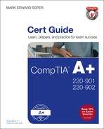
Windows includes the CHKDSK program to check disk drives for errors. It can be run from the Windows GUI (where it is known as Error-Checking) or from the command line.
Windows 8/8.1’s version (see Figure 13-23) is able to test and repair the system drive without rebooting the system.

Figure 13-23 Windows C: Properties Sheet and Error Checking dialogs after the Check now button has been clicked (Windows 8.1).
It’s no coincidence that error-checking (Check now) is listed before Defragmentation (Optimize) in the Windows disk Tools menu. You should check the drive for errors first before you perform a defrag operation.
Windows Vista/7’s version (see Figure 13-24) provides options to automatically fix file system errors and attempt the recovery of bad sectors with CHKDSK. If you select the option to automatically fix file system errors on the system drive, CHKDSK will be scheduled to run at the next restart. This is necessary because CHKDSK requires exclusive access to the drive. CHKDSK performs a three-phase test of the drive after the system is rebooted but before the Windows desktop appears. The results are reported after the Windows desktop appears.

If a non-system drive is tested with Windows Vista/7 with the file system error check enabled, the check happens immediately, and the results are posted immediately. A post-check report like the one shown in Figure 13-25 is displayed if any errors are detected on either a system or non-system disk. To view details as in Figure 13-25, click the Show details down arrow.
You can also run CHKDSK from the command prompt in elevated mode. For options, type CHKDSK /? from the command prompt.
Using Hard Disk Diagnostics
Most hard disk vendors provide diagnostic programs that can be used to test drives for errors. The latest versions of these programs can be obtained from the drive vendors’ websites.
Typically, these programs offer a quick and a long test option. To determine whether a hard disk is functioning, run the quick test first (see Figure 13-26). If the drive passes, use the long test to determine whether the drive is working within specifications.

Figure 13-26 Performing a quick test on a Western Digital hard disk with vendor-supplied diagnostic software.
During the long test, defective areas on the drive can be replaced by spare capacity built in to the drive. Because defective areas on the disk might not be able to be moved to another location, drive vendors often recommend you perform a full backup before testing a hard disk.
Using Data Recovery Software
If you cannot restore a hard disk to health but do not have up-to-date backups of the data it contains, you might need to use data recovery software to attempt to locate and rescue your data.
Caution
To avoid data loss, never install a data recovery program on a drive that you are attempting to recover data from. And make sure you select a program that copies the data located to another drive. Because the need for data recovery is often caused by a failing drive, it’s essential to make sure the data is safe after it is recovered.
There are three levels of data recovery software to consider:
![]() Do-it-yourself data recovery
Do-it-yourself data recovery
![]() Commercial data recovery software
Commercial data recovery software
![]() Data recovery services
Data recovery services
By booting with a Linux Live CD or Live USB distribution (distro) that supports Windows file systems (most systems use NTFS), you can often recover your data by copying it to a different drive. The KNOPPIX Linux Live CD and Live USB (http://www.knoppix.org/) and Parted Magic (https://partedmagic.com/) distros are often used for this purpose.
Many vendors offer data recovery software, and most provide trial versions that you can use to preview your results. These programs work by bypassing normal disk structures, such as partitions and root directories, to access the disk contents directly.
If you cannot retrieve data with a bootable disc, USB drive, or with data recovery software, your last alternative is to use a data recovery service. These services can cost hundreds or thousands of dollars, but if you need to recover large amounts of customer data, accounting data, or line-of-business information, these services might be worth the money. These services can be performed remotely on drives that don’t have physical damage to circuit boards or read-write heads, but some recovery services also use clean rooms that enable the safe dismantling of damaged drives so that defective read-write heads or other components can be replaced.
Troubleshooting Video, Projector, and Display Issues
Desktop, laptop, and mobile users alike need displays that work properly. Use the following sections to learn how to diagnose and fix problems with displays.
VGA Mode
A Windows system starts in VGA mode if Low-resolution mode or Safe Mode has been selected at startup (see Chapter 22 for details) or if the correct drivers are not available. Check the following:
![]() Make sure correct chipset (motherboard/system) drivers have been installed—Many business desktops and most laptops use CPU-integrated graphics. Until chipset drivers are installed, these are used as ordinary VGA GPUs. Download the latest system or motherboard drivers from the vendor.
Make sure correct chipset (motherboard/system) drivers have been installed—Many business desktops and most laptops use CPU-integrated graphics. Until chipset drivers are installed, these are used as ordinary VGA GPUs. Download the latest system or motherboard drivers from the vendor.
![]() If the system is being upgraded from integrated graphics to a separate video card, be sure to install the new drivers after the card is installed—Download the latest graphics from the card vendor or GPU vendor: www.amd.com (Radeon, Fire GL) or www.nvidia.com (GeForce, Quadro).
If the system is being upgraded from integrated graphics to a separate video card, be sure to install the new drivers after the card is installed—Download the latest graphics from the card vendor or GPU vendor: www.amd.com (Radeon, Fire GL) or www.nvidia.com (GeForce, Quadro).
![]() If the system is being upgraded by replacing an existing video card with a new video card with a different manufacturer’s chipset, be sure to uninstall the current video card drivers and support apps from Device Manager and Programs—Install the new drivers after the new card is installed.
If the system is being upgraded by replacing an existing video card with a new video card with a different manufacturer’s chipset, be sure to uninstall the current video card drivers and support apps from Device Manager and Programs—Install the new drivers after the new card is installed.
Until the new card’s drivers are installed, the card will function as a VGA card (no 3D acceleration, limited video modes).
No Image on Screen
The possible causes and solutions for no image on screen vary according to the computer and display type.
Laptop/Tablet/Convertible 2-1
With a laptop or tablet, the most likely cause for no image on the built-in screen is a failure of the LCD-CCFL, LCD-LED, or OLED display, particularly if there is no external display plugged in.
If an external display is plugged in, the computer might be configured to use the external display only. To quickly determine if the built-in display is working, turn off the external display, shut down the computer, and unplug the display from the computer’s video port. Turn the computer back on and see if the built-in display now works. If it does, then configure the built-in display as primary and the external display as a mirror or as an extended desktop. Note that OS X is not designed to use an external display only unless it is being run in keyboard-closed mode.
Desktop Computer
If an external display has no image on screen when it is the only display, check power, display cables, and input setting on the display. If these check out, use a flashlight to determine if there is any image on-screen. If you see one, the LCD-CCFL backlight has failed. If you don’t see any image, the display has failed.
If a secondary or additional display or projector has no image, set the display properties for extended desktop or mirror as desired.
Projector
Check the lens cap or shutter and make sure it is open. Check the image source selection. Make sure the computer source is configured to use the projector as an extended desktop or mirror of the primary display. Check power and video cables.
Overheat Shutdown
Projectors shut down when they overheat. To avoid overheat shutdown, check the following:
![]() Clean or replace filters when recommended. Projectors with filters usually display a message on-screen when it is time to clean or replace the filter.
Clean or replace filters when recommended. Projectors with filters usually display a message on-screen when it is time to clean or replace the filter.
![]() Make sure the projector has adequate ventilation.
Make sure the projector has adequate ventilation.
![]() Check air intakes and exhaust ports for dust and dirt and clean as necessary.
Check air intakes and exhaust ports for dust and dirt and clean as necessary.
![]() Use lower brightness setting on projectors to reduce heat.
Use lower brightness setting on projectors to reduce heat.
![]() Be sure to allow the projector to cool down completely before removing it from power.
Be sure to allow the projector to cool down completely before removing it from power.
A video card (GPU) that overheats will usually display screen artifacts before shutting down.
Dead Pixels
Dead pixels (black pixels) typically result from manufacturing defects in an LCD screen. Check with the manufacturer of the panel or laptop to determine the number of dead pixels that are needed to qualify for screen replacement.
Some “dead” pixels are actually stuck on (bright) or off (dark). There are a variety of ways to solve this problem. They include:
![]() Navigate to the JScreenFix website (www.jscreenfix.com) and start the pixel fixer app. Drag the app window to the area of your screen with the pixel problem and leave it over the area for up to 10 minutes. JScreenFix uses HTML5 and JavaScript controls in the web browser to work. Works with any LCD or OLED device including mobile devices.
Navigate to the JScreenFix website (www.jscreenfix.com) and start the pixel fixer app. Drag the app window to the area of your screen with the pixel problem and leave it over the area for up to 10 minutes. JScreenFix uses HTML5 and JavaScript controls in the web browser to work. Works with any LCD or OLED device including mobile devices.
![]() Gently massage the stuck pixel with a stylus or other objects with a blunt, narrow end. See http://www.wikihow.com/Fix-a-Stuck-Pixel-on-an-LCD-Monitor for illustrations.
Gently massage the stuck pixel with a stylus or other objects with a blunt, narrow end. See http://www.wikihow.com/Fix-a-Stuck-Pixel-on-an-LCD-Monitor for illustrations.
![]() For Windows systems, download and run the UDPixel utility (http://udpix.free.fr/index.php). Requires .NET Framework 2.0, which can be added to Windows 7/8/8.1/10 through Control Panel’s Add/Remove Windows Features.
For Windows systems, download and run the UDPixel utility (http://udpix.free.fr/index.php). Requires .NET Framework 2.0, which can be added to Windows 7/8/8.1/10 through Control Panel’s Add/Remove Windows Features.
Artifacts
Display or screen artifacts (distorted shapes, colors, pixelated images, scrambled text, lines through an image) can be caused by an overheated GPU, projector, overclocked GPU, overcompressed graphics, overcompressed video, and enlarging a low-resolution video or image to a higher-resolution display.
To solve overheating problems with a projector, see “Overheat Shutdowns.” To solve overheating problems with a GPU (video card):
![]() Check the card’s cooling fan
Check the card’s cooling fan
![]() Check the CPU heatsink/fan with CPU-integrated video
Check the CPU heatsink/fan with CPU-integrated video
![]() Disable overclocking and return the card/system to normal clock speeds
Disable overclocking and return the card/system to normal clock speeds
To solve problems with video or graphics compression and sizing:
![]() Capture or shoot videos and photos in high resolution, best quality and reduce to needed size.
Capture or shoot videos and photos in high resolution, best quality and reduce to needed size.
![]() Use H.264 compression for MPEG-4 video to obtain high video quality at a reasonable size.
Use H.264 compression for MPEG-4 video to obtain high video quality at a reasonable size.
![]() Save JPEG at Adobe Photoshop quality settings of 8 or higher (maximum quality is 12) or 75 percent or higher quality (other photo editors) to obtain high photo quality at a reasonable size.
Save JPEG at Adobe Photoshop quality settings of 8 or higher (maximum quality is 12) or 75 percent or higher quality (other photo editors) to obtain high photo quality at a reasonable size.
![]() Always work from an original image for conversions and editing. Editing and converting a compressed version leads to loss of image quality over time.
Always work from an original image for conversions and editing. Editing and converting a compressed version leads to loss of image quality over time.
Incorrect Color Patterns
Incorrect color patterns on a projector can have several causes:
![]() Check the signal type in the projector menu and change it if incorrect.
Check the signal type in the projector menu and change it if incorrect.
![]() If one LCD panel (red, green, or blue) is failing in an LCD projector, replace the panel. Blue panels often fail before others due to ultraviolet light.
If one LCD panel (red, green, or blue) is failing in an LCD projector, replace the panel. Blue panels often fail before others due to ultraviolet light.
![]() On a DLP projector, check the LED light sources (red, green, or blue) or dichroic mirrors.
On a DLP projector, check the LED light sources (red, green, or blue) or dichroic mirrors.
![]() Clean the projector LCD panels if odd-colored specks are visible.
Clean the projector LCD panels if odd-colored specks are visible.
![]() If a laptop has been serviced or upgraded, the LCD ribbon connector to the motherboard might have been damaged. If an external display works correctly, check the LCD ribbon cable inside the laptop.
If a laptop has been serviced or upgraded, the LCD ribbon connector to the motherboard might have been damaged. If an external display works correctly, check the LCD ribbon cable inside the laptop.
![]() Check a VGA cable for bent or broken pins (some pins are not present by default). Check all video cables for cracked outer casings and loose or damaged connectors.
Check a VGA cable for bent or broken pins (some pins are not present by default). Check all video cables for cracked outer casings and loose or damaged connectors.
Dim Image
A dim image can be caused by settings issues or by equipment failure. Check the following:
![]() Check screen brightness control on the displays or projector.
Check screen brightness control on the displays or projector.
![]() If a display management program is being run (Intel, NVIDIA, AMD install these as part of their 3D GPU driver), check its settings.
If a display management program is being run (Intel, NVIDIA, AMD install these as part of their 3D GPU driver), check its settings.
![]() On a laptop, tablet, or mobile device, check the built-in screen brightness setting.
On a laptop, tablet, or mobile device, check the built-in screen brightness setting.
![]() On a projector, check the projector bulb. Some of them become milky, which reduces light output, near the end of their service life.
On a projector, check the projector bulb. Some of them become milky, which reduces light output, near the end of their service life.
![]() On a device that uses a CCFL backlight, check the inverter. A failing inverter can cause a dim display before it fails. The inverter can be replaced separately from the LCD panel or backlight.
On a device that uses a CCFL backlight, check the inverter. A failing inverter can cause a dim display before it fails. The inverter can be replaced separately from the LCD panel or backlight.
Flickering Image
A flickering image can have many causes:
![]() Before looking at hardware replacements, be sure to try updating the GPU (video card) or chipset drivers.
Before looking at hardware replacements, be sure to try updating the GPU (video card) or chipset drivers.
![]() On displays using an LCD-CCFL backlight, flickering could be caused by a failing inverter or a failing backlight—Inverters are relatively inexpensive and can sometimes be replaced without a complete teardown. Backlights cost more and it may make more sense to buy a replacement LCD screen or retire the computer or display.
On displays using an LCD-CCFL backlight, flickering could be caused by a failing inverter or a failing backlight—Inverters are relatively inexpensive and can sometimes be replaced without a complete teardown. Backlights cost more and it may make more sense to buy a replacement LCD screen or retire the computer or display.
![]() On any type of LCD display (CCFL or LED backlight), loose internal cables can cause flickering. Some 2-in-1 convertible devices (tablet/laptop) have hinge problems that can lead to flicker.
On any type of LCD display (CCFL or LED backlight), loose internal cables can cause flickering. Some 2-in-1 convertible devices (tablet/laptop) have hinge problems that can lead to flicker.
![]() On desktop computers, check the power connector to the PCIe card (if it uses a separate power cable) and the power supply itself—If the problem happens after the computer’s been running for a while, it could indicate a heat-related problem.
On desktop computers, check the power connector to the PCIe card (if it uses a separate power cable) and the power supply itself—If the problem happens after the computer’s been running for a while, it could indicate a heat-related problem.
Distorted Image
A distorted image can have several causes and solutions, including the following:
![]() If image tearing or distortion occurs in 3D games only, change video drivers—In most cases, the newest video driver is recommended, but in a few cases with certain games, the best short-term fix might be to install an older driver. Check driver versions with Device Manager’s properties sheet or the proprietary app installed by your GPU or video card maker.
If image tearing or distortion occurs in 3D games only, change video drivers—In most cases, the newest video driver is recommended, but in a few cases with certain games, the best short-term fix might be to install an older driver. Check driver versions with Device Manager’s properties sheet or the proprietary app installed by your GPU or video card maker.
![]() Distortion with DisplayPort connections can be caused by problems with the way some DisplayPort cables and connectors are manufactured—If you can use a different connection (DVI or HDMI) between a system and a display and the problem is no longer present, replace the DisplayPort cable.
Distortion with DisplayPort connections can be caused by problems with the way some DisplayPort cables and connectors are manufactured—If you can use a different connection (DVI or HDMI) between a system and a display and the problem is no longer present, replace the DisplayPort cable.
Distorted Geometry
Distorted geometry (pincushion, barrel, and others) common with CRT displays are not present on LCD or LED displays. However, other factors can cause issues:
![]() If a projector lens is tilted upward or downward toward the screen, keystoning (non-parallel sides on the projected image) is the result (see Figure 13-27). Most projectors have keystone correction options in their display menus or control panels.
If a projector lens is tilted upward or downward toward the screen, keystoning (non-parallel sides on the projected image) is the result (see Figure 13-27). Most projectors have keystone correction options in their display menus or control panels.
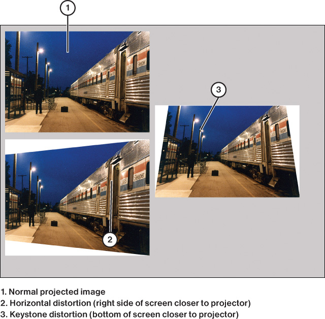
![]() If a projector is not at a 90-degree angle to the projection screen, the image will be larger on one side than the other (see Figure 13-27). Some projectors have adjustments for this problem. If not, adjust the projector or screen position until the image is the same size across the screen.
If a projector is not at a 90-degree angle to the projection screen, the image will be larger on one side than the other (see Figure 13-27). Some projectors have adjustments for this problem. If not, adjust the projector or screen position until the image is the same size across the screen.
![]() When the projector is tilted or is not at a 90-degree angle to the screen, parts of the picture might also be out of focus.
When the projector is tilted or is not at a 90-degree angle to the screen, parts of the picture might also be out of focus.
![]() Curved screen HDTVs have subtle geometric distortions that increase at greater off-axis viewing angles. Place seating closer to the middle of the display.
Curved screen HDTVs have subtle geometric distortions that increase at greater off-axis viewing angles. Place seating closer to the middle of the display.
![]() When viewing 4:3 aspect ratio content on a widescreen display (16:9 or similar), using the zoom option on the HDTV to fill the screen can distort the edges of the image. Try different zoom options or advise the user that the best picture is at the original aspect ratio.
When viewing 4:3 aspect ratio content on a widescreen display (16:9 or similar), using the zoom option on the HDTV to fill the screen can distort the edges of the image. Try different zoom options or advise the user that the best picture is at the original aspect ratio.
Burn-In
Burn-in, the persistent display of a “ghost” image on-screen that was displayed previously, even after the current screen contents have changed, can affect both LCD and plasma displays.
LCD Displays
With LCD displays, stuck pixels are the usual cause. Programs that run constantly changing patterns across the area, such as JScreenFix or UDPixel, can be used to fix the problem.
Another solution is to create an all-white image using a graphics program, set it as the screen saver, and turn down the display brightness. Leave the screen saver running about as long as the original image was on-screen.
To avoid image persistence with IPS displays (the most common type of LCD display in use, offering wide viewing angles), Apple recommends using display sleep to turn off the display when idle. To eliminate a persistent image, enable the screen saver to come on before display sleep and run it as long as the persistent image was originally on-screen. For more information, see https://support.apple.com/en-us/HT202580.
Plasma Displays
Plasma displays use phosphors, which can wear unevenly over time. This was also the cause of burn-in on CRT displays. To avoid either temporary or permanent image persistence, try the following:
![]() For customers who watch mainly 4:3 ratio TV or movie content, advise periodically switching to full-screen (zoomed) mode to avoid black bar persistence on the sides of the image.
For customers who watch mainly 4:3 ratio TV or movie content, advise periodically switching to full-screen (zoomed) mode to avoid black bar persistence on the sides of the image.
![]() Use the screen clean (screen washing) option available on some plasma HDTVs—This puts a constantly changing display across the entire screen.
Use the screen clean (screen washing) option available on some plasma HDTVs—This puts a constantly changing display across the entire screen.
Tip
For plasma and LCD display/HDTV users, there are many YouTube videos that can be played to help fix image retention. To play these on an HDTV, use the HDTV’s Smart TV feature or a set-top box such as a Roku or Amazon Fire TV to go to the YouTube channel. To find these videos, use the search “image retention fix.”
Oversized Images and Icons
Oversized images and icons in Windows can be caused by the following issues:
![]() Booting in Limited resolution (“VGA” mode)—On Windows Vista/7, selecting this mode from the special startup (F8) options menu sets the display for 640×480 resolution. Many apps cannot be used at this resolution, and menus and icons are enormous (see Figure 13-28). To fix, restart the system and select normal resolutions from the Display properties sheet in Control Panel.
Booting in Limited resolution (“VGA” mode)—On Windows Vista/7, selecting this mode from the special startup (F8) options menu sets the display for 640×480 resolution. Many apps cannot be used at this resolution, and menus and icons are enormous (see Figure 13-28). To fix, restart the system and select normal resolutions from the Display properties sheet in Control Panel.

Note
In Windows 8/8.1/10, the Limited resolution option chooses the lowest resolution available on the display’s Resolution slider in Control Panel.
![]() Using the Change the Size of All Items option in Display > Resolution > Make Text Larger or Smaller—100 percent is the default setting. If too large a custom size is selected (such as 200 percent; see Figure 13-29), the effect is the same as if a very low resolution was selected. To fix, select Smaller (see Figure 13-30), log off the user, and log the user back in again.
Using the Change the Size of All Items option in Display > Resolution > Make Text Larger or Smaller—100 percent is the default setting. If too large a custom size is selected (such as 200 percent; see Figure 13-29), the effect is the same as if a very low resolution was selected. To fix, select Smaller (see Figure 13-30), log off the user, and log the user back in again.


Tip
For users who need larger text, use the Change only the text size dialog on this menu.
Network Troubleshooting
Keeping a network running smoothly can be challenging because a single problem could have multiple causes and solutions. Understand the problems and solutions in the following sections are not just for the 220-901 exam but to aid in your ongoing work.
No Connectivity
No connectivity errors can have several causes:
![]() Check the power supply going to the hub, switch, wireless access point, or router. Reset the device.
Check the power supply going to the hub, switch, wireless access point, or router. Reset the device.
![]() If only the users connected to a new switch that is connected to an existing switch lose their network connection, check the connection between the existing switch and the new one. Most switches have an uplink port that is used to connect an additional switch. You can either use the uplink port or the regular port next to the uplink port, but not both. Connect the computer using the port next to the uplink port to another port to make the uplink port available for connecting the new hub or switch.
If only the users connected to a new switch that is connected to an existing switch lose their network connection, check the connection between the existing switch and the new one. Most switches have an uplink port that is used to connect an additional switch. You can either use the uplink port or the regular port next to the uplink port, but not both. Connect the computer using the port next to the uplink port to another port to make the uplink port available for connecting the new hub or switch.
![]() If the uplink port appears to be connected properly, check the cable. Uplink ports perform the crossover for the user, enabling you to use an ordinary network cable to add a hub or switch.
If the uplink port appears to be connected properly, check the cable. Uplink ports perform the crossover for the user, enabling you to use an ordinary network cable to add a hub or switch.
Tip
If you use a crossover cable, you must connect the new hub or switch through a regular port, not the uplink port.
APIPA/Link-Local Address
An APIPA/Link-Local address (IPv4 169.254.x.x range) is assigned to a computer if the DHCP server (which assigns IP addresses) cannot be reached. This is one cause of limited connectivity.
Check the device that provides DHCP service (usually a router on a SOHO network). If that device is working properly, restart the computer and check the IP address after the computer restarts. If the problem persists, check for a bad cable or inability to connect to a wireless network.
Limited Connectivity/Local Connectivity
The yellow ! symbol next to the network icon in the Windows taskbar (see Figure 13-31) indicates the network has limited connectivity (the Internet cannot be reached), also called local connectivity.

Before following the next steps, check connectivity on other devices on the network. If all devices can’t connect:
![]() To diagnose this problem with Windows Vista/7, open the Network and Sharing Center and click the red X in the Internet connection dialog. This launches an Internet troubleshooter. Follow the troubleshooter’s recommendations.
To diagnose this problem with Windows Vista/7, open the Network and Sharing Center and click the red X in the Internet connection dialog. This launches an Internet troubleshooter. Follow the troubleshooter’s recommendations.
![]() With Windows 8/8.1/10, use Search to locate and start the Internet troubleshooter. Follow the troubleshooter’s recommendations.
With Windows 8/8.1/10, use Search to locate and start the Internet troubleshooter. Follow the troubleshooter’s recommendations.
![]() For connection problems with any OS, turn off the broadband modem or access device, wait about a minute, and then turn it on. Then, turn off the router, wait about a minute, and turn it on again. If the problem was with the broadband modem/access device, this should solve the problem. If not, contact the ISP as the problem might be on their network.
For connection problems with any OS, turn off the broadband modem or access device, wait about a minute, and then turn it on. Then, turn off the router, wait about a minute, and turn it on again. If the problem was with the broadband modem/access device, this should solve the problem. If not, contact the ISP as the problem might be on their network.
![]() If only one device is affected, disconnect from a wireless network and reconnect to it. For a wired network, restart the computer.
If only one device is affected, disconnect from a wireless network and reconnect to it. For a wired network, restart the computer.
Local Connectivity
See “Limited Connectivity” earlier for details.
Intermittent Connectivity
Intermittent connectivity can be caused by:
![]() Dead spots (poor signal) on a wireless network—Relocate the wireless router.
Dead spots (poor signal) on a wireless network—Relocate the wireless router.
![]() Too many networks using same channel—Use a wireless network scanning device or app to see local wireless networks and their channels. Reconfigure network to use a channel with less traffic.
Too many networks using same channel—Use a wireless network scanning device or app to see local wireless networks and their channels. Reconfigure network to use a channel with less traffic.
![]() EMI or RFI interference with wired network—Alarm systems, elevators, fluorescent lights, and motors can interfere with networks running UTP. Switch to STP cable or relocate cables away from interference.
EMI or RFI interference with wired network—Alarm systems, elevators, fluorescent lights, and motors can interfere with networks running UTP. Switch to STP cable or relocate cables away from interference.
![]() Defective network cable, such as cracked outer jacket or broken locking tab—Replace cable.
Defective network cable, such as cracked outer jacket or broken locking tab—Replace cable.
![]() Problems with ISP’s Internet service—Contact ISP after troubleshooting local network if problem persists.
Problems with ISP’s Internet service—Contact ISP after troubleshooting local network if problem persists.
IP Conflict
An IP conflict results if two devices on a network have the same IP address. A common cause is if a DHCP server assigns the same address that has been assigned manually to a device on the network. Configure devices with manual IP addresses to use a different range of addresses than those used by the DHCP server.
Slow Transfer Speeds
Significant drops in network performance and slow transfer speeds can be traced to a variety of causes, including
![]() Damage to cables, connectors, hubs, switches, and routers—Check cables for damage.
Damage to cables, connectors, hubs, switches, and routers—Check cables for damage.
![]() Connecting high-speed NICs to low-speed switches—When using Gigabit Ethernet switches and routers, confirm that all devices on the network (switches, router, cables, and NICs) meet Gigabit Ethernet standards (CAT 5e or 6, 6a, 7 cable) and are configured to use Gigabit Ethernet.
Connecting high-speed NICs to low-speed switches—When using Gigabit Ethernet switches and routers, confirm that all devices on the network (switches, router, cables, and NICs) meet Gigabit Ethernet standards (CAT 5e or 6, 6a, 7 cable) and are configured to use Gigabit Ethernet.
![]() Fast local connections but sluggish Internet connections can be caused by too much demand for the Internet connection (may be due to multiple downloads or streaming services) or Internet congestion outside the home or office.
Fast local connections but sluggish Internet connections can be caused by too much demand for the Internet connection (may be due to multiple downloads or streaming services) or Internet congestion outside the home or office.
![]() RFI/EMI interference with wireless networks—Check wireless phones and microwave ovens to see if their use interferes with the network. Move router away from interference sources. Switch to a wireless 802.11ac router and NICs and use 5GHz band to avoid most of this type of interference.
RFI/EMI interference with wireless networks—Check wireless phones and microwave ovens to see if their use interferes with the network. Move router away from interference sources. Switch to a wireless 802.11ac router and NICs and use 5GHz band to avoid most of this type of interference.
Low RF Signal
A low RF signal on a wireless network can be caused by:
![]() Interference from other wireless networks—Use a wireless network analyzer to determine the least-used channels for your network and switch to one of those channels.
Interference from other wireless networks—Use a wireless network analyzer to determine the least-used channels for your network and switch to one of those channels.
![]() Concrete or masonry walls in the building—If it is not possible to relocate the router, add repeaters. In residential construction, consider using powerline repeaters.
Concrete or masonry walls in the building—If it is not possible to relocate the router, add repeaters. In residential construction, consider using powerline repeaters.
![]() Improper antenna positioning on the router or NICs with adjustable antennas—Follow manufacturer’s recommendations.
Improper antenna positioning on the router or NICs with adjustable antennas—Follow manufacturer’s recommendations.
![]() The router or NICs do not support MIMO—MIMO (multiple in, multiple out) antennas are characteristic of higher-speed Wireless-N (300Mbp or faster-rated hardware) and all Wireless-AC equipment. Upgrade the router to the best Wireless-AC model in the clients’ price range, even if clients are using Wireless-N, as it will improve performance at a given distance. Upgrading clients to Wireless-AC as well will improve performance even more.
The router or NICs do not support MIMO—MIMO (multiple in, multiple out) antennas are characteristic of higher-speed Wireless-N (300Mbp or faster-rated hardware) and all Wireless-AC equipment. Upgrade the router to the best Wireless-AC model in the clients’ price range, even if clients are using Wireless-N, as it will improve performance at a given distance. Upgrading clients to Wireless-AC as well will improve performance even more.
Note
Some Wireless-AC routers now support multi-user MIMO (MU-MIMO). MU-MIMO enables a router to make MIMO connections to multiple users at the same time. MU-MIMO requires routers and client device support, but it can be implemented on client devices that have only a single antenna. As firmware and drivers updates become available to enable MU-MIMO on routers and client devices, MU-MIMO will become more common. To learn more, see www.techhive.com/article/2928725/how-mu-mimo-wi-fi-works.html.
SSID Not Found
If the SSID is configured not to broadcast its name, users can still connect to it. It is listed as a Hidden network in the list of wireless networks in Windows. Users must supply the SSID as well as an encryption key to make the connection.
If an SSID not found error is displayed (either by name or as Hidden network), reboot the router. If rebooting the router does not help, open its configuration web page from your router (most SOHO routers use the IP address 192.168.1.1) and verify that it is configured as a router. Change and save configuration, and try the connection again.
Quick Reference to Network Hardware Tools
The following network hardware tools are useful for troubleshooting wired or wireless networks:
![]() Cable tester—Checks cables for proper connectivity.
Cable tester—Checks cables for proper connectivity.
![]() Loopback plug—Returns sent signals for comparison by a network card/cable testing program.
Loopback plug—Returns sent signals for comparison by a network card/cable testing program.
![]() Punchdown tools—Use to create or repair wired connections to a patch panel.
Punchdown tools—Use to create or repair wired connections to a patch panel.
![]() Tone generator and probe—Use to test network cable for problems.
Tone generator and probe—Use to test network cable for problems.
![]() Wire strippers—Use to prepare network cable for assembly.
Wire strippers—Use to prepare network cable for assembly.
![]() Crimper—Use to attach coaxial or TP connectors to a cable.
Crimper—Use to attach coaxial or TP connectors to a cable.
![]() Wireless locator—Displays available wireless networks and their channels. Use to locate a wireless network or to find an unused channel.
Wireless locator—Displays available wireless networks and their channels. Use to locate a wireless network or to find an unused channel.
To learn more about using these hardware tools for troubleshooting a network, see the “Using Networking Tools” section in Chapter 11.
Overview of Network Command-Line Tools
Windows contains several command-line tools for troubleshooting and configuring the network. These include the following:
![]() NET—Displays and uses network resources
NET—Displays and uses network resources
![]() PING—Tests TCP/IP and Internet connections
PING—Tests TCP/IP and Internet connections
![]() TRACERT—Traces the route between a specified website or IP address and your PC. The equivalent command in OS X and Linux is Traceroute.
TRACERT—Traces the route between a specified website or IP address and your PC. The equivalent command in OS X and Linux is Traceroute.
![]() NSLOOKUP—Displays detailed information about DNS
NSLOOKUP—Displays detailed information about DNS
![]() IPCONFIG—Displays detailed TCP/IP configuration about your Windows system
IPCONFIG—Displays detailed TCP/IP configuration about your Windows system
![]() NETSTAT—Displays protocol statistics and current TCP/IP network connections
NETSTAT—Displays protocol statistics and current TCP/IP network connections
![]() NBTSTAT—Displays protocol statistics and current TCP/IP connections using NBT (NetBIOS over TCP/IP)
NBTSTAT—Displays protocol statistics and current TCP/IP connections using NBT (NetBIOS over TCP/IP)
![]() NETDOM—Administers Active Directory domains and trust relationships. Installed as part of Windows Server, but can be downloaded for use with Windows desktop OS versions.
NETDOM—Administers Active Directory domains and trust relationships. Installed as part of Windows Server, but can be downloaded for use with Windows desktop OS versions.
Commands can be entered in uppercase, lowercase, or mixed case.
The following sections describe these tools, including ifconfig.
PING
Windows can use the PING command to test TCP/IP, check for connectivity to other hosts on the network, and check the Internet connection for proper operation. PING is a more reliable way to check an Internet connection than opening your browser because a misconfigured browser could cause you to think that your TCP/IP configuration is incorrect.
To use PING to check connectivity with another host on the network, follow this procedure:
Step 1. Open a command-prompt window.
Step 2. Type PING IPaddress or PING servername to ping another host on the network; then press Enter. For example, to ping a router on a SOHO network, typical syntax would be PING 192.168.1.1.
To use PING to check your Internet connection, follow this procedure:
Step 1. Start your Internet connection. If you use a LAN to connect to the Internet, you might have an always-on connection.
Step 2. Open a command-prompt window.
Step 3. Type PING IPaddress or PING servername and press Enter. For example, to ping a web server called www.erewhon.net, type PING www.erewhon.net.
By default, PING sends four data packets from your computer to any IP address or servername you specify. If your TCP/IP connection is working properly, you should see a reply from each ping you sent out indicating how quickly the signals traveled back from the target and the IP address or URL of the target. Note that some websites and servers are configured to ignore pings as a security measure. The replies indicate that the host is alive. Any other message would indicate a problem; for example, the “Request timed out” or “Destination host unreachable” messages would require further troubleshooting. Keep in mind that if the local computer is configured incorrectly, you might not be able to “ping” anything! Also watch for the amount of time the ping took to reply back. A longer latency time could indicate network congestion. Conversely, the lower the time in milliseconds (ms), the faster your connection. Connection speeds vary a great deal due to various factors, such as Internet network congestion, server speed, and the number of relays needed to transfer your request from your computer to the specified server. To check relay information, use the TRACERT command.
IPCONFIG
The IPCONFIG command-line utility is used to display the computer’s current IP address, subnet mask, and default gateway (see Figure 13-32). Ipconfig combined with the /all switch will show more information including the DNS server address and MAC address, which is the hexadecimal address that is burned into the ROM of the network adapter.

If you’re having problems seeing other computers on the network or connecting to the Internet on a network that uses server-assigned IPv4 addresses, type ipconfig /release and press Enter; then type ipconfig /renew and press Enter to obtain a new IP address from the DHCP server on your network. The comparable commands for releasing/renewing an IPv6 address are ipconfig /release6 and ipconfig /renew6.
IFCONFIG
The IFCONFIG command is used by Linux and OS X (see Figure 13-33) to display detailed information about the computer’s current IP configuration. Linux and OS X refer to an IPv4 address as “inet,” and an IPv6 address as “inet6.”

TRACERT
The TRACERT command is used by Windows to trace the route taken by data traveling from your computer to an IP address or website you specify. By default, TRACERT checks up to 30 hops between your computer and the specified website or IP address. To use TRACERT to check the routing, follow this procedure:
Step 1. Start your Internet connection. If you use a LAN to connect to the Internet, you might have an always-on connection.
Step 2. Open a command-prompt window.
Step 3. Type TRACERT IP address or TRACERT servername and press Enter. For example, to trace the route to a web server called www.erewhon.tv, typing TRACERT www.erewhon.tv. TRACERT displays the IP addresses and URLs of each server used to relay the information to the specified location, as well as the time required.
To see help for the TRACERT command, type TRACERT without any options and press the Enter key.
NETSTAT
Most commonly NETSTAT is used to show the current connections to a remote computer. Let’s say you connected to google.com, opened a command prompt, and typed NETSTAT. You would get several results, one of which would look similar to this:
TCP 192.168.0.5:49732 google.com:80 Established
The NETSTAT command shows only TCP connections. If you were interested in seeing both TCP and UDP connections, you could use the command NETSTAT –a. And to see the information in numerical format, use NETSTAT –n. This displays IP addresses instead of domain names as shown here:
TCP 92.168.0.5:49732 74.125.113.106:80 Established
NETSTAT can also be used to show the network adapter’s Ethernet statistics with the NETSTAT –e command. Check out the other various switches by typing NETSTAT /?.
NBTSTAT
NBTSTAT can be used to show the services running on the local computer or a remote computer. It calls this the name table. For example, you could find out what services are running, what the computer’s name is, and what network it is a part of by typing NBTSTAT –a 192.168.0.5 (or whatever your local IP is). The results would be similar to the following:
Computer1 <00> Unique Registered
Workgroup <00> Group Registered
Computer1 <20> Unique Registered
The computer and network names are easy to see: Computer1 and Workgroup. But also notice that there are numbers in alligators such as <00> and <20>. These are the services mentioned previously. <00> is the workstation service, the service that allows your computer to redirect out to other systems to view shared resources. <20> is the server service that allows your computer to share resources with other systems. Check out the other various switches by typing NBTSTAT /?.
NET
Windows includes the NET command for use in displaying and using network resources from the command prompt. Some of the NET commands you can use include
![]() Net Help—Displays help for a Net option; for example, use Net Help View for help with the Net View command.
Net Help—Displays help for a Net option; for example, use Net Help View for help with the Net View command.
![]() Net Use—Maps a network drive to a shared resource on the network; for example, Net Use Q: \Tiger1shared. In this example, Q: will behave just like any other drive letter such as C:, D:, and so on. The only difference is that it will redirect to another computer on the network.
Net Use—Maps a network drive to a shared resource on the network; for example, Net Use Q: \Tiger1shared. In this example, Q: will behave just like any other drive letter such as C:, D:, and so on. The only difference is that it will redirect to another computer on the network.
![]() Net View—Displays other hosts on the network.
Net View—Displays other hosts on the network.
![]() Net Helpmsg errorcode#—Displays the meaning of any Microsoft error code.
Net Helpmsg errorcode#—Displays the meaning of any Microsoft error code.
To display a complete list of Net commands, type Net /? |More from the command prompt.
NETDOM
The NETDOM command is used to manage Active Directory. To install it on a Windows desktop computer, download and install Remote Server Administration Tools (RSAT) from the Microsoft website. To run Netdom, open an elevated command prompt.
Netcom commands include:
![]() Netdom add—Adds a workstation or server account to the domain.
Netdom add—Adds a workstation or server account to the domain.
![]() Netdom computername—Manages the primary and alternate names for a computer. This command can safely rename Active Directory domain controllers as well as member servers.
Netdom computername—Manages the primary and alternate names for a computer. This command can safely rename Active Directory domain controllers as well as member servers.
![]() Netdom join—Joins a workstation or member server to a domain. The act of joining a computer to a domain creates an account for the computer on the domain, if it does not already exist.
Netdom join—Joins a workstation or member server to a domain. The act of joining a computer to a domain creates an account for the computer on the domain, if it does not already exist.
![]() Netdom move—Moves a workstation or member server to a new domain. The act of moving a computer to a new domain creates an account for the computer on the domain, if it does not already exist.
Netdom move—Moves a workstation or member server to a new domain. The act of moving a computer to a new domain creates an account for the computer on the domain, if it does not already exist.
![]() Netdom query—Queries the domain for information such as membership and trust.
Netdom query—Queries the domain for information such as membership and trust.
![]() Netdom remove—Removes a workstation or server from the domain.
Netdom remove—Removes a workstation or server from the domain.
![]() Netdom renamecomputer—Renames a domain computer and its corresponding domain account. Use this command to rename domain workstations and member servers only. To rename domain controllers, use the netdom computername command.
Netdom renamecomputer—Renames a domain computer and its corresponding domain account. Use this command to rename domain workstations and member servers only. To rename domain controllers, use the netdom computername command.
![]() Netdom reset—Resets the secure connection between a workstation and a domain controller.
Netdom reset—Resets the secure connection between a workstation and a domain controller.
![]() Netdom resetpwd—Resets the computer account password for a domain controller.
Netdom resetpwd—Resets the computer account password for a domain controller.
![]() Netdom trust—Establishes, verifies, or resets a trust relationship between domains.
Netdom trust—Establishes, verifies, or resets a trust relationship between domains.
![]() Netdom verify—Verifies the secure connection between a workstation and a domain controller.
Netdom verify—Verifies the secure connection between a workstation and a domain controller.
For more information about Netdom, see https://technet.microsoft.com/en-us/library/cc772217.aspx.
NSLOOKUP
NSLOOKUP is a command-line tool used to determine information about the DNS. When NSLookup is run without options, it displays the name and IP address of the default DNS server before displaying a DNS prompt. Enter the name of a website or server to determine its IP address; enter the IP address of a website or server to determine its name. Enter a question mark (?) at the prompt to see more options; type exit, and then press Enter to exit the program.
Mobile Device Troubleshooting
With more organizations than ever using laptops, tablets, and smartphones, it’s important to know how to troubleshoot devices on the go. You need to understand the following concepts for the 220-901 exam and to improve your technical skills.
No Display
On a laptop, no display can be caused by the failure of the LCD inverter or backlight, a damaged cable leading to or from an LCD inverter, the failure of the LED control board, the failure of the display panel, the failure of the onboard display circuit, or by toggling the laptop to use an external display only with an Fn-key.
First, try toggling the laptop to use the internal display. If this doesn’t help, connect it to a monitor or projector. If the external display works, the problem might be with the cable to the LCD inverter or the LCD inverter or the LCD-CCFL backlight on an LED display, or the problem could be with the cable to the LED control board, the LED control board, or the LED backlight. If the external display doesn’t work, the motherboard needs to be repaired or replaced.
On a tablet or smartphone, the usual cause is that the unit is out of power. Connect it to a suitable charging connection, wait about ten minutes and try to power it up. If there’s still no display, have the unit serviced.
Dim Display
On any device, the first step in dealing with a dim display is to check the brightness settings first. Smartphones and tablets typically use auto brightness. Disable it and try adjusting the brightness manually. Also, check the charge level. Many devices set the screen to a very dim setting right before shutting down in a last-ditch attempt to stretch battery life. If the screen doesn’t return to normal brightness after being connected to AC power, service it.
If a laptop has a dim display not caused by user settings, the most likely cause is the failure of the fluorescent backlight inverter. If the screen flashes for a moment and then becomes dim at startup, the inverter is almost always the cause. Replace it.
If a smartphone or tablet has a dim display that won’t respond to user settings, try performing a hard reset (power down, wait a few moments, than power up again. Also, make sure the ambient light sensor is working and is not being blocked by the case.
If the display dims after the device has been turned on for several minutes and left unattended, the most typical cause is a power management setting. Adjust power management settings as desired.
Flickering Display
On a laptop with an LCD-CCFL backlight, a flickering display is almost always caused by a dying backlight. You can replace it, but it’s easier to swap the complete screen assembly for a remanufactured unit. If the unit has been opened, the problem could also be a damaged LCD ribbon cable to the motherboard.
On an Android smartphone running Jelly Bean or newer editions, you can use the Turn off hardware overlays setting or the Disable hardware overlays setting available in the Developer options menu. To enable developer options:
Step 1. Choose Settings > More > About Device.
Step 2. Tap Build number until the device says “You are now a developer.”
Step 3. Choose Home > Settings > More > Developer options.
Step 4. Choose the hardware overlays setting used by your device.
See http://www.problogbooster.com/2014/06/on-screen-display-flickering-error-android-xda.html for more information.
On an iOS 9 iPhone 6s Plus or 6 Plus, the flickering is usually caused by dropped frames during graphically intense calculations. To fix it:
Step 1. Choose Settings > General > Accessibility > Increase Contrast > Reduce Transparency.
Step 2. Turn on Reduced Transparency.
Some apps will have less appealing backgrounds when this option is enabled. Learn more at http://www.idigitaltimes.com/iphone-6s-plus-screen-flickering-problems-how-fix-frame-drop-issue-486761.
Sticking Keys
Sticking keys on a laptop or tablet usually indicate a problem with the keyboard. It is not always necessary to replace the entire keyboard. Several online vendors offer individual key replacements for laptops. If more than one or two keys are sticking, it may be most cost-effective to replace the entire keyboard.
If the tablet uses a removable keyboard, the keyboard can be replaced if keys are not available.
Note
Some laptop models might use two or more key styles. Use the illustrations available on some sites to determine exactly which key style you need.
Intermittent Wireless
Some tablets and smartphones may have intermittent wireless if the Wi-Fi signal is very weak. Switch to a cellular data connection (if available) until a stronger Wi-Fi signal is available.
Change the angle of your laptop or 2-in-1 device screen or turn the entire unit to help improve Wi-Fi reception, as these units have their antennas in the screen.
Use the signal strength indicator to find the strongest wireless signal that can be used. In a public setting, there might be two or more open networks to choose from.
Battery Not Charging
Battery not charging issues on a tablet or smartphone may be caused by:
![]() Make sure the charger is rated for the tablet or smartphone. Chargers are rated in amperage (1A = 1000mA). A minimum of 500mA is needed to charge a smartphone (1A is much faster), and a minimum of 2.1A is needed to charge a tablet.
Make sure the charger is rated for the tablet or smartphone. Chargers are rated in amperage (1A = 1000mA). A minimum of 500mA is needed to charge a smartphone (1A is much faster), and a minimum of 2.1A is needed to charge a tablet.
![]() If the charger has a toggle for iOS and non-iOS devices, choose the correct setting for your device.
If the charger has a toggle for iOS and non-iOS devices, choose the correct setting for your device.
![]() If you use a USB port on a laptop or desktop computer, enable USB fast charging if it is available on the computer, and be sure to use that port.
If you use a USB port on a laptop or desktop computer, enable USB fast charging if it is available on the computer, and be sure to use that port.
![]() You can’t charge a smartphone from an unpowered USB hub; it has only 100mA available per port.
You can’t charge a smartphone from an unpowered USB hub; it has only 100mA available per port.
![]() Ordinary USB ports cannot charge a device when the computer is asleep.
Ordinary USB ports cannot charge a device when the computer is asleep.
If you have checked these issues with no success, replace the cable. If a known-working cable doesn’t help, replace the battery or have the unit serviced.
On a laptop, if the system works when plugged in to AC power, but not on battery power, check the following:
![]() Make sure the battery is installed properly.
Make sure the battery is installed properly.
![]() Wipe off any corrosion or dirt on the battery and laptop battery contacts.
Wipe off any corrosion or dirt on the battery and laptop battery contacts.
![]() Determine whether the battery can hold a charge. Make sure the battery is properly installed and the AC adapter has proper DC voltage output levels. Leave the system plugged in for the recommended amount of time needed to charge the battery; then try to run the system on battery power. If the battery cannot run the system, or the system runs out of battery power in less than 1 hour, replace the battery. If replacing the battery does not solve the problem, the laptop needs to be serviced or replaced.
Determine whether the battery can hold a charge. Make sure the battery is properly installed and the AC adapter has proper DC voltage output levels. Leave the system plugged in for the recommended amount of time needed to charge the battery; then try to run the system on battery power. If the battery cannot run the system, or the system runs out of battery power in less than 1 hour, replace the battery. If replacing the battery does not solve the problem, the laptop needs to be serviced or replaced.
![]() If the battery is hot after being charged or has a warped exterior, replace it.
If the battery is hot after being charged or has a warped exterior, replace it.
Ghost Cursor/Pointer Drift
A ghost cursor is usually caused by mouse movement too fast for screen refresh rate. To make the mouse pointer easier to see, adjust the mouse properties to slow down mouse acceleration, use a larger mouse pointer, or enable visibility options (pointer trails, or press the Ctrl key to display mouse location).
Pointer drift can be caused by accidentally swiping or pressing on the device’s touchpad or by a problem with the device’s integrated pointing stick. If you use a mouse, disable the touchpad or change its sensitivity settings to ignore accidental touches.
No Power
If the laptop has no power when plugged in to an AC outlet, verify that the battery is not the problem. Remove it.
![]() Make sure the laptop is plugged in to a working AC outlet. Check the outlet with an outlet tester. Use a voltmeter or a multimeter set to AC voltage to determine whether the output is within acceptable limits.
Make sure the laptop is plugged in to a working AC outlet. Check the outlet with an outlet tester. Use a voltmeter or a multimeter set to AC voltage to determine whether the output is within acceptable limits.
![]() Make sure the AC power cord running from the AC outlet to the external AC adapter “power brick” is plugged in completely to the outlet and the adapter. If the power cord or plug is damaged, replace the cord.
Make sure the AC power cord running from the AC outlet to the external AC adapter “power brick” is plugged in completely to the outlet and the adapter. If the power cord or plug is damaged, replace the cord.
![]() To determine whether the adapter is outputting the correct DC voltage, use a voltmeter or multimeter set to DC voltage to test the voltage coming from the adapter and compare it to the nominal output values marked on the adapter. As Figure 13-34 illustrates, it might be necessary to use a bent paperclip to enable an accurate voltage reading. A value of +/– 5 percent is acceptable.
To determine whether the adapter is outputting the correct DC voltage, use a voltmeter or multimeter set to DC voltage to test the voltage coming from the adapter and compare it to the nominal output values marked on the adapter. As Figure 13-34 illustrates, it might be necessary to use a bent paperclip to enable an accurate voltage reading. A value of +/– 5 percent is acceptable.

Num Lock Indicator Lights
Some laptops with embedded keypads don’t start up with the keypad enabled (Num Lock on). Check the BIOS to see if this option can be enabled.
If Num Lock indicator lights will not come on, there might be a problem with the keyboard.
No Wireless Connectivity
Most laptops have a push button, pressure-sensitive touch button, or Fn-key combination to enable or disable Wi-Fi networking. If there is no wireless connectivity, press the button or Fn-key combination to enable the connection. Most laptops display an indicator light when the connection is enabled.
Late-model laptops, tablets, and smartphones have an airplane mode that disables all onboard radios (Wi-Fi, Bluetooth, and cellular) when enabled. Turn off airport mode and try the connection again. Wi-Fi can also be disabled separately from airplane mode. Check the Settings menu and enable Wi-Fi if necessary.
If the connection fails, check the Wi-Fi connection dialog in the notification area. You might need to reconnect manually. If there is no Wi-Fi connection dialog, open the Device Manager and check the Network Adapters category. If the Wi-Fi adapter is not listed, rescan for hardware changes.
If the Wi-Fi adapter cannot be located by Device Manager, shut down the system, disconnect it from all power sources, and open the access panel to the Wi-Fi card. If the card is loose, reconnect it and retry the connection after restoring power and restarting the computer. If the Wi-Fi antenna wires are loose, tighten them.
No Bluetooth Connectivity
Most laptops with built-in Bluetooth have a push button, pressure-sensitive touch button, or a Fn-key combination to enable or disable Bluetooth networking. Here’s how to diagnose problems with no Bluetooth connectivity:
Step 1. If there is no connection, press the button or Fn-key combination to enable the connection. Most laptops display an indicator light when the connection is enabled.
Step 2. If the connection fails, verify that a Bluetooth adapter is installed and enabled. If the Bluetooth adapter is accessible from the outside of the unit, you can physically verify proper connection. Also Check Windows Device Manager, Linux Hardware, or OS X System Information. If the Bluetooth adapter is not listed, restart the computer and verify that the Bluetooth adapter is enabled in system BIOS setup.
Step 3. If the Bluetooth adapter is installed, use the Bluetooth configuration utility provided by the computer vendor (or device vendor, in the case of a USB Bluetooth adapter) to set up the adapter to connect to other devices.
Step 4. If the adapter is already set up to connect to other devices, check the Bluetooth settings on those devices.
On a tablet or smartphone, also check airplane mode (see the “No Wireless Connectivity” section for details).
Cannot Display to External Monitor
To display to an external monitor or projector, use the appropriate keyboard Fn-key combination after connecting the display or projector (see documentation for your device for details). If the system cannot display to external monitor:
![]() Check cabling between the computer and external display.
Check cabling between the computer and external display.
![]() Make sure the display is set to the correct input.
Make sure the display is set to the correct input.
![]() Try a different display to determine if the problem is the mobile device or the external monitor.
Try a different display to determine if the problem is the mobile device or the external monitor.
Touchscreen Non-Responsive
The most common reason for a touchscreen non-responsive problem is dust, dirt, and grease on the surface. Use an antistatic wipe or spray designed for touchscreens to clean it.
Dry hands may not work well with touchscreens. Gloves without special fingertips can’t use a touchscreen.
To determine if the touchscreen has failed, try a stylus made for the touchscreen. Reset the device and retry. If the touchscreen is still not responsive, have the unit serviced.
Apps Not Loading
To solve problems with apps not loading, check the following:
![]() Check available storage space—If your system is almost out of space, apps can’t run. Uninstall apps you never use.
Check available storage space—If your system is almost out of space, apps can’t run. Uninstall apps you never use.
![]() If you have adequate free storage space, the device might not have enough free RAM—Close some apps.
If you have adequate free storage space, the device might not have enough free RAM—Close some apps.
![]() For a web-enabled app, make sure the device has a good Internet connection.
For a web-enabled app, make sure the device has a good Internet connection.
![]() Device overheating—Remove the case, close apps to help cool the unit.
Device overheating—Remove the case, close apps to help cool the unit.
![]() Check power management settings—If a laptop is plugged into AC power, I recommend using the High Performance power setting in Windows.
Check power management settings—If a laptop is plugged into AC power, I recommend using the High Performance power setting in Windows.
![]() Close apps that are running but not in use.
Close apps that are running but not in use.
![]() Don’t charge the phone while running a bunch of apps.
Don’t charge the phone while running a bunch of apps.
Unable to Decrypt Email
Mobile devices that receive messages from Outlook 2010 might be unable to decrypt email. Outlook 2010 changed how it used the Cryptographic Message Service (CMS). Make sure Outlook 2010 is updated to SP1 to solve this problem (which does not exist in Outlook 2013).
Missing or out-of-date security certificates on devices can also cause problems with decrypting email. Update security certificates to solve this problem.
Extremely Short Battery Life
Although Li-Ion batteries do not have the memory effect that plagued old Ni-Cd batteries, various factors can still cause extremely short battery life. Check the following:
![]() Don’t overcharge a device’s battery
Don’t overcharge a device’s battery
![]() For best results, don’t wait until a device is almost out of power to charge it.
For best results, don’t wait until a device is almost out of power to charge it.
![]() Adjust screen brightness to the lowest level that is comfortable to use.
Adjust screen brightness to the lowest level that is comfortable to use.
![]() On iOS devices, turn off background app refresh.
On iOS devices, turn off background app refresh.
![]() Upgrade to the latest OS or OS updates available for your device.
Upgrade to the latest OS or OS updates available for your device.
![]() Use a phone battery helper app to manage charging, but don’t run other apps while the device is charging.
Use a phone battery helper app to manage charging, but don’t run other apps while the device is charging.
![]() Close apps from the iOS App Switcher.
Close apps from the iOS App Switcher.
![]() Shut down an iOS device weekly with the slider switch.
Shut down an iOS device weekly with the slider switch.
![]() On devices that use AMOLED displays, switch to black wallpaper (theme) to save power.
On devices that use AMOLED displays, switch to black wallpaper (theme) to save power.
Overheating
Mobile device overheating can have several causes:
![]() On a laptop, make sure the intake and exhaust fan ports aren’t being blocked during use. Despite the name, a lap is not a suitable place for a computer because clothing can block airflow.
On a laptop, make sure the intake and exhaust fan ports aren’t being blocked during use. Despite the name, a lap is not a suitable place for a computer because clothing can block airflow.
![]() Adjust power settings, especially when on battery power.
Adjust power settings, especially when on battery power.
![]() Make sure CPU power management drivers are installed (check Device Manager under System devices).
Make sure CPU power management drivers are installed (check Device Manager under System devices).
![]() On a tablet or smartphone, shut down unnecessary apps, and keep in mind that HD video playback can stress the processor. Some protective cases can cause smartphones to overheat.
On a tablet or smartphone, shut down unnecessary apps, and keep in mind that HD video playback can stress the processor. Some protective cases can cause smartphones to overheat.
Frozen System
A frozen system is usually caused by a malfunctioning app. Sometimes, going to the lock screen for a few seconds helps a mobile app to start responding. If that doesn’t work, shut down the system, wait a minute, and then restart it. Check for updates for the app and device.
No Sound from Speakers
No sound from speakers can have several causes:
![]() With wired speakers, keep in mind that the case might prevent 3.5mm mini-jack connector from making a good connection. It may be necessary to remove the case to make a good connection.
With wired speakers, keep in mind that the case might prevent 3.5mm mini-jack connector from making a good connection. It may be necessary to remove the case to make a good connection.
![]() With Bluetooth speakers, make sure Bluetooth is turned on. Check device pairing.
With Bluetooth speakers, make sure Bluetooth is turned on. Check device pairing.
![]() Check the volume or mute controls on the mobile device. Apple iPhones have a sliding switch to mute them as well as software controls. The side button on iPads can be configured to lock screen or mute speaker output. Check the volume control on the keyboard or OS on OS X and Windows devices.
Check the volume or mute controls on the mobile device. Apple iPhones have a sliding switch to mute them as well as software controls. The side button on iPads can be configured to lock screen or mute speaker output. Check the volume control on the keyboard or OS on OS X and Windows devices.
GPS Not Functioning
Check the following if the GPS not functioning:
If Airplane mode is on, the GPS is shut down as well. Turn off Airplane mode and the GPS may come back on. If not, turn on the GPS in the Settings > Location menu.
Swollen Battery
A swollen battery is most likely due to overcharging. In addition to replacing the battery, check the AC adapter to make sure it is putting out the correct voltage.
Mobile Device Disassembly Process
Mobile devices, even for experienced technicians, can be a challenge to disassemble. Follow these guidelines to ensure a successful disassembly and reassembly when you upgrade or service a laptop, convertible 2-in-1, tablet, or smartphone.
Document and Label Cable and Screw Locations
A typical laptop may have as many as 100 or more screws of varying sizes. A smartphone could have a dozen or more. Be sure to document and label cable and screw locations: as each screw is removed, note its location and size.
A digital camera or smartphone camera is a good tool, as you can use it to photograph the device and the screws as they are removed.
Figure 13-35 shows a few of the different screws removed from a typical laptop.

If you have a service manual for the device, note the screw sizes and positions listed for each component. Use it to create a checklist as you disassemble a device.
Organize Parts
There are many ways to organize parts:
![]() Use a plastic divided-compartment lidded tray from a hardware store to keep screws and bolts organized. As you put each set of screws into a compartment, add a label to indicate which subassembly they go to.
Use a plastic divided-compartment lidded tray from a hardware store to keep screws and bolts organized. As you put each set of screws into a compartment, add a label to indicate which subassembly they go to.
![]() Place static-sensitive materials (CPU, RAM, etc.) in anti-static bags.
Place static-sensitive materials (CPU, RAM, etc.) in anti-static bags.
![]() Use anti-static bubble wrap for larger components such as motherboards.
Use anti-static bubble wrap for larger components such as motherboards.
![]() Use boxes to protect case and trim components.
Use boxes to protect case and trim components.
Tip
If you have a service manual for the device, label components by the subassembly and page number in the manual.
Refer to Manufacturer Resources
Before you start to disassemble a device, make sure you have the information you need to refer to manufacturer resources.
![]() Get the manufacturer’s service manual if it is available.
Get the manufacturer’s service manual if it is available.
![]() For the easiest time in searching, check the underside of a laptop or tablet to discover the actual service number or catalog number (not the marketing model number).
For the easiest time in searching, check the underside of a laptop or tablet to discover the actual service number or catalog number (not the marketing model number).
Most manufacturers make this information readily available. Some third-party websites also have service manuals, but don’t use these resources unless you can’t download the service manual directly from the website.
Caution
YouTube has many videos on tablet, smartphone, and laptop disassembly. Also, there are many unofficial teardown documents online. They can be helpful in the absence of manufacturer-supplied documentation, but be careful! Some might advocate potentially dangerous methods for disassembling a device.
Use Appropriate Hand Tools
For an easier time in disassembling mobile devices, use appropriate hand tools. They are smaller and differ in other ways from those needed for a desktop computer. For example, Apple now uses the five-point Pentalobe screw for external screws in its smartphones, although some models use the standard Phillips head for internal screws.
Although some users advocate guitar picks or even playing cards for opening tight enclosures on smartphones, special tools work better. Figure 13-36 illustrates one of many specialty toolkits on the market for working on mobile devices.

Printer Troubleshooting
For the 220-901 exam, be sure you understand how to deal with the symptoms and how to use the tools listed in the following sections.
Streaks
Streaks and smudges can have many causes, depending on the type of printer in use.
Laser Printer
Randomized streaks in printed output, such as uneven printing or blank spots, are usually caused by low toner. As a temporary workaround, remove the toner cartridge and gently shake it to redistribute the toner. Install a new toner cartridge as quickly as possible.
Long vertical streaks that repeat on each page are usually caused by damage to the imaging drum. Replace the drum or toner cartridge if it includes the drum.
Inkjet Printer
Smudged print output from an inkjet printer can be caused by dirty printheads or paper rollers, incorrect head gap settings, and incorrect resolution and media settings.
If you see smudges only when printing on heavy paper stock, card stock, labels, or envelopes, check the head gap setting; use the default setting for paper up to 24 lb. rating; and use the wider gap for labels, card stock, and envelopes.
Clean the printhead. If the cleaning process doesn’t result in acceptable results, remove the printhead (if possible) and clean it. If the printhead is built in to the printer or if the paper-feed rollers or platen have ink smudges, use a cleaning sheet to clean the paper-feed rollers, platen, and printhead.
Check the Printer Properties setting in the operating system to ensure that the correct resolution and paper options are set for the paper in use. Horizontal streaks in inkjet output are usually caused by trying to print on glossy photo paper using plain paper setting.
Unlike laser output—which can be handled as soon as the page is ejected—inkjet output, particularly from older printers, printed to old paper stocks made for older printers, or output on transparencies or glossy photo paper, often requires time to dry. For best results, use paper specially designed for inkjet printers. Paper should be stored in a cool, dry environment; damp paper also will result in smudged printing.
Thermal Printers
Streaky output in thermal transfer printers can have several causes, including media and print head problems.
If the coating on the media is poor quality, replace the media. If preprinted ink on the media is sticking to the printhead, replace the media with media printed using heat-resistant ink.
If the heating element is dirty, clean the heating element.
Smeared output (primarily when printing bar codes) can be caused by incorrect print head energy settings, too high a print speed, and using a 90-degree or 270-degree orientation.
With direct thermal printers, check for improperly stored paper or an incorrect setting in the printer driver. If the printer can be used in either direct or thermal transfer modes, an incorrect driver setting can cause print quality problems of various types.
Impact Printers
Streaky output in dot-matrix impact printers is usually caused by a dried-out ribbon. If the ribbon has an auxiliary ink reservoir, activate it. Otherwise, replace the ribbon.
Faded Prints
Faded prints also have many possible causes, depending on the printer.
Laser Printers
If the printing is even, the printer might be set for Economode or a similar mode that uses less toner. Adjust the printer properties to use normal print modes for final drafts.
For a color laser printer, also check the toner levels or the operation of the toner belt.
Inkjet Printers
The print nozzles might be clogged or some colors may be out of ink. Clean the nozzles, and use the nozzle check utility to verify proper operation. Replace any cartridges that are out of ink.
Thermal Printers
A faded image can result from installing a thermal transfer ribbon backward. Remove, verify proper loading, and reinstall.
If the ribbon is installed correctly, the ribbon might not be compatible with the media. Check the media settings in the printer configuration to verify.
Impact Printers
If the print is evenly faded, the ribbon is dried out. Replace the ribbon to achieve better print quality and protect the printhead. If the print appears more faded on the top of each line than on the bottom, the head gap is set too wide for the paper type in use. Adjust the head gap to the correct width to improve printing and protect the printhead from damage.
Ghost Images
Laser printers that display ghost images of part or all of the previous page on a new printout might have problems with the toner cartridge, imaging drum wiper blade, or fusing unit. To determine the cause of the ghosting, measure the distance between the top of the page and the ghost image and consult the service manual for the printer. Clean or replace the defective component.
Toner Not Fused to the Paper
The fuser in a laser printer is supposed to heat the paper to fuse the toner to the paper; fuser failure results in toner not fused to the paper. If the printed output from a laser printer can be wiped or blown off the paper after the printout emerges from the laser printer, the fuser needs to be repaired or replaced.
Creased Paper
Creased paper is usually caused by incorrect adjustment of the paper guides for feeding pages. If the paper guide is not set to the actual paper width, the paper might move horizontally during the feed process and become creased. Adjust the paper guides to the correct width for the paper or media in use.
Paper Not Feeding
The causes of paper not feeding can vary by printer type:
![]() With an inkjet, laser, or impact printer running single-sheet paper, check the paper’s positioning in the paper tray. Remove the paper, fan it, and replace it. If the problem continues, check for paper jams. If there are no paper jams, the pickup rollers might be worn out.
With an inkjet, laser, or impact printer running single-sheet paper, check the paper’s positioning in the paper tray. Remove the paper, fan it, and replace it. If the problem continues, check for paper jams. If there are no paper jams, the pickup rollers might be worn out.
![]() With a printer that uses continuous-feed paper (impact or thermal), check the tension of the feeder rollers or the position and operation of the tractor-feed mechanism.
With a printer that uses continuous-feed paper (impact or thermal), check the tension of the feeder rollers or the position and operation of the tractor-feed mechanism.
Paper Jam
A paper jam can have a variety of causes, depending on the printer type. Use the following sections to solve paper jams.
Paper Path Issues
The more turns the paper must pass through during the printing process, the greater the chance of paper jams. Curved paper paths are typical of some inkjet and many laser printers as well as dot-matrix printers using push tractors: The paper is pulled from the front of the printer, pulled through and around a series of rollers inside the printer during the print process, and then ejected through the front or top of the printer onto a paper tray. Because the cross-section of this paper path resembles a C, this is sometimes referred to as a C-shaped paper path.
Some printers, especially those with bottom-mounted paper trays, have more complex paper paths that resemble an S.
A straight-through paper path is a typical option on laser printers with a curved paper path. Printers with this feature have a rear paper output tray that can be lowered for use, which overrides the normal top paper output tray. Some also have a front paper tray. Use both front and rear trays for a true straight-through path; this is recommended for printing on envelopes, labels, or card stock. Inkjet printers with input paper trays at the rear of the printer and an output tray at the front also use this method or a variation in which the paper path resembles a flattened V.
Paper Loading, Paper Type, and Media Thickness Issues
Paper jams can be caused by incorrect paper-loading procedures, overloading the input tray, or using paper or card stock that is thicker than the recommended types for the printer. If the printer jams, open the exit cover or front cover or remove the paper tray(s) as needed to clear the jam.
Media Caught Inside the Printer
If paper, labels, envelopes, or transparencies come apart or tear inside the printer, you must remove all debris to avoid additional paper jams. Don’t try to use creased media because it increases the likelihood of a paper jam. However, if paper jams continue to happen, check the paper feed or paper tray operation.
Avoid using paper with damaged edges or damp paper; this can cause paper jams and lead to poor-quality printing.
Tip
When you insert a stack of sheet paper into any type of printer, be sure to fan the pages before you insert the paper into the tray to prevent sticking.
No Connectivity
A loose printer or network cable can cause no connectivity, as can a router or switch failure. If the shared printer is connected to a computer, determine whether the computer can connect to the network. If not, the problem is network-related. If it can, the problem is related to the printer, printer port, or printer cable.
If the printer has an integrated network connection or connects to a print-sharing device on the network, check the network settings on the printer or device.
If the printer uses wireless networking, check the settings for SSID or ad-hoc networking. Move the printer closer to the router. Add a wireless repeater. Replace Wireless-N or Wireless-G routers with Wireless-AC routers to boost network connection reliability to G, N, and AC devices and printers.
Garbled Characters on Paper
Garbled characters on paper (gibberish printing) can occur for several reasons. Check the printer driver first: If the printer driver files are corrupted or the incorrect printer driver has been selected for a printer, gibberish printing is a likely result.
If you can use a printer in an emulation mode or change it to use a different printer language with a personality module or DIMM (for example, a special Postscript DIMM can be used in some PCL-language laser printers), be sure you have correctly configured the printer and the printer driver or installed a new printer driver.
A parallel printer cable that fails can also cause this type of problem.
Vertical Lines on Page
Vertical lines on page printed with a laser printer can be caused by debris stuck to the imaging drum, surface damage to the imaging drum, or dirty components in the printer (fuser, paper rollers, charging rollers, and so on). To determine which component is the cause, compare the distance between marks on the paper with the circumference of each component. The printer’s manual will provide this information. Replace the imaging drum (part of the toner cartridge on many printer models) if the drum is at fault. Clean other components if they’re at fault, and retest.
Vertical lines on a page printed with an inkjet printer are usually caused by ink on a feed roller. Clean the feed rollers, and if the problem persists, there might be a problem with a leaky ink cartridge.
Vertical lines in thermal printer output can be caused by a dirty heating element or by the failure of part of the heating element. Angled streaks can be caused by a creased ribbon. To solve this problem, adjust the ribbon feed mechanism.
Vertical lines on impact printer output usually indicate dirt on the paper. Replace the paper.
Backed-Up Print Queue
The Windows print spooler switches to offline mode if the printer goes offline, is turned off, or has stopped for some other reason (such as a paper jam or loss of connection to the network). Print jobs are sent to the print queue, but a backed-up print queue fills up until the print jobs are dealt with. After the printer goes online, you can release the print jobs. You can also kill all print jobs or kill selected print jobs.
To access the print queue, open the Printer icon in the notification area, or go to Printers, or Devices and Printers and open the printer icon.
Releasing a Print Queue
To release print jobs stored in the queue in offline mode after the printer is available, use one of these methods:
Step 1. Open the print queue.
Step 2. Open the Printer menu.
Step 3. Click Use Printer Offline (it’s a toggle) and the print jobs will go to the printer.
Clearing Select Print Jobs or All Print Jobs in a Queue
You might need to clear a print queue for a variety of reasons:
![]() The wrong options are selected for the installed paper.
The wrong options are selected for the installed paper.
![]() Gibberish printing occurs because of a problem with the printer driver, cable, or port.
Gibberish printing occurs because of a problem with the printer driver, cable, or port.
![]() You decide not to print the queued documents.
You decide not to print the queued documents.
You can clear selected print jobs or all print jobs in a queue. To discard a print job in the print queue, follow these steps:
Step 1. Open the print queue.
Step 2. Right-click the print job you want to discard.
Step 3. Select Cancel Print and the print job will be discarded.
To discard all print jobs in the queue, follow these steps:
Step 1. Open the print queue.
Step 2. Right-click Printer.
Step 3. Click Cancel All Documents (varies by Windows version) to discard all print jobs.
Low-Memory Errors
If you send a page to a laser printer that requires more memory than the laser printer contains, the laser printer tries to print the page but stops after the printer’s memory is full. The printer displays low-memory errors (either with an error message or by blinking error status lights), at which point you must manually eject the page. Only a portion of the page is printed.
If the page requires an amount of memory close to the maximum in the laser printer, most laser printers have techniques for compressing the data going to the printer. Although this technique means that more pages can be printed successfully, compressing the data can slow down the print process.
You can use three options if the pages you need to print require too much memory:
![]() Reduce the resolution of the print job. Most laser printers today have a standard resolution of 600dpi or 1,200dpi. Reducing the graphics resolution to the next lower figure (from 1,200 to 600dpi or from 600dpi to 300dpi) will reduce the memory requirement for printing the page by a factor of four. The option, when present, could be located on various tabs of the printer’s properties sheet. See Figure 13-37 for a typical example.
Reduce the resolution of the print job. Most laser printers today have a standard resolution of 600dpi or 1,200dpi. Reducing the graphics resolution to the next lower figure (from 1,200 to 600dpi or from 600dpi to 300dpi) will reduce the memory requirement for printing the page by a factor of four. The option, when present, could be located on various tabs of the printer’s properties sheet. See Figure 13-37 for a typical example.

Figure 13-37 The Layout – Advanced – Graphics – Print Quality dialog in Windows 7 for a Lexmark laser printer enables you to adjust the graphics resolution; text quality is not affected by this option.
![]() Eliminate or reduce the size of graphics on the page.
Eliminate or reduce the size of graphics on the page.
![]() Convert color photos to black-and-white photos before placing in a desktop publishing document or printing them directly from the file. This can actually enhance the output quality from a monochrome laser printer as well as reduce the memory requirement for pages with photos.
Convert color photos to black-and-white photos before placing in a desktop publishing document or printing them directly from the file. This can actually enhance the output quality from a monochrome laser printer as well as reduce the memory requirement for pages with photos.
These options are temporary workarounds that might be unsatisfactory for permanent use. The best solution to out-of-memory problems with a printer, as with the computer, is to add more RAM.
Note
If you reduce the graphics resolution, text resolution stays the same, so a document that is not designed for reproduction or mass distribution will still have acceptable quality. However, graphics resolutions of 600 dots per inch (dpi) or less produce poor-quality photo output.
Access Denied
If you get an Access Denied message when trying to print to a network printer, make sure your account has been granted access to the printer or to the computer hosting the networked printer.
Printer Will Not Print
Some of the reasons a printer will not print include:
![]() If a laser printer produces a blank page immediately after the toner cartridge has been changed, remove the toner cartridge, and make sure the tape that holds the toner in place has been removed; without toner, the printer can’t print.
If a laser printer produces a blank page immediately after the toner cartridge has been changed, remove the toner cartridge, and make sure the tape that holds the toner in place has been removed; without toner, the printer can’t print.
![]() If the printer produces a blank page after printing thousands of pages, the toner probably is exhausted. Replace the toner cartridge.
If the printer produces a blank page after printing thousands of pages, the toner probably is exhausted. Replace the toner cartridge.
![]() If you send a print job to a printer that has specified hours of activity, the print job will not be released to the printer until the printer is ready for it.
If you send a print job to a printer that has specified hours of activity, the print job will not be released to the printer until the printer is ready for it.
![]() If you set up a printer manually and the wrong printer port is specified, the printer won’t print.
If you set up a printer manually and the wrong printer port is specified, the printer won’t print.
![]() Check the cable connecting the printer to the device (USB) or network (Ethernet). Check wireless or wired network connections.
Check the cable connecting the printer to the device (USB) or network (Ethernet). Check wireless or wired network connections.
![]() To print from a mobile device, install the print app for the printer brand/model from the device’s app store.
To print from a mobile device, install the print app for the printer brand/model from the device’s app store.
Color Prints in Wrong Print Color
If color prints in wrong print color take place, the most likely cause on a color inkjet printer is a clogged printhead. On a color laser, check for low color toner or an empty color toner cartridge.
For Epson inkjet printers on Windows systems, use the Maintenance tab of the printing preferences sheet (see Figure 13-38) to check ink levels, clean and align print heads, and check nozzles for clogs.

For Canon inkjet printers on Windows systems, use the Maintenance tab of the printing preferences sheet (see Figure 13-39) to clean and align print heads, check nozzles for clogs, clean the bottom plate and rollers, and configure ink usage.

If the print colors are close but not exactly what is wanted on a color photograph or a document with colored graphics or text, you need to set up color management on the printer and the display(s) used to edit the document.
Unable to Install Printer
The unable to install printer issue is caused by not having sufficient privileges; you need administrator (elevated) access. If you are installing a printer in Windows, provide the administrator password when prompted by User Account Control. In Linux, get root access with sudo and provide a password when prompted.
Error Codes
Printers with LCD or LED panels display error codes or error messages for diagnosis of problems such as paper jams, low ink, or low toner. Error codes vary by printer manufacturer. However, to diagnose a printer that has only status lights, use the printer’s documentation to determine the codes being displayed. To determine the meaning of a specific error code and the appropriate solution, check the printer manual and printer vendor’s website.
HP LaserJet printers use the following error codes to describe printing problems:
![]() 13 or 13.xx—Paper jam. (Replace .xx with specific numeric values that indicate exactly where the paper jam has occurred.)
13 or 13.xx—Paper jam. (Replace .xx with specific numeric values that indicate exactly where the paper jam has occurred.)
![]() 20—Insufficient memory; press Go or Continue to print a partial page.
20—Insufficient memory; press Go or Continue to print a partial page.
![]() 40—Bad transmission to EIO interface card.
40—Bad transmission to EIO interface card.
![]() 41.xx—Various printer errors involving media or other problems. (Replace .xx with a value indicating the specific error.)
41.xx—Various printer errors involving media or other problems. (Replace .xx with a value indicating the specific error.)
![]() 50.4—Line voltage.
50.4—Line voltage.
![]() 50.x—Fuser error.
50.x—Fuser error.
![]() 51.x—Beam detect (.1) or laser error (.2).
51.x—Beam detect (.1) or laser error (.2).
![]() 52.x—Scanner speed errors; startup error (.1); rotation error (.2).
52.x—Scanner speed errors; startup error (.1); rotation error (.2).
![]() 53.xy.zz—DIMM memory error in specified module (x = DIMM type; y = location; and zz = error number).
53.xy.zz—DIMM memory error in specified module (x = DIMM type; y = location; and zz = error number).
![]() 54.1—Sealing tape not removed from the toner cartridge.
54.1—Sealing tape not removed from the toner cartridge.
![]() 54.4—Line voltage error.
54.4—Line voltage error.
![]() 55.xx—Internal communications error; can be caused by formatter, firmware DIMM, engine controller board, or fuser problems.
55.xx—Internal communications error; can be caused by formatter, firmware DIMM, engine controller board, or fuser problems.
![]() 56.x—Error in paper input or accessory (.1) or output bin (.2) connection.
56.x—Error in paper input or accessory (.1) or output bin (.2) connection.
![]() 57.x—Printer fan (.4), duplex fan (.7), or main motor (older printer models in LaserJet 4, 5 series) failure.
57.x—Printer fan (.4), duplex fan (.7), or main motor (older printer models in LaserJet 4, 5 series) failure.
![]() 58.2—Environmental thermistor (TH3) failure.
58.2—Environmental thermistor (TH3) failure.
![]() 59.x—Main motor error (.0), startup error (.1), or rotation error (.2).
59.x—Main motor error (.0), startup error (.1), or rotation error (.2).
![]() 62.x—Printer memory error in internal memory (.0) or DIMM slots (.1–.4).
62.x—Printer memory error in internal memory (.0) or DIMM slots (.1–.4).
![]() 64—Scan buffer error.
64—Scan buffer error.
![]() 66.xx.yy—External paper-handling device error.
66.xx.yy—External paper-handling device error.
![]() 68—NVRAM or permanent storage error.
68—NVRAM or permanent storage error.
![]() 69.x—Temporary printing error.
69.x—Temporary printing error.
![]() 79—Printer detected error (can be caused by memory, firmware, EIO, and formatter).
79—Printer detected error (can be caused by memory, firmware, EIO, and formatter).
![]() 8x.yyyy—EIO device or slot error.
8x.yyyy—EIO device or slot error.
Note
A good resource for both numerical- and text-based error codes for HP LaserJet printers is the HP LaserJet Error Codes page at PrinterTechs.com: www.printertechs.com/tech/error-codes/error-codes-index.php. Lexmark error codes are available at www.all-laser.com/aerrorlex/.
![]() If a new toner cartridge has just been installed in a laser printer, make sure the tape was removed from the toner cartridge.
If a new toner cartridge has just been installed in a laser printer, make sure the tape was removed from the toner cartridge.
![]() The printer might be feeding two or more sheets at a time. Remove the paper, fan it to ensure the paper is not sticking together, reinsert the paper into the printer tray, and retry the print job.
The printer might be feeding two or more sheets at a time. Remove the paper, fan it to ensure the paper is not sticking together, reinsert the paper into the printer tray, and retry the print job.
![]() If the printer is networked, check the network print server configuration. Many network printers are configured to eject a blank page between print jobs for privacy.
If the printer is networked, check the network print server configuration. Many network printers are configured to eject a blank page between print jobs for privacy.
![]() With some printers, you start a print job that uses the rear paper slot before you insert paper. Paper placed in the rear paper slot before the print job starts might be ejected.
With some printers, you start a print job that uses the rear paper slot before you insert paper. Paper placed in the rear paper slot before the print job starts might be ejected.
No Image on Printer Display
If the there is no image on printer display, press a button to “wake up” the display. Make sure the printer is turned on.
If you are printing directly from a memory card and no pictures are visible, the pictures on the memory card might be the wrong file format. Printers cannot print RAW-format files, but can print JPEG files.
If the display is a plug-in type, the display interface cable might be loose. Turn off the printer, unplug and reconnect the cable, and turn on the printer again.
Using Printer Troubleshooting Tools
Use a toner vacuum to clean up spilled toner.
Use compressed air to help remove loose toner from a printer.
Use the print spooler to maintain print jobs.
Many HP and other laser printers feature components that should be replaced at periodic intervals. These components often include fuser assemblies, air filters, transfer rollers, pickup rollers, other types of rollers, and separation pads. These components wear out over time and can usually be purchased as a maintenance kit as well as separately.
A printer that uses a maintenance kit displays a message or an error code with a meaning such as Perform Printer Maintenance or Perform User Maintenance when the printer reaches the recommended page count for maintenance kit replacement. Depending on the printer model and whether it is used for color or monochrome printing, the recommended page count could be as few as 50,000 pages or as much as 300,000 pages or more.
Note
Sources for maintenance kits can also provide useful installation instructions. Sources for HP and Lexmark printers include PrinterTechs.com, Inc. (www.printertechs.com/maintenance-kits.php) and Depot International (www.depotintl.com) among others.
Exam Preparation Tasks
Review All the Key Topics
Review the most important topics in the chapter, noted with the Key Topic icon in the outer margin of the page. Table 13-4 lists a reference of these key topics and the page numbers on which each is found.

Complete the Tables and Lists from Memory
Print a copy of Appendix B, “Memory Tables” (found on the CD), or at least the section for this chapter, and complete the tables and lists from memory. Appendix C, “Answers to Memory Tables,” also on the CD, includes completed tables and lists to check your work.
proprietary crash screens (BSOD/pin wheel)
Complete Hands-on Labs
Complete the hands-on labs, and then see the answers and explanations at the end of the chapter.
Lab 13-1: Beep Codes, Fans, Multimeter, and Hard Disk Testing
After disconnecting all power from a desktop computer, remove the memory or video card. Does the computer beep? If not, is a speaker connected to the speaker header pins on the front-panel connectors? If you can connect a PC speaker, try the experiment again. Which beep code was produced by removing all RAM? Which beep code was produced by removing the video card (this works only if the computer does not have onboard video)?
Is there an unused front, rear, or top fan bay on the computer? Determine which size(s) of fans would be needed to improve airflow. Are there available fan headers on the motherboard, or will it be necessary to borrow power from a Molex power connector?
Use a multimeter to check the power leads for +5V, +12V, and Power Good.
Determine which brand of hard disk is installed in the computer (use Device Manager). Download the drive vendor’s diagnostic program and use it to test the hard disk. If one is not available, run CHKDSK.
Lab 13-2: Network, Mobile Device, and Printer Troubleshooting
Use Tracert to check the route between a computer and a website or IP address of your choice.
If you use a wired network, disconnect the network cable from a computer running Windows, run the Windows network troubleshooter, and see if it finds the problem.
Use Ipconfig (Windows) or Ifconfig (Linux or OS X) to learn more about your network.
Check the amperage (mA or A) rating of the chargers you use for your smartphone or tablet and verify if they are adequate to the job.
Obtain a laser or inkjet printer-cleaning sheet (depending upon the printer you have) and use it to clean the rollers, etc.
If you use inkjet printers, run the nozzle check and clean the heads if necessary.
Answer Review Questions
1. Your system has begun shutting down suddenly and unexpectedly. Which of the following best describes how to determine whether the cause of these shutdowns is due to the CPU overheating?
A. Check the CPU temperature in the Device Manager
B. Check the CPU temperature in the System Properties
C. Check the CPU temperature in Computer Management
D. Check the CPU temperature in the system BIOS/UEFI firmware
2. Which of the following best describes the usual cause of a checksum error?
A. A failing CMOS battery
B. A corrupt BIOS or UEFI
C. An error within the system’s arithmetic calculator
D. Overheating due to overclocking
3. Which of the following is usually checked by POST? (Choose all that apply.)
A. Memory
B. Keyboard
C. Mouse
D. Hard drives
4. When the date and time on your computer are running slowly and losing time, which of the following statements best describes the most likely cause and the most effective course of action?
A. There is a fault in the BIOS settings and you should flash the BIOS.
B. The CPU is running slowly and you should check the CPU and its fan for dust that might be clogging it and slowing it down.
C. At least one of the memory modules may be faulty and you should check the memory information in the BIOS and replace any failing modules.
D. The CMOS battery is failing and you should replace the battery.
5. Which component is indicated in the following figure?

A. CPU
B. CMOS battery
C. Capacitor
D. BIOS chip
6. If your system is experiencing frequent STOP errors and is automatically rebooting each time, where would you go to change the configuration setting to stop the automatic reboot process?
A. System Properties, Advanced tab, Startup and Recovery
B. Drive Properties, Tools tab
C. Administrative Tools, Disk Management
D. BIOS, Boot tab, Automatic Reboot
7. Which of the following voltages is used by a computer in North America?
A. 115 v
B. 190 v
C. 230 v
D. 400 v
8. Identify the motherboard component in the following figure.

A. CMOS batteries
B. Resistors
C. Jumpers
D. Capacitors
9. Which of the following tools is used to test AC or DC voltage, continuity, resistance, and amperage?
A. Loopback plug
B. PING
C. Multimeter
D. Tone generator
10. Which of the following voltage levels should be produced by a healthy power supply? (Choose all that apply.)
A. +3.3
B. -3.3
C. +5.0
D. -5.0
E. +8.3
F. -8.3
G. +12.0
H. -12.0
11. Which of the following best describes the function of a loopback plug?
A. It tests power supplies.
B. It tests serial, parallel, and USB ports.
C. It tests the boot process.
D. It tests RAID arrays.
12. During startup, the BIOS transmits codes that indicate what is happening during each phase of the boot. Which of the following tools should be used to see these codes?
A. Multimeter
B. Checksum
C. POST card
D. Tone generator
13. What is the purpose of the jumper in the following figure?

A. It protects the prongs inside the connector.
B. It moves the SATA drive to the first position in the boot sequence.
C. It is used by RAID to configure a mirrored array.
D. It slows SATA drive performance.
14. Which of the following statements best describes how to change the boot sequence?
A. Edit the BIOS and save the changes in CMOS.
B. Change the jumper settings on the SATA drive to make it the bootable drive.
C. Reconfigure settings for the RAID array to make a RAID drive the bootable drive.
D. Use the Disk Management utility in Administrative Tools.
15. S.M.A.R.T. detects and reports errors for which of the following?
A. CPUs
B. DDR memory
C. SATA and PATA hard drives
D. Expansion cards
16. Which of the following statements best describes the result of selecting a file and pressing the Shift and Delete keys simultaneously?
A. The file will be moved to the Recycle Bin.
B. The file will be saved.
C. The file will be saved in a protected folder.
D. The file will be permanently deleted.
17. In Windows Vista, 7, 8/8.1, and 10, which of the following troubleshooting tools are located in the Drive Properties, Tools tab? (Choose two.)
A. Diskpart
B. Defragmentation
C. Error-checking
D. System Restore
18. When booting your system in Safe Mode, which of the following statements best describes how the display will load?
A. The display will load in VGA mode.
B. The display will load using the Last Known Good Configuration.
C. The display will load using the resolution selected when entering Safe Mode.
D. The display will degauss before entering Safe Mode.
19. A flickering image on an LCD display might be caused by the failing of which components? (Choose two.)
A. Backlight
B. Cathode ray tube
C. Reflector
D. Inverter
20. Burn-in refers to which of the following?
A. The process of recording a CD or DVD
B. The process of preparing a hard drive for formatting for a clean installation
C. A persistent ghost image on the display screen
D. The damaged areas in a plasma display
21. Your client reports that computers on the network cannot connect to the Internet but can connect to each other. You determine that each of the computers affected has been assigned an APIPA address. Which type of server would you suspect of having a problem?
A. DNS
B. DHCP
C. Proxy
D. Router
22. Which of the following statements best describes the primary purpose of a crimper?
A. It checks cables for proper connectivity.
B. It creates wired connections for a patch panel.
C. It tests network cables.
D. It attaches connectors to network cables.
23. You need to diagnose problems with a network. Use the following answer options to correctly match the command with its function.
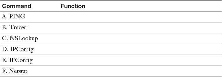
1. Traces data route (hops) between routers
2. Displays information about the default DNS server
3. Linux and OS X command that displays IP configuration information
4. Tests connectivity between hosts on a network
5. Displays IP address and domain name of a remote computer
6. Displays a computer’s IP address, subnet mask, and default gateway
24. When your tablet or smartphone does not get a clear cellular signal, which of the following steps could improve the signal? (Choose two.)
A. Turn off Wi-Fi.
B. Change the angle of your screen.
C. Reset your cellular settings to a faster 802.11 specification.
D. Use the slider switch on an iOS device to fine-tune reception.
25. Which of the following steps could help increase the battery life on your mobile devices? (Choose two.)
A. Don’t overcharge.
B. On iOS, turn on the background app refresh.
C. Use the iOS slider switch to shut down weekly.
D. Wait until almost out of power before recharging a device.
26. Vertical streaks extending down each page printed by a laser printer usually indicates which of the following problems?
A. Low toner
B. A dirty print ribbon
C. Damaged ink nozzles
D. Damage to the imaging drum
27. Smudged print from an inkjet printer could be caused by which of the following?
A. Printheads or rollers are dirty
B. Fuser does not reach a high enough temperature
C. Photosensitive drum is not properly charged
D. Toner cartridge needs to be replaced
28. If toner can be brushed off the page after printing, which component of a laser printer is malfunctioning?
A. Print drum
B. Fuser
C. Paper feed rollers
D. Corona
29. If a document requires the maximum amount of memory that is available to a laser printer, the printer might attempt to compress the document. Which of the following statements best describes the result of this compression on the final print page?
A. Some text could be lost.
B. The printed text may be cloudy.
C. The print process will be slower.
D. Some pictures could be deleted.
30. Which of the following print tools is used to manage and maintain print jobs?
A. Print spooler
B. Fuser
C. Printheads
D. XPS Document Writer
Answers and Explanations to Hands-On Labs
Lab 13-1: Beep Codes, Fans, Multimeter, and Hard Disk Testing
Almost all computers will beep when either memory or video is missing. However, if you need to attach a speaker, search for “PC motherboard internal speaker” or “mainboard internal speaker” at major computer parts online stores to find a single piece or bulk pack.
Most fans for current systems are 120mm or larger. Be sure to choose a ball-bearing model; sleeve-bearing fans wear out prematurely.
If you are testing a Dell computer’s power supply, keep in mind that many models of Dell computers do not follow the ATX pin out. Look up your model to determine which pinout to use as a voltage guide.
Seagate (SeaTools), Western Digital (Data Lifeguard Diagnostics), and HGTS (WinDFT) all offer downloadable drive testing apps. Samsung and Maxtor drives use Seagate SeaTools.
Lab 13-2: Network, Mobile Device, and Printer Troubleshooting
Tracert may display as many as 20 hops or more to the website (URL) or IP address of a remote computer.
The Windows troubleshooters have improved tremendously in recent years, although they are not infallible.
For the most comprehensive view of your network connections from a Windows computer, use Ipconfig /all.
If you use a computer’s USB port to charge your devices, use the special USB charging port if available on your system.
Laser printer cleaning sheets and inkjet printer cleaning sheets are available at most office supply stores.
Make sure all inkjet printer cartridges have plenty of ink before using the head-cleaning feature. Use it only if the nozzle check indicates some nozzles are clogged, as the cleaning process uses up ink.
Answers and Explanations to Review Questions
1. D. Reboot the computer and open the BIOS/UEFI menu. Check the BIOS settings for the CPU temperature. As a technician, you should be very familiar with all of the diagnostic information that is available in the BIOS.
2. A. A checksum error is generated when the CMOS settings have failed, either because they have been erased or because the CMOS battery has failed. If you see a checksum error message, acknowledge it and allow startup to continue. The system will load using the default BIOS settings.
3. A, B, D. POST checks the memory, keyboard, hard drives, and other essential hardware. The mouse is not considered to be essential to the operation of the computer and is not checked by POST. If POST finds any problems it reports those problems as error messages during startup.
4. D. When the clock and calendar on your computer are no longer able to keep accurate time, this is an indication of a failing CMOS battery.
5. B. This is a CMOS battery, which provides a constant source of electricity to the CMOS chip to maintain the CMOS programming.
6. A. The automatic reboot option is configured in System Properties on the Advanced tab under Startup and Recovery.
7. A. North America uses 115 volts. Europe and Asia use 230 volts.
8. D. These components are capacitors. Capacitors store an electrical charge and can deliver a painful and even dangerous shock if accidentally discharged.
9. C. A multimeter is used to test AC or DC voltage, continuity, resistance, and amperage. A loopback plug is used to test ports. PING is a network diagnostics program. A tone generator is used to test network cables.
10. A, C, D, G, H. A power supply should produce +3.3, +5.0, -5.0, +12.0, and -12.0 volts.
11. B. A loopback plug is used to test ports. You can attach a loopback plug to a port and run diagnostic programs to make sure that the port receives the same characters it sent.
12. C. A POST card is a device that detects the hexadecimal code produced by the BIOS during startup. These codes may be used to diagnose problems that are not necessarily reported by POST beep codes or screen messages.
13. D. This jumper forces the SATA drive to run at a slower rate to make it compatible with older host adapters.
14. A. Reboot the computer and access the BIOS startup program. Reorder the boot sequence and save the changes. Changes made to the BIOS configurations are saved on the CMOS chip.
15. C. S.M.A.R.T. refers to Self-Monitoring Analysis and Reporting Technology, which detects problems with and warns of failure of internal magnetic hard drives.
16. D. Normally, when you delete a file, it is not really deleted; it is moved to the Recycle Bin and may be recovered if you change your mind. If you press Shift and Delete at the same time, you will permanently delete the file.
17. B, C. Both Defragmentation (defrag) and error-checking (CHKDSK) can be accessed through the drive properties or from the command line.
18. A. VGA mode uses low resolution (640 x 480 on Windows Vista/7) with minimum colors and basic drivers and is used when troubleshooting display problems. A Windows system starts in VGA mode if Low-resolution mode or Safe mode has been selected at startup or if the correct drivers are not available.
19. A, D. If an LCD display is flickering, the most likely cause is a failing backlight or inverter.
20. C. Burn-in, the persistent display of a “ghost” image on-screen that was displayed previously, even after the current screen contents have changed, can affect both LCD and plasma displays. On an LCD display, it is frequently caused by stuck pixels.
21. B. A DHCP server is responsible for assigning IP addresses on a network. If valid IP addresses are not available, APIPA (169.254.x.x) addresses will be assigned. If your network is using APIPA addresses, you should add additional valid IP addresses to the DHCP server.
22. D. A crimper is used to attach coaxial, RJ45, or RJ11 connectors to network cables.
23.

24. A, B. Some cellular connections do not work well if Wi-Fi is enabled, so if you are having problems getting a clear cellular signal, you should disable your Wi-Fi connection. You should also try rotating your screen because the antenna is located around the periphery of the screen casing. 802.11 is a Wi-Fi specification. The iOS slider switch does not affect reception.
25. A, C. You can increase your battery life by not overcharging and by shutting down an iOS device weekly with the slider switch.
26. D. Vertical streaks that show up on every page printed by a laser printer usually indicate damage to the imaging drum. Low toner might cause uneven printing. A dirty print ribbon could create problems on a thermal printer or an impact printer. Damaged ink nozzles would be a problem on an inkjet printer.
27. A. Clogged or dirty printheads and rollers on an inkjet printer can cause smudging of the printed page. Fusers, photosensitive drums, and toner cartridges are components of a laser printer, not of an inkjet printer.
28. B. The fuser is responsible for heating the toner and pressing it into the paper. Brittle or flaking toner is indicative of a failing fuser.
29. C. Compressing the data in a print job takes time and that may make the print job slower.
30. A. The print spooler stores print jobs in a queue and releases the computer to perform other tasks while the spooler manages the print job.