
Chapter 11
Transmission of Compressed Medical Data on Fixed and Mobile Networks
11.1. Introduction
An objective of the present chapter will have to be a detailed discussion about the aspect of medical data diffusion (broadcasting or transmission). This encompasses access to medical information, by fixed networks (wired Internet, for example) or mobile networks (wireless communication) or a combination of both fixed and mobile networks (called hybrid networks).
There are numerous situations where this type of information exchange can be encountered, either for remote consultations inside buildings, or outside, or combining the two environments, or even for ambulatory assistance, under the same conditions of geographical variability.
The main difficulty in transmitting such compressed data results from the highly fragile nature of the data. This fragility can arise due to perturbations, which can happen during the transmission, because of errors, packet losses, etc.). At the same time, there can be several other causes of uncertainty in the data. These may arise, for example, as a result of compression techniques, which can also integrate the watermarking phase, or due to the choice of modulation technique, once the bit stream is obtained, from the random access procedure (degradation, unguaranteed rate, etc.), routing, etc. At the end of the chain, a process of quality assessment (as described in Chapter 5) will be carried out, as a function of the usage, to discern whether the received signal is acceptable.
The chapter is organized as follows. A brief overview of the existing applications based on the transmission of medical data is presented in section 11.2. This section also highlights the difficulties associated with these methods and the difficulties that may arise in immediate future. Section 11.3 will describe the various networks employed to tackle these situations, with their various specificities and sensitivity to the perturbations. Section 11.4.1 will present a set of existing or possible applications, using the fixed and mobile networks and in section 11.4.2 the effects of the errors or losses on medical images, for various standards of compression techniques, will be demonstrated. Section 11.4.3 will present the effect of the use of usual error correcting codes, at the cost of increased redundancy for the information transmitted. We shall also introduce the Mojette transform in this section, along with its application within the domain of medical data n networks. The chapter will be concluded with a discussion of the problem of joint source-channel coding in the context of medical data.
11.2. Brief overview of the existing applications
If the first objective in the communication of medical data is transmission, then the second one is access to the archive or files. it is a well known fact that, with the ever increasing quantity of data, compression becomes necessary.
Sometimes at high rates, the coding procedure may make the information fragile, particularly for an information system environment which is not that robust, either inside the same hospital service or between several services. The “direct access” aspect of the information, from the compressed data, has been mentioned in the preceding chapters and is mentioned in the following discussions. There exist many applications, which are based on medical data transmission. The domain of telemedicine is often mentioned in the same category, if it is a question of exchanging medical data using a simple e-mail.
Generally speaking, the optimal functions of the exchange of messages, files and the sharing of peripherals or even the access to a sophisticated information system, are yet to come into prominence.
Table 11.1 summarizes the existing applications and specifies, for each one, the temporal constraints in terms of transfer of information delay.

Table 11.1. Existing medical applications and associated temporal constraints
11.3. The fixed and mobile networks
In this section, we briefly present the wired and wireless networks, as well as their operating modes, with descriptions of the various stages of the transmission chain for the two cases. These two types of communications can also be mixed together (in hybrid networks) and they are discussed in section 11.3.2.
11.3.1. The network principles
11.3.1.1. Presentation, definitions and characteristics
In the early 1980s, the beginning of the interconnection required a consensus among manufacturers to enable the interoperability of equipment. In this context, the International Organization for Standardization (ISO) proposed a layer structure of any exchange of data within a computer network using its OSI (Open System Interconnection). Today, this model, which was imposed as a reference in the world of computer networks, also unifies the telecommunication community and the information processing community. Rather than subdividing the activities into different subcategories, it offers a practical conceptual field because of its simplicity in designing systems, involving the relations across different layers. Figure 11.1 summarizes the design from the interface user (level 7) up to the binary transmission (level 1).
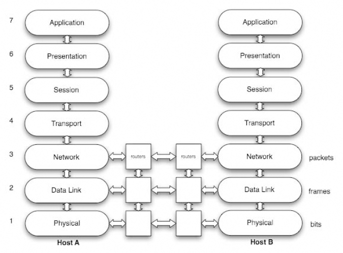
Figure 11.1. OSI model in 7 layers of two interconnected hosts A and B. The transmission units of layers 1, 2 and 3 are specified on the right of the figure
In a simple manner, this model can be divided into two categories respectively grouping the applicative layers (levels 5 to 7) and the transport layers (levels 1 to 4). Independent of the temporal constraints mentioned in Table 11.1, the applications are classified according to their mode of information exchange. The types which have become popular in recent times are “client/server”, “push”, “flow” and “peer-to-peer”.
The transportation of information (as shown in Figure 11.1, from levels 1 to 4) is characterized by a fragmentation of the initial volume of information into a series of packets. This mode of transport is different from the continuous flow of data in the commutated circuits, for example, the commutated telephone network. The autonomy of each packet containing a source address and a recipient address authorizes the multiplexing of several users on the same connection and therefore, increases the transmission rates. This same autonomy brings flexibility in the routes through which the packets transit. The routers, as points of interconnection, determine the optimal routes, depending on the state of the network and recopy the packet of a connection to another one. As an after-effect of this process, the multiplication of the paths generates delays, which in turn causes jitters and even the loss of packets with quite significant effects on an initial volume of information weakened by fragmentation. This chapter will make a detailed analysis of the practical impacts of these parameters of quality of service.
11.3.1.2. The different structures and protocols
In practice, the Internet, functioning with two protocols of level 3 and 4, is itself imposed. At level 3, the Internet Protocol (IP) manages the interconnection networks. Devices called routers interconnect the networks. They analyze the recipient's address in the header of each packet in order to perform the delivery. Two cases usually occur in packet processing, either the router knows the recipient address for a direct delivery or the router does not know the recipient and leaves the task to its default router. At level 4, the TCP (Transmission Control Protocol) involves a connection between the transmitter and the receiver of the packet. It exercises the control and maintains the reliability of the transmission by adjusting its emission rate to the network capacity, by detecting and performing the retransmission of lost packets.
This mode of operation is prohibited for applications sensitive to delays such as telesurgery. In this context, the transport protocol UDP (User Datagram Protocol) is used by acting without connection and without retransmission. Additional mechanisms are needed in this case to increase reliability.
The lower layers are responsible for the transmission of data by adapting themselves to the specifications of the physical medium. Each of these protocols leads to the definition of a format of a particular frame and to a specific address (in the network the IP protocol's role is to erase these specifications). In fixed networks, Ethernet connections are widely deployed. With recent developments, there have been widespread modifications of its use. Although the initial range of a local area network was about 2.5 km, nowadays its use is often limited to a floor of a building (a range of about 25 to 100 m) with a star topology, involving an active repeater type central element (called a “Hub”) or switch. Thus, it has been possible to increase the rates to about 100 Mbits/s for fast Ethernet and 1 or 10 Gbits/s for gigabit Ethernet networks. The use of optical fibers facilitates the construction of intra-hospital networks.
11.3.1.3. Improving the Quality of Service
The interconnectivity offered by the IP comes at a price. The optimality in the routing algorithms, the relative reliability of transport protocols or even the limited capacities of processing the interconnected nodes lead to delays of transmission, weakening the Quality of Service. To prevent this, two actions are possible, either taken in the heart of the network, or at the terminals. The construction of a network that is capable of applying an intelligent management distinguishing stream or the classes of priority services, is the goal of the “IntServ” and “DiffServ” working groups of the IETF (Internet Engineering Task Force) [BRA 94], [BLA 98]. These approaches assume an end-to-end implementation, which becomes particularly difficult for a wide area network.
The action at the source or destination requires simply a network that is doing its best, e.g. “Best Effort”. In this context, coding with unequal error protection (UEP) is tested today. Contrary to the separation principle (source coding then channel coding), this protection mode considers a coding of a distinct channel for each priority of the source as a function of the channel status. This approach offers good reactivity for no stationary channels in mobile networks. It is facilitated by the developments of the scalable representations of multimedia information (JPEG 2000 for still images or MPEG4/H.264 SVC for video images). Overviews of advanced protection are available in [GOY 01] and [HAM 05]. At the end of the chapter, an example of UEP implementing a function of discrete tomography is detailed.
11.3.2. Wireless communication systems
11.3.2.1. Presentation of these systems
Wireless communication systems can be characterized according to the context of their use (inside/outside of buildings, range, etc.) and their rates, i.e. implicitly by the proposed services. A considerable evolution of the wireless system has been observed during the last 20 years. Some key elements of this development are mentioned now. At the beginning of the 1990s, standard GSM (Global System for Mobile) systems, functioning digitally at frequencies of 900 and 1,800 MHz, were deployed in Europe. They allowed the transmission of vocal communications and reached rates close to 9.6 Kbits/s.
At that time, they provided a national coverage initially centered on large cities and highways. Gradually, this coverage extended to almost the entire territory and the network became denser in order to increase its capacity in zones with strong traffic. Since 2000, we have experienced an explosion in the standards and proposed services. Indeed, it is no longer only a question of transmitting voice by radio channel, but also of implementing wireless computer peripherals, exchanging computer files, images and, more recently, video.
We can globally classify these wireless systems in three large families: personal networks (WPAN: Wireless Personal Area Network), local networks (WLAN: Wireless Local Area Network) and metropolitan networks (WMAN: Wireless Metropolitan Area Network). For the WPAN, the principal standard is “Bluetooth” to ensure short range connections between peripherals and computers, for example.
We should also mention “Zigbee” which is a recent technology, characterized by data exchanges of low rates and small consumption for networks of sensors for instance. Concerning the WLAN, the norm IEEE 802.11 called Wi-Fi and all its developments in both present and future use (IEEE 802.11a, b, g, n) represent the main system. They allow information exchange with high rates inside a building within an infrastructure or not, i.e. with or without a fixed access point to a core network.
As an example, the characteristics at the level of the physical layer are 54 Mbits/s for the standards a and g and 100 Mbits/s at the level of the data link layer for the standard n which is based on MIMO (Multiple Input Multiple Output) technology.
In 2003, within the WMAN family, two major evolutions to the GSM standard took place: the GPRS (General Packet Radio Serviced qualified for 2.5 G development and the EDGE (Enhanced Data rate for GSM Evolution) associated with a 2.75 G development. Both transmit with a packet mode, like the fixed networks, contrary to the GSM which used a circuit mode. With this main change, GPRS is able to reach net rates ranging around 20 to 30 Kbits/s and the EDGE, net rates around 150 to 200 Kbits/s. These developments, however, do not replace the whole generation.
The third generation (3G) is currently making its appearance. The UMTS (Universal Mobile Transmission System) standard represents an important technological advance because it can transmit much more data simultaneously and should offer a significantly higher rate than those of the previous generations.
This standard is based on the spread spectrum technique called the W-CDMA (Wireless Coded Division Multiple Access) [PRO 00]. It uses the frequency bands located between 1,900 and 2,200 MHz. In theory, it can reach 2 Mbits/s in a fixed environment and 384 Kbits/s in a moving environment. These increased speeds of data transmission enable the provision of new services: visiophony, mobile television, etc. The UMTS is also sometimes called 3GSM, thus underlining the interoperability which was ensured between the UMTS and the standard GSM, which it succeeds.
Finally, we should point out that a specific concept related to non-fixed infrastructure is currently being developed in Europe. It mainly concerns ad hoc networks, also known as auto-configurable networks.
In practice, various applications are possible, such as intra-vehicle communications or sensor networks (see section 11.4.1). However, whatever the considered wireless system of communication, the multi-path phenomenon of the transmission channel introduces significant constraints. In addition, we must note that this aspect does not concern fixed networks.
11.3.2.2. Wireless specificities
The main difference between fixed and mobile networks lies in the physical layer (see Figure 11.2) and more precisely in the transmission channel.
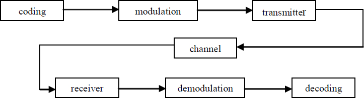
Figure 11.2. Scheme of the physical layer of a wireless system
Let us briefly recall the objectives of the various elements of this chain of transmission:
– the coding is decomposed into two operations, the source coding where the objective is the compression of the information, and the channel coding where the goal is to improve the robustness of the compressed signal of the information with respect to the perturbations which it can undergo during its transmission. The principle of the channel coding consists of introducing redundancy, allowing detection and errors correction of bits (described in detail in section 11.4.3.1);
– the modulation is designed for two purposes. Firstly, it ensures the transposition in frequency of the information, and, secondly, it transforms the digital information in an analog signal, which can be sent to the antenna for emission. The principle consists of assigning an amplitude and a phase of an analog signal, to a symbol, as illustrated in Figure 11.3. This figure presents a digital constellation (i.e. representation of a signal in a complex plan) for a Quadrature Amplitude Modulation with 16 states: 16 QAM;
– the radioelectric channel is the medium of transmission which allows the transfer of information between a transmitter and a receiver. Its principal property is the mechanism of multipath trajectories which governs the propagation of the radio waves;
– the digital reception ensures the synchronization and the recovery of rhythm, which facilitates the operations of demodulation and decoding;
– the demodulation and decoding perform the dual operations of modulation and coding.

Figure 11.3. Digital constellation of a 16 QAM modulated signal under ideal conditions
In this context, special emphasis should be placed on the fact that the channel coding and the modulation are two key elements for the performances of the physical layer. These performances can be defined in different ways, where each of these constitutes a trade-off between the rate and the robustness of a transmission. Transmission performances can also be evaluated using the concept of Quality of Service, which relates to the upper layers of the OSI model. As mentioned above, the main specification of wireless systems compared to wired networks is located at the channel level. This presents spatio-temporal variability which does not exist for wired networks. There are two types of variations: slow variations due to the mask effects, such as an obstacle between the transmitter and the receiver and fast variations related to the multipath trajectories which characterize the channel. This phenomenon corresponds to the fact that a wave generated from a source generally follows different paths before reaching the receiver (Figure 11.4).

Figure 11.4. Principle of the multipath trajectories mechanism and its consequence on the received signal
Each path followed by the wave is characterized by a series of interactions with the environment of propagation, which are mainly related to the phenomena of reflection on surfaces, refraction through walls and diffraction from obstacle edges [VAU 04]. The received signal is a combination of all the propagated waves. This combination creates interferences which sometimes provide deep fading out of the reception level or frequency selectivity. This explains how the multipath phenomenon of the radio-electric channel generates perturbations during the signal transmission at a given time, a position and a frequency (section 11.4.2.2.1).
Various approaches exist to model the behavior of such a channel. They can be stochastic or deterministic [ISK 02] [VAU 04] [COM 06] but they are all based on the experimentation and/or the simulation related to the electromagnetic waves propagation. The statistical channel models generally used are those by “Gauss”, “Rice” or “Rayleigh”. These models aim to define the variations of the magnitude of the received signal and sometimes the phase.
The Gaussian channel model consists of adding a Gaussian white noise to the received signal; this noise is assumed to represent all the perturbations that influence the signal during its transmission.
The Rice model is used when one of the received paths is dominant. This is generally the case when the transmitter and the receiver are directly visible. The magnitude S of the received signal can be obtained from the following probability law:

where I0 is the first type Bessel function of zero order, A is the magnitude of the dominant wave and σ2 is the total power of the signal. The phase can be considered as constant or variable according to a uniform probability law.
In the case where none of the paths is dominant, the Rice model can be replaced by the Rayleigh model, defined by the following probability law:

Moreover, it is also necessary to note the possible occurrence of the Doppler phenomenon when the transmitter and/or the receiver are moving. This phenomenon induces frequency shifts in the transmitted signals, directly related to the speed of movement, the carrier frequency and the directions of arrival of the waves, with respect to the direction of moving. As an example, taken from the acoustic field, let us consider an ambulance siren, which is perceived differently as it passes by an observer.
In general, in digital transmission, the channel study leads to characterizing it, in order to facilitate the setting up of appropriate techniques for formatting and restoration of the information. As an example, let us consider the dispersion of the propagated path delays whose value gives an indication of the risk involved in the interferences inter symbols.
11.4. Transmission of medical images
11.4.1. Contexts
Let us consider at least three different geographical contexts or situations.
11.4.1.1. Transmission inside a hospital
This considers transmission inside a hospital on fixed networks or hybrid networks with a low mobility. The methodologies of remote image reading using fixed networks inside the same service are already well developed. We can consider as an example of hybrid networks employed in this geographical context, the access to the medical data at the patient's bedside in his hospital room, at the time of the physician's visit; this using a simple notepad.
11.4.1.2. Transmission outside hospital on fixed networks
Traditionally, this context relates a hospital service to the outside world (to a medical doctor or specialist, other hospitals, etc.). For the purposes of telemedicine, specific architectures are proposed for an optimal exchange of all the information which can be useful for the diagnosis, including the hierarchical coding of the image, the inclusion of meta data suitable for the acquisition or the history of the image and the modes of interaction with these data. This is why part 9 of the JPEG 2000 standard extends the concept of the image compression system to a real communicating multimedia system. JPEG 2000 Interactive Protocol (JPIP) specifies the interactions with the elements constituting the JPEG 2000 stream (component, quality layer, levels of resolutions, regions of interest, metadata, etc.) (Figure 11.5). JPIP is based on a client/server type of architecture. It is really the stream structure, which ensures the availability of the medical data for the client. By authorizing a remote consultation of a very large image – a size of 64K×64K pixels is allowed – even on channels with a very small capacity, this protocol is well suited for transmissions outside the hospital on fixed networks. With its recent integration within the DICOM standard, it can be safely assumed that JPIP is going to be implemented rapidly in the near future, in hospital centers and for remote access.

Figure 11.5. Client/server in JPIP (JPEG 2000 Interactive Protocol) [TAU 03]
11.4.1.3. Transmission outside hospital on mobile networks
These situations will arise where emergency intervention is required to diagnose an injured patient by a medical team, where medical assistance is available at some distance and the environment is quite complex (e.g. involves a complex road network, a mountainous zone or sea navigation, etc.).
11.4.2. Encountered problems
Under these transmission modes, a very important factor to be considered is the loss of information. In these situations, the network layer of a fixed infrastructure or the physical layer of a mobile network can be considered as the origin. There can be two main types of impact on the data stream.
11.4.2.1. Inside fixed networks
In fixed networks, the loss of packet takes place quite frequently. Currently the packet losses reach more than 5%. These losses can be primarily attributed to the saturation of intermediate equipment as routers and secondarily to parasitic errors in the transmission line (due to interferences, breakdowns, etc.). Inside routers, queue management is generally beyond repair: in fact, the impact of overload can fatally lead to the suppression of packets.
The simplest of these mechanisms is called Random Early Detection (RED). Its name is due to its prevention inside routers. The principle is to put a probability of packet dropping as soon as a minimal threshold of filling is reached. This probability varies linearly according to the filling until a maximum threshold is reached, that occurs under the condition when the queue reaches saturation. If the maximum threshold is reached, the suppression is systematic. Figure 11.6 shows this scheme for preventive management.
These bottlenecks also have an impact on the delay (although their effects are not that severe and they are not beyond repair) and this gives rise to a phenomenon called jitter, which results from the variations between transmission delays.
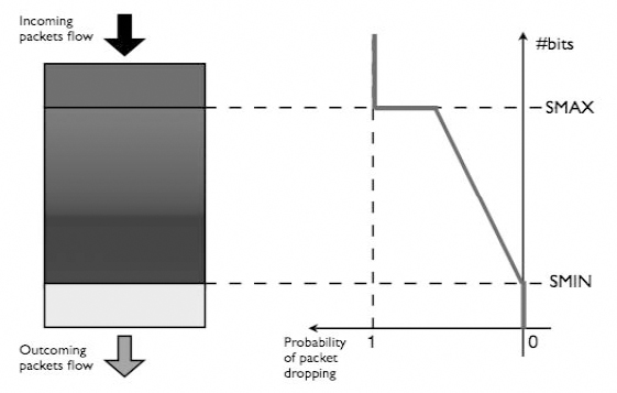
Figure 11.6. RED queuing algorithm. The probability of packet dropping is a function of filling. Below SMIN, no packet is dropped. Between SMIN and SMAX, the probability increases linearly (random early discards). Above SMAX, all incoming packets are dropped
11.4.2.2. Inside mobile networks
11.4.2.2.1. Difficulties induced by mobility: some errors
As was indicated in section 11.3.2.2, the transmission channel experiences several effects: slow and fast variations from one side and the Doppler shift from the other side. These effects have different consequences on the transmission quality.
The slow variations generated by the masking effects leads to a received power which can get considerably weakened during a relatively long duration. This generates losses by burst during a transmission.
The fast variations due to the multiple path phenomenon induces relatively isolated errors. In fact, it is shown that the deeper the fading the rarer they are [LEE 93]. For example, a fading of 10 dB has a probability of appearance of 10% in time or space, whereas a fading of 30 dB has a probability of only 1%. However, whatever the nature of variations, the degradation of the received power involves a contraction of the digital constellation associated with the received signal (Figure 11.7a).
As far as the Doppler effect is concerned, the Doppler shift leads to a rotation of constellation at a frequency corresponding to this shift (Figure 11.7b). In order to determine the value of the symbols, i.e. to demodulate, it is thus necessary to remove this rotation first.

Figure 11.7. Examples of perturbations of the digital constellation of a 16 QAM modulation (Figure 11.3) induced by the channel: (a) contraction due to a fall of the received power; b) rotation due to the Doppler effect
In recent systems, the techniques implemented against all these channel effects in time and in space, are based on the estimation of the channel.
There are several techniques. At the emission, for example, a pre-coding of the information can be carried out and at the reception, an equalization [PRO 00] approach is often applied.
11.4.2.2.2. First tests and report
Let us now consider two types of channel models, presented above: the Gaussian channel model and the Rayleigh channel model. The perturbations in the channel can be measured in terms of Binary Error Rates (BER) and the quality of image can be measured in terms of PSNR. The compression rate is noted as CR = n:1 for a rate of n.
Let us first consider an MRI 256×256 image, compressed by the JPEG and JPEG 2000 standards, which shows the considerable fragility of these two standards, even under the situations of small perturbations in the transmission channel (Figure 11.8).

Figure 11.8. Example MRI images reconstructed after transmission via a Gaussian channel with BER = 2.49.10−4. (a) Original image; then compressed with CR = 5.6:1, by a JPEG coder (b) and a JPEG 2000 coder (c)
In the case of images using DICOM, Figure 11.9a shows the average values of the PSNR of the images which can be reconstructed via a Gaussian channel, where the BER is varied. For a BER higher than approximately 1.5.10−4, the decoding of the files achieved, with DICOM format, appears to be impossible.
The BER limit value of about 10−6 was found as being an acceptable binary error rate in order to be able to receive the image without error on this type of channel. Thus, beyond this limit, and under a BER value of about 10−4 (Figure 11.9a), and if the files can be opened at the receiving end, the received image inevitably contains some errors.
As an example, in Figure 11.9b, we show an image received with a BER equal to 5.38.10−5, i.e. with a PSNR = 47.79 dB. We can actually identify the appearance of artefacts in the image, as shown in Figures 11.9b and 11.9d (which shows the zoomed area of a corrupted zone). This may actually lead the doctor to make the wrong diagnosis or conclusion.
In Figure 11.10, we consider several cases of transmission in the Rayleigh channel for the same radiographic image (of size 440×440 pixels) for various BER values and a compression ratio CR = 10:1, with JPEG and JPEG 2000 coding.
We have observed in these tests (with CR = 10:1) that, for the JPEG standard, it is not possible to perform a diagnosis of the reconstructed image for a PSNR below 26 dB. Beyond a negligible BER value of 3.10−7, the JPEG will not allow a diagnosis of the reconstructed image (for PSNR ≤ 26 dB). Regarding the JPEG 2000, this standard is always more robust than JPEG in term of the PSNR values.
For JPEG 2000, Figure 11.11 shows the reconstructed image after transmission with BER equal to 1.57.10−5, and a PSNR value of 39.73 dB, via the same Rayleigh channel.
All these tests show the vulnerability of the coders to transmission errors, and justify the introduction of a strategy for the protection of the information to be transmitted.

Figure 11.9. Average behavior of DICOM (a) during transmissions by Gaussian channel of the MRI image shown in (b) with BER= 5.38.10−5. (c) and (d) are the zooms of the left lower part of the original image and image (b) respectively

Figure 11.10. (a) Original image of thoracic radiography compressed with JPEG and JPEG 2000 at a compression ratio CR = 10:1, and (b) transmitted in a Rayleigh channel: variation of the PSNR as a function of the BER
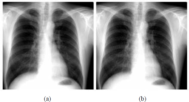
Figure 11.11. (a) Compressed image with CR = 10:1 according to JPEG 2000; (b) reconstructed image via a Rayleigh channel with BER = 1.57.10−5
11.4.3. Presentation of some solutions and directions
In transmission, the error correcting codes are generally used for the purpose of protection. In the case where the protection is restricted to one data flow, we can thus consider an equal protection. On the other hand, unequal protection can be considered as soon as the priorities are defined for each flow [ALB 96].
Moreover, by adapting the protection to the characteristics of the transmission, the BER can also be significantly reduced, while preserving an optimal useful flow.
11.4.3.1. Use of error correcting codes
There is a great number of Error Correcting Codes (ECCs). Among the different classical codes, we can specifically mention the linear block codes, the convolutional codes (e.g. [SOU 04] described the behavior of these 2 classes in terms of BER and SNR on Gaussian or Rayleigh channels), cyclic codes [DEB 00] and the turbo codes [BER 93]; for a more exhaustive list, see [MAC 04] or [LIN 05].
Let us recall that the principle of a correcting code is to introduce redundancy into the transmitted signal. Thus, this redundant information is used at the moment of reception to detect and correct the isolated errors or an entire data packet.
For each ECC, a certain number of characteristic parameters are defined. Therefore, if coding consists of associating with a given information word of length k, a word of the code of length n, such that (n > k); thus the rate Red = (n-k)/k expresses the rate of the introduced redundancy. The efficiency of the code is characterized by the ratio R = k/n. The error correcting capacity, denoted t of the code is defined using a distance of dissimilarity, denoted d between two code words (e.g. the Hamming distance). Generally, d ≤ n-k+1.
Among the cyclic codes, the RS (Reed-Solomon) codes [REE 60] are intensively used. They have the property of coding M-ary symbols. By this grouping of binary characters, the RS codes correct the arriving errors in burst mode. The distance between the words of codes is maximal, namely: d = n-k+1. This allows maximizing the correcting capacity. Therefore, these codes are optimal or MDS (Maximum-Distance Separable).
In the following, these codes are denoted RS (n, k).
11.4.3.1.1. Equal protection using Reed-Solomon codes
We have chosen the classical codes RS (255, k), which are well known for their use in spatial communications. Here n = 255 = 28 -1. The source symbols are the coefficients of a Galois field polynomial of dimension 256 [RIZ 97], and t (with: t = (255-k)/2) is the capacity of correction allowed by the codes. Table 11.2 indicates, for both an MRI image and a thoracic radiography image (shown in Figure 11.8 and 11.10, respectively), the effect of adding a RS (255, k) code on the compressed image (size expressed in Kbytes) and on the other hand, its efficiency denoted R. We must note that the considered images are encapsulated in DICOM format.
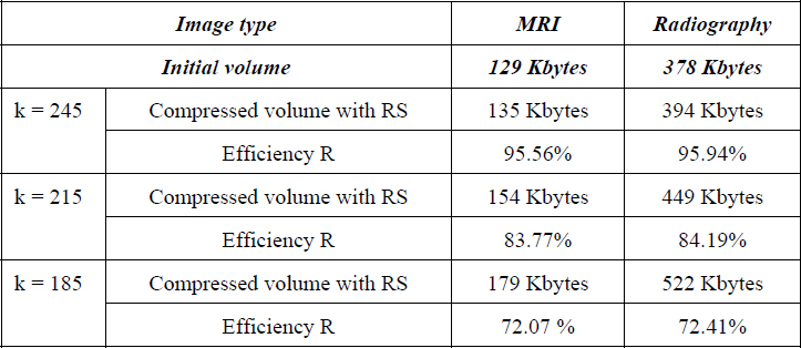
Table 11.2. Effect of adding a RS (255, k) code
If these correcting codes are applied to the whole MRI image (i.e. equal protection), a bounded (i.e. limited) BER is thus obtained, as shown in Table 11.3. This allows a perfect image reconstruction according to the Red redundancy rate. In addition, we consider here that the transmission is performed through a Gaussian channel.
That means, for example, that the RS (255, 225) code can correct the errors of the channel up to a BER of the order of 3.10−3, for a data redundancy cost of 13.33%. Beyond that, the reception systematically includes errors. Consequently, for a BER higher than 1.8.10−2, no correction is possible whatever the rate of redundancy.
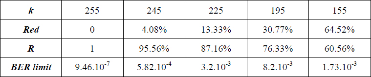
Table 11.3. Acceptable BER limits when adding RS (255, k) code on the DICOM MRI image of Figure 11.9
We can also display the results using a limit curve. We thus obtain on the “colon” image shown in Figure 11.12a, the BER limit curve corresponding to an error-free reception with respect to the Red rate (Figure 11.12b).

Figure 11.12. (a) Colon image; (b) curve of maximal BER with respect to the redundancy rate for an error-free reconstruction
Finally, it should be noted that allowing a higher priority to the header of DICOM data, does not allow any additional improvement regarding the robustness related to the image.
11.4.3.1.2. Towards a content-oriented protection
The main limit of equal protection is that the reconstruction is “all or nothing”. This leads to the idea of a content-oriented protection of the data where the reconstruction is more progressive. Moreover, it is clear that if we protect certain parts of the transmitted file, we may improve the performances in terms of global redundancy.
A first idea consists of using a fixed length binary encoder for high priority data. The results of simulation show a significant resilience to the errors, with a small efficiency loss. This supposes the use of scalable source encoders like the ones allowed by JPEG 2000, SPIHT, LAR (see Chapter 7) or some video encoders such as MPEG and H26x. Closer to the content, the Forward Error Correcting codes (FEC), which include a scalable protection of the source, have also been introduced. For example, Mohr et al. [MOH 00] use SPIHT source encoding, coupled with RS codes for a packet correction on both ATM transmission and MRI images. Likewise, signals with temporal constraints (e.g. video) can be coupled with RS codes having different correction capacities. This unequal protection allows a gain of expected quality at the reception, which is not negligible with respect to an equal protection. The Mojette transform also handles this unequal protection, which is particularly well suited to overcoming the problem of packet loss experienced on some networks by significantly reducing the complexity.
11.4.3.2. Unequal protection using the Mojette transform
The Mojette transform [GUE 05] is a discrete and exact Radon transform. While its original use relates to tomographic reconstruction, it also presents good properties to ensure the integrity of data during a transmission on unreliable networks. In fact, it enables the easy representation of information by a set of redundant 1D projections. An example of this representation is given by Figure 11.13.

Figure 11.13. Mojette transform of a 4x4 image. Projections (-2, 1), (1, 1) and (1, -1) are represented. Each element of projection results from the sum of the image elements in the direction of projection. In this example, the modulo 2 addition (XOR operator) is used
These projections are regarded as many transport units (packets) whose loss or misordering does not disturb the reconstruction of the data at reception. From an encoding point of view, the 2D support of the information acts like a true geometrical buffer memory in the sense that the data flows using this support from which projections are calculated. By varying the number of projections necessary for the reconstruction of a geometrical buffer memory, it is possible to protect hierarchical information in an unequal way. Within this context, all projections are equivalent in terms of reconstruction. Progressive decoding of information is supported by an unequal number of received projections. For example, the low resolution of an image may require a low number of projections in order to be reconstructed (i.e. supporting a high rate of packets loss), whereas higher resolutions will require a greater number of projections. This mode of representation allows us to support variable rates of redundancy, depending on both the priority of the information and the status of network.
In this way, any source encoder having a scalable output representation can be protected. In [BAB 05], an unequal protection of lossless LAR encoder is carried out. In addition, an efficient comparison to the approaches proposed in section 11.4.3.1 has been performed. A number of projections are optimally allocated for each resolution of the encoder, depending on the quality of the image and of the characteristics of the transmission channel. The model of packet loss follows an exponential law here (i.e. the average value of the losses is given by parameter μ of the law). The progression of decoding depends on the number of projections received, in a deterministic way. A set of mt projections out of N is sufficient to reconstruct the resolution i. An example of encoding is illustrated in Figure 11.14. The unequal protection is applied to an angiography transmitted through a channel where μ = 10%. The curve indicates the expected qualities in terms of PSNR at the reception taking into account both the source and the status of the channel. To each rate corresponds the optimal protection of the 6 levels of resolution delivered by the encoder. The singularities correspond to the decision of the system to send an additional flow in order to reach the available maximal quality according to the available rate. For example, to reach a quality of 38.51 dB, the 6 resolutions must be transmitted; for N = 16 projections: 8, 12, 13, 13, 15 and 16 projections are respectively necessary for the reconstruction under the conditions of transmission. For comparison purposes, the analysis rate-distortion for RS codes coupled to LAR is also given in Figure 11.14. For better comparison legibility, only the range of 0-5 bpp is displayed. On average, an overhead of 2.78% is recorded for Mojette encoding in this example, but for a complexity which is linear with respect to the number of pixels and the number of projections. Moreover, the increase in the data amount or the rate of loss, contributes to the reduction of the encoding cost.
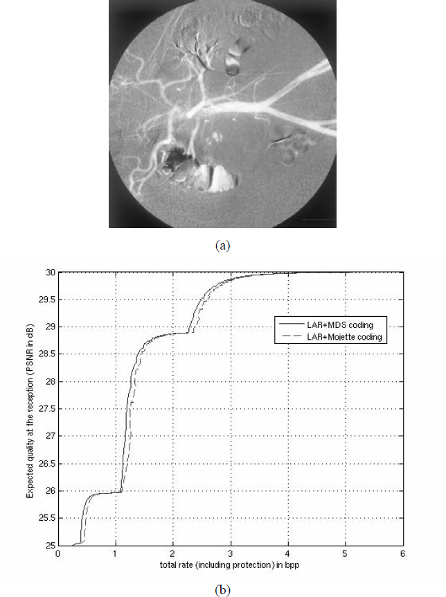
Figure 11.14. Mojette unequal protection applied to LAR source coding of a 512(512 angiographic image: (a) preview of the raw angiographic image; (b) rate/quality analysis for two joint source-channel: LAR source coding with RS and Mojette coding
11.5. Conclusion
The aim of this chapter was to highlight, on the one hand, the difficulties related to joint coding, dedicated specifically to the medical data in complex geographic environments and, on the other hand, to provide some useful prospects. The problem can be expressed simply: the more significant the compression rates become, the more sensitive the information provided by the encoder system is. Therefore, this makes it necessary not to separate the links constituting the source encoding and the channel encoding. In fact, some protection methods which use detecting/correcting codes can solve some situations, but require an increased redundancy. Moreover, their correcting capacity is limited because only one erroneous bit may involve the loss of the entire image.
Even if we know that the joint source-channel coding is the subject of very active research, it still remains far from being optimal. Therefore, unequal error protection codes are currently under development such as the Mojette transform which proposes an intelligent protection depending on the importance of the source information contained in the binary stream. These codes modify the organization of the source data when packet losses appear.
Likewise, joint decoders have been developed. We can cite, in particular, those built for convoluted codes and the turbo-codes [JEA 05], starting from a probabilistic estimation of the source model and a joint coding associating arithmetic coding (VLC) and correcting codes ECC.
In general, for multimedia information, this problem remains both open and promising. However, it is essential to solve it within the context of medical data reading. Of course, an appropriate quality of service should be guaranteed.
11.6. Bibliography
[ALB 96] A. Albanese, J. Blömer, J. Edmonds, M. Luby, and M. Sudan, Priority Encoding Transmission, IEEE Trans. on Information Theory, 42, p 1737-1744, November 1996.
[BAB 05] M. Babel, B. Parrein, O. Déforges, N. Normand, JP. Guédon, J. Ronsin, “Secured and progressive transmission of compressed images on the Internet: application to telemedicine”, SPIE Electronic Imaging 2005, vol. 5670, p. 126-136, San Jose (CA), January 2005.
[BER 93] C. Berrou, A. Glavieux, P. Thitimajshima, “Near Shannon limit error correcting coding and decoding: turbo-codes”, IEEE Int. Conf. on Communication, 2/3, p. 1064-1071, Geneva, Switzerland, 1993.
[BLA 98] S. Blake, D. Black, M. Carlson, E. Davies, Z. Wang, W. Weiss, An architecture for differentiated Services, IETF RFC 2475, available at http://tools.ietf.org/html/rfc2475.
[BRA 94] R. Braden, D. Clark, S. Shenker, Integrated services in the Internet architecture: an overview, IETF RFC 1633, available at http://tools.ietf.org/html/rfc1633.
[COM 06] P. Combeau, R. Vauzelle, L. Aveneau, “Efficient ray-tracing method for narrow and wide-band channel characterization in microcellular configurations”, IEE Microwave, Antennas and Propagation, 153 (6), p. 502-509, December 2006.
[DEB 00] V. DeBrunner, L. DeBrunner, L. Wang, S. Radhakrishan, “Error control and concealment for image transmission”, IEEE Commun. Soc. Survey Tutorial, 3 (1), p. 2-9, 2000.
[GOY 01] V. Goyal, “Multiple Description Coding: Compression Meets the Network”, IEEE Signal Processing Magazine, 18, p. 74-93, September 2001.
[GUE 05] J.P. Guédon, N. Normand, “The Mojette Transform: the first ten years”, DGCI 05, Springer, Proceedings of DGCI, p. 136-147, Poitiers, France, 2005.
[HAM 05] R. Hamzaoui, V. Stankovic, Zixiang Xiong, “Optimized error protection of scalable image bit streams [advances in joint source-channel coding for images]”, IEEE Signal Processing Magazine, 22 (6), p. 91-107, November 2005.
[ISK 02] M. F. Iskander and Z. Yun, “Propagation prediction models for wireless communication systems”, IEEE Trans. on Microwave Theory and Techniques, 50 (3), March 2002.
[JEA 05] M. Jeanne, J.C. Carlach, P. Siohan, “Joint source-channel decoding of variable length codes for convolutional codes and turbo codes”, IEEE Trans. On Communications, 53 (1), p. 10-15, January 2005.
[LEE 93] C.Y. Lee, Mobile Communications Design Fundamentals, Wiley Series in telecommunication, 1993.
[LIN 05] S. Lin, D.J. Costello, Error Control Coding: Fundamentals and Applications, 2nd ed., Prentice Hall: Englewood Cliffs, NJ, USA, 2005.
[MAC 04] D.J.C. MacKay, Information Theory, Inference and Learning Algorithms, Cambridge University Press, version 7.0, November 2004.
[MOH 00] A.E. Mohr, E.A. Riskin, R.E. Ladner, “Unequal loss protection: graceful degradation of image quality over packet erasure channels through forward error correction”, Journal on Sel. Areas in Communication, 18 (6), p. 819-828, 2000.
[PAR 92] D. Parsons, The Mobile Radio Propagation Channel, Wiley-Pentech Publication, 1992.
[PRO 00] J. G. Proakis, Digital Communications, 4th ed., McGraw-Hill, 2000.
[REE 60] I.S. Reed and G. Solomon, “Polynomial codes over certain finite fields”, Journal of the Society of Industrial and Applied Mathematics, 8 (2), p. 300-304, 1960.
[RIZ 97] L.M. Rizzo, “Effective erasure codes for reliable computer communication protocols”, ACM Computer Communication Review, 27, p. 24-36, April 1997.
[SOU 04] B. Souhard, Codage conjoint source canal: application á la transmission d'images fixes sur canal ionosphérique (in French), Thesis, Poitiers, France, 2004.
[TAU 03] D. Taubman, R. Prandolini, “Architecture, philosophy and performance of JPIP: internet protocol standard for JPEG2000”, International Symposium on Visual Communications and Image Processing (VCIP2003), SPIE, vol. 5150, p. 649-663, July 2003.
[VAU 04] R. Vauzelle, Y. Pousset, F. Escarieu, “A sensitivity study for an indoor channel simulation”, Annals of Telecom, 59 (5-6), p. 655-672, May 2004.