
Chapter 4
Standards in Medical Image Compression
4.1. Introduction
A standard (or norm) is a specification which has been adopted by those working within a particular field, in order to describe a process in an organized manner. In the case of data compression, the use of standards is particularly important as the compression process aims at the creation of an intermediary form of the information, which is more compact, and therefore easier to send over communication networks, to store and to receive. In other words the compressed form is not an end in itself; it is only an intermediary between a creation process and usage. It is therefore essential that this intermediary form or, if required, the means of access to this form conforms to specifications which ensure a smooth interaction between creation and usage.
A second motivating factor is the necessary life-span of the information. The existence of standards recognized by international bodies is a guarantee of the endurance of compressed data, and the continuation of the programs which create and read them.
Here, it is of interest to look specifically at medical data (see Chapter 3), compared to other computerized data. Does this field require the creation of specific standards, uniquely for the compression of medical data, in particular images? We can anticipate two different views on this matter.
Firstly, from a theoretical perspective, it seems desirable to keep the use of specific standards to a minimum, both for reasons of efficiency – to avoid repeating work which has already been carried out in part in other research circles – and also to minimize the cost of components. The latter argument is the more pertinent: the most general information treatment mechanisms lead to uses on a very large scale, in the form of specialized processors, with optimal performance, reliability and cost, which is impossible to achieve with products specific to one particular field.
Secondly, in practice, choices are clearly not made based on purely rational criteria, but rather emerge from a wider context. A determining factor concerns in particular the ability to identify common needs within a given context. Thus, for example, it is to be expected that the standards within medical image compression should be tackled by DICOM (Digital Imaging and COmmunications in Medicine), and that the solutions most widely-used today should have been defined within this particular context, bringing together the key industrial and academic professionals in the field, rather than in a wider circle such as the ISO (International Standards Organization). In this chapter it will become apparent, however, that adopting specific solutions by no means excludes the use of the most general standards and technology.
The implementation of standards is therefore essential in this field, in order to meet the needs for interoperability and life-span which arise from the healthcare sector. This brings with it certain side-effects. It can be frustrating for researchers working in data compression to know that if the advances they make are to be widely-used, not only will they have to offer a significant advantage over currently existing standards, but they will also have to be recognized by the standardization bodies, a process which can take several years. Nevertheless, this research is essential in order to achieve progress within the standards (JPEG 2000 became a standard only after considerable fundamental research into discrete wavelet transform).
In this chapter, we begin with a look at standardization and the bodies which set these norms in the field of medical data. Here, we will introduce the DICOM standard and will consider some key ideas in order to achieve a thorough appreciation of the implementation of image compression in this standard. The following section will detail the different types of compression available in the DICOM standard, as well as the methods of accessing compressed images. Finally, we will conclude by highlighting the key points within the use of image compression standards, particularly within the context of healthcare networks.
4.2. Standards for communicating medical data
4.2.1. Who creates the standards, and how?
We can generally distinguish three categories of standards.
The de jure standards are those created by official standardization bodies such as the International Standards Organization (ISO) or in Europe, the European Committee for Standardization (Comité Européen de Normalisation or CEN). The representation of the principal players is organized by country. This means that the selected experts represent the official standardization body of their country, for example, AFNOR (Association Frangaise de Normalisation) for France. The issues in question are therefore defined at this level by “mirror groups” of the international committees concerned. This approach has the advantage of guaranteeing free access to the creation of a standard by all interested parties, whether they are from industry, from academia, consumer associations, public bodies, etc. One of the two main criticisms of this approach is that it leads to a rather long standardization process – around 5 to 10 years – despite the fact that in fields such as IT and communications, technological advances happen at a very fast rate, meaning that a standard, once approved, can be out of pace with market needs, simply due to technological advances. Another criticism is that this approach does not give a sufficiently important role to the industrial players within the field. In fact, many norms are defined without ever being used in products. Some see this as the consequence of the unnecessary complexity of the solutions offered, imposed by academics or consultants, who are more concerned with the scientific quality of the solutions than the economic viability of products which use these norms. The European Community's procurement rules require that contracting bodies are obliged to define their specifications with reference to European standards, where available.
Industrial standards are created by associations of developers or academic bodies such as, for example, the World Wide Web Consortium (W3C), the Internet Engineering Task Force (IETF) – two bodies who play a key role in Internet standards – or the DICOM committee regarding the DICOM standard. These organizations set industrial standards, usually via very well-defined procedures, which are accepted by national standards bodies. These associations operate on a voluntary basis. In general, free access to standardization records is available online.
Unlike those produced in either of the two contexts given above, “de facto” standards do not arise from a formal agreement between interested parties, but rather from a process of market selection. Into this category fall Word and the Rich Text Format (RTF, Microsoft™), the Portable Document Format (PDF, Adobe™), which have become standards only as a result of endorsement from huge communities of users, which has led to their standardization.
4.2.2. Standards in the healthcare sector
4.2.2.1. Technical committee 251 of CEN
Within Europe, the technical committee 251 of CEN, “Health Informatics” (http://www.centc251.org) was founded in 1991 to develop a group of standards for the exchange of health data in conditions which guarantee interoperability, security and quality. This committee is organized into four working groups focusing on information models (WG I), terminology and knowledge representation (WG II), security and quality (WG III), and technologies of interoperability (WG IV). This committee has produced a significant number of technical reports, experimental norms (ENV), as well as some European Norms (EN). The most important is ENV 13606 “Electronic healthcare record communication”, itself divided into four parts: 1) architecture, 2) domain term list 3) distribution rules and 4) messages.
We can also cite norms or pre-norms on communication security (ENV 13608 – 1 to 3), the recording of coding systems (ENV 1068), messages for the exchange of information on medical prescriptions (ENV 13607), blood transfusion related messages (ENV 13730 – 1 and 2) and a system of concepts to support the continuity of care (ENV 13940).
4.2.2.2. Technical committee 215 of the ISO
Technical committee 215 of the ISO (website accessible from http://www.iso.org), also called “Health Informatics”, was created in 1998, with a very similar objective to Technical Committee 251 of CEN, but for the world stage. This committee is organized into eight working groups: data structure (WG 1), information exchange (WG 2), semantic content (WG 3), security (WG 4), health cards (WG 5), pharmacy and medical products (WG 6), devices (WG 7) and business requirements for electronic health records (WG 8). The key standardization documents produced since the creation of Technical Committee 215 of the ISO concern the communication between medical devices (ISO/IEEE series 11073), the interoperability of telemedicine systems and networks (ISO/TR 16056 1-2), public key infrastructure (ISO/TR 16056 1-2), web access for DICOM persistent objects (ISO 17432) and patient healthcare data (ISO 21549 1-3).
4.2.2.3. DICOM Committee
A recap of its history: the DICOM Committee (http://medical.nema.org) in its current organization has existed since the early 1990s. This Committee is the successor of the ACR-NEMA Committee, formed in 1983 by the American College of Radiology (ACR) and the National Electrical Manufacturers Association (NEMA), with aims of internationalization. Today it incorporates around 40 players from academia and industry, working in the field of biomedical imagery (Table 4.1).
Table 4.1. List of organizations present in the DICOM Committee
All the key players in medical imagery actively contribute to the development of the standard. Today there are 26 working groups, bringing together around 750 technical or medical experts. These groups are listed in Table 4.2.
Table 4.2. List of the DICOM Committee's working groups
The DICOM 3.0 standard was published in 1993, following preliminary work carried out over the previous decade, and which led to the ACR-NEMA standards 1.0 and 2.0 (published in 1985 and 1988 respectively).
Field covered: the DICOM standard [DIC 06] covers many areas, including:
– the communication of related images and data (over a network or using physical media), for almost every existing technique (image modality);
– the printing of images onto physical media;
– the communication of reports on imaging procedures;
– the management of activities related to the acquisition, treatment and interpretation of images, through the management of “work lists”;
– the security of data exchange, via a service called “storage commitment”, and various mechanisms for digital signature of documents;
– the coherence of image rendering on hardcopy and softcopy (monitor display).
The standard is modular, so as to effectively meet general or specific needs concerning the numerous modalities within imagery and medical specialities making use of imagery. It is organized into 18 relatively independent sections (Figure 4.1).

Figure 4.1. The different sections of the DICOM standard
Key principles of the DICOM standard: the following elements focus on the key notions which must be grasped in order to understand the implementation of compression in the DICOM standard. For a more detailed look at the standard, see [CHA 04].
DICOM is, above all, a protocol for image exchange, over a network or with the aid of physical media (CD ROM, DVD, etc.). Taking into account the diversity of image modalities, the standard is organized in such a manner as to allow both the specificities of each modality to be respected, and to create common ground between many data elements.
Thus, the standard is organized in a modular manner, particularly through the “Service Object Pair” (SOP) principle, linking a class of images of a certain kind, for example CT (Computed Tomography) images or X-ray tomography images, to a specific exchange service (for example the “image storage” service). This idea of “classes”, inspired by the “object” paradigm, leads us to discover the notion of an “SOP class” – an abstraction of all the images of a certain type, CT for example – and the notion of an “SOP Instance”, which refers to a concrete image example, identified thanks to a unique identifier. One essential function of this notion of SOP class concerns conformance to the standard. It is by referring to the different SOP classes that developers claim that their products conform, using a “DICOM conformance statement”, compiled following the prescriptions contained in Part 2 of the standard. For a given SOP class, we determine the Service Class Provider (SCP) and the Service Class User (SCU). For example, in the case of the SOP class “CT Image Storage”, the application entity playing the role of the SCU is the application which “pushes” the image, whereas the application that takes the role of the SCP is the one that receives the image.
The specification of the data elements to be transmitted corresponds in DICOM to the idea of Information Object Definition (IOD). An IOD specifies a list of data elements, giving: 1) the general context of image acquisition (essential information on the patient, the study, and the series), 2) the acquisition procedures (particularly the physical acquisition methods, the reconstruction algorithm, etc.), 3) the image's characteristics (size, resolution, etc.) and 4) the pixel data itself. The “module” concept, by gathering together data elements relating to the same information entity (for example “Patient Module” or “General Study Module”), makes it easier to reuse them in different IODs. These information entities are defined via information models, following the “entity-relationship” formalism. In this chapter, we need think no further than the idea of a simple hierarchy along the lines of: patient – study – series – composite object, represented in Figure 4.2.
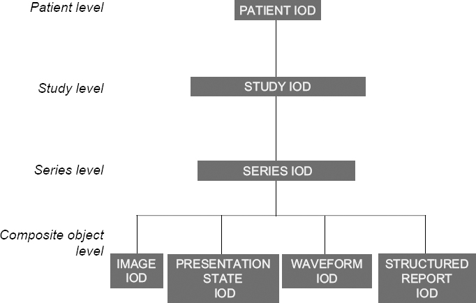
Figure 4.2. Hierarchical model of DICOM entities
This notion of composite objects, initially introduced to express the aggregation of information which concern different real-world entities, allows us to generalize, in management terms, all DICOM entities which have a persistent character. This concerns in particular images, but also “presentation states”, which allow us to choose a specific appearance for the images (for example, a particular window or zoom rate), structured reports, able to reference images and waveforms, used to represent physiological signals such as the ECG.
As for the image data itself, DICOM decided from the outset to give a classical definition of the image: as a simple 2D representation of values, each image in a series representing an individual dataset, and carried by an individual message. Thus a series of 100 CT images results in the sending of 100 separate messages. Meanwhile, the principle of a “multi-frame” image was conceived, particularly when representing ultrasound images. Today it is becoming more widespread, with the specifications of Enhanced MR and Enhanced CT objects, designed to cope with the growing needs of MRI and CT imagery.
4.2.2.4. Health Level Seven (HL7)
HL7 (http://www.hl7.org) was initially an American organization for standards definition, accredited by the American National Standards Institute (ANSI), and which is now internationally recognized, with national groups in many different countries. The name of this standard refers to the seventh application layer of the OSI (Open System Interconnection) model of the ISO. HL7 was created to develop standardized messages allowing health information system applications to communicate between one another. Table 4.3 summarizes the different versions which have been published. The current version is 2.5 (March 2005). HL7 uses Arden Syntax, a syntax devoted to the representation of medical information in professional systems. Version 1.0 was developed and published in 1999 by the American Society for Testing and Materials (ASTM), before being taken up by HL7. HL7 has also integrated the Clinical Context Object Working Group (CCOW), whose aim is to synchronize desktop applications with a given context (user, patient, etc.). Alongside HL7 v3, HL7 has developed a Clinical Document Architecture (CD A), which in its second version, CD A release 2, has been an ANSI standard since April 2004. This architecture was initially in competition with that proposed by the CEN (ENV 13606), but now the groundwork has been carried out alongside the CEN experts, to merge the two architectures. Aside from its collaboration with the CEN, HL7 works closely with the ISO/TC 215, a pilot project which has been approved with the aim of having certain HL7 standards approved by the ISO.

Table 4.3. The different versions of the HL7 standard1
4.2.2.5. Synergy between the standards bodies
Each standards body develops its standards in relation to its own objectives and rules. Thus, we note that the official organizations (ISO, CEN) have a top-down approach to problems, whereas industry associations generally have shorter-term approaches, with more pragmatic attitudes, guided by the market (a bottom-up approach) [GIB 98]. We also often observe a widening of the area covered by a body, going beyond its initial remit. Thus, the DICOM standard, which was very much focused on imagery when it first began, has come to take an interest in the structure of medical documents, such as structured reports, thereby coming across problems encountered by other organizations, in this case the CEN (ENV 13606 part 1), and particularly HL7, with the architecture of CDA documents. This leads, therefore, to collaboration between standards bodies, by various different means. For example, there was an active collaboration from 1994 to 1997 between DICOM and CEN TC 251, serving to define collaboratively DICOM extensions affecting imagery workflow (managing working lists, storage commitment, etc). In the end, the entirety of the DICOM standard was recognized by the CEN as a European norm (CEN EN 12052) [CEN 04]. Similarly, an active collaboration was begun shortly after between CEN TC 251 and HL7 for the creation of Version 3 of this standard, concerning in particular the Reference Information Model (RIM) to draw all possible lessons from the work on the pre-norms ENV 13606. There is also a joint working group between DICOM and HL7 (DICOM's WG 20), to harmonize data exchange concerning imaging procedures and reports (structured or not) between these two standards. Lastly, there is also a type A liaison between the ISO TC 215 and the DICOM Committee, which renders official the acknowledgement of the fact that biomedical imagery is specifically studied in the DICOM Committee, then formally adopted by the ISO via a fast-track process. Thus, part 18 of the DICOM standard on the access to DICOM persistent objects has been adopted by the ISO (ISO 17432-2004).
4.3. Existing standards for image compression
4.3.1. Image compression
The general standards in the field of data compression can be divided into two categories:
– those relying on a particular spatio-temporal organization (2D image, or series thereof);
– those which do not make such a hypothesis.
The first have been developed chiefly by the ISO, to meet the needs encountered in photography (still images), cinema and television (animated images): these are the JPEG and MPEG families of standards, from the names of the working groups created by the ISO to work on these issues, the Joint Photographic Experts Group and the Moving Picture Experts Group respectively. The applications targeted at the outset were mainly linked to e-commerce (online catalogues), the press and tourism. The expansion into professional imagery occurred naturally in the fields using visible light (satellite imagery, the controlling of industrial processes, CCTV, etc.).
Common ground between general standards and specific standards: emerged perfectly organically. Two main approaches can be distinguished, as shown in Figure 4.3. The first approach uses compression techniques making no hypothesis about the nature of the information to be coded; into this category fall the compression tools distributed with UNIX/Linux such as “compress” or “gzip”, or used by programs such as “WinZip™” (Figure 4.3, approach 1). The second approach focuses the compression task on the data of the signal image (in the widest sense), exploiting the redundancy present in the different spatial or temporal dimensions. The representation of this data can either be based on the general standards of data compression (as in Figure 4.3, approach 2a and 2b), or not (see Figure 4.3, approach 2c).
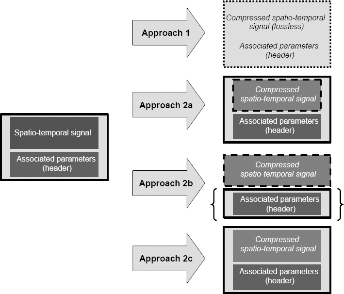
Figure 4.3. General and specific approaches to image compression; the left-hand part of the figure represents the image data and header; the right-hand part describes each of the four possible approaches, numbered 1, 2a, 2b, and 2c respectively. The borders of the boxes represent the type of standard containing the data, i.e. general standards (e.g. JPEG, MPEG), represented by a dotted border or specific coding (e.g. DICOM), represented by a continuous line
The advantages and disadvantages of the two approaches are summarized in Table 4.4. The first approach is used for lossless coding. It has the distinct advantage of being unspecific, i.e. it can be applied to any file, whatever its format or size. The disadvantage is that of limited effectiveness, dependent upon the data itself. Thus, noisy image data (without large uniform areas) is difficult to compress at a compression rate greater than 3:1. In contrast, the second approach can use image spatial and temporal structure in order to optimize the elimination of redundancy. The resulting compression rates – when lossy coding is acceptable – can be very significant, with factors ranging between 8:1 and 20:1, or even higher. The use of standard compression methods and formats makes the use of general decompression and visualization programs (e.g. web browsers) much easier.

Table 4.4. Advantages and disadvantages of general versus specific standards
4.3.2. Image compression in the DICOM standard
As we have seen, the DICOM standard plays a dominant role in the field of medical imagery. DICOM included very early on in its standard a possible recourse to data compression methods. The main aim of this section is to show how DICOM integrates the use of image compression, and particularly how DICOM has integrated the general approaches to compression provided by the ISO. For ease of comprehension, we will begin with a few reminders about the coding of data in the DICOM standard.
4.3.2.1. The coding of compressed images in DICOM
General aspects: the coding of data elements is described in part 5 of DICOM, called “coding”. It is carried out in binary, following a structure of the “type – length – value” type. The type field is expressed in the form of a pair of unsigned integers (represented on 16 bits) called a Tag. This is a simple unique ID (UID) for the element in question. For example, the Tag (0028,0010) Rows represents the number of lines in an image. The field length is represented in unsigned binary on two bytes – it denotes the number of bytes occupied by the value field. The value field contains the value of the data element in question.
The data elements are defined in part 3 of DICOM, at the semantic level, in tables corresponding to the different modules. Each line of these tables details:
– the Tag of each element;
– its name;
– its mandatory or optional nature: type 1: mandatory (i.e. present and not empty), type 2: present (but possibly empty), type 3: optional;
– the free text definition of the element.
This information is complemented in Part 6 of DICOM (the data dictionary), which defines for each data element:
– its Tag;
– its name;
– its value representation (VR); DICOM defines (at the start of Part 5, “coding”) 27 types of element, including: Unsigned Long (UL), Unsigned Short (US), Person Name (PN), etc.;
– its multiplicity value (the number of possible occurrences).
The data elements are then listed in increasing order to form a dataset, the body of the message. An example is given in Figure 4.4. There are different transfer syntaxes, taking into account different coding options, the main ones being:
– whether or not the data element type is explicitly given (Explicit Value Representation, for example);
– the order of the representation of the bytes: big-endian (the most significant byte is represented first, and then the others in decreasing order of significance), or little-endian (the less significant byte is represented first, and the others are listed in growing order of significance);
– the data compression usage, which we will look at in detail below.
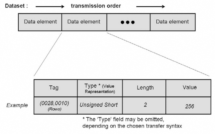
Figure 4.4. The organization of data elements, following the Tag – length – value triplet
The pixel data is represented in the data element (7FE0,0010) Pixel Data, which can be of the Other Word String (OW) or Other Byte String (OB) type. As a general rule, the data is packed taking into account the elements (0028,0100) Bits Allocated and (0028,0101) Bits Stored. We can in fact distinguish two different cases: the first concerns the native format (without compression), and the second is the format with encapsulation (with compression). In the first case, the pixel data is subject to compacting in which the last bit of a pixel stored is immediately followed by the first bit of the following pixel, following a constant order (the pixels follow on from left to right, and from top to bottom, meaning that the first pixel transmitted is that situated at the top left, followed by the rest of the first line, then the first pixel in the second line, and so on). Depending on whether the OW or OB type is used, the coding will or will not (respectively) be affected by the choice of a big-endian or little-endian ordering.
Encapsulation of compressed images: coding by encapsulation involves the inclusion in the data element (7FE0,0010) Pixel Data of the bit stream expressing the compressed image. In this case the transfer syntax used has to be of the explicit VR type, which means that the specification of the element type is present in the bit stream. Also in this case, the data element (7FE0,0010) Pixel Data is necessarily of the type OB, and the ordering has to be little-endian. Different compression techniques can be used, using the corresponding choice of transfer syntax.
As a general rule, the values given in the data elements specifying the coding of the pixel data (Photometric Interpretation, Samples per Pixel, Planar Configuration, Bits Allocated, Bits Stored, High Bit, Pixel Representation, Rows, Columns, etc.) must be consistent with those which appear in the bit stream of the compressed image. If there is inconsistency, it is advisable for the decoding process to use the parameters given in the bit stream representing the compressed data.
4.3.2.2. The types of compression available
JPEG image compression: the International Standards Organization ISO/IEC JTC1 has developed two international standards called respectively ISO/IS-10918-1 (JPEG Part 1) and ISO/IS-10918-2 (JPEG Part 2), and known as the JPEG standard of compression and coding of still images [ISO 95]. The standard specifies both lossy and lossless coding processes. This standard uses Discrete Cosine Transform (DCT), which allows an adjustment of the compression rate (see Chapter 2). The lossless coding process uses the Differential Pulse Code Modulation (DPCM). From the many modes available in the JPEG standard, the DICOM standard eventually retained four. Their principal characteristics are shown in Table 4.5.
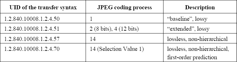
Table 4.5. Transfer syntaxes implementing the JPEG standard
The compression modes are referenced thanks to four different transfer syntaxes. The first corresponds to the baseline mode, applied to images on 8 bits, lossy and using Huffman coding. The second corresponds to the JPEG 2 and 4 modes, known as “extended”, also lossy, which are applied respectively to images on 8 and 12 bits. The third corresponds to the JPEG 14 mode, lossless, based on the DPCM method, still with Huffman coding. Lastly, the fourth differs from the third in that it involves an order 1 prediction (i.e. horizontal).
In order to facilitate the interoperability of applications using JPEG transfer syntaxes, the standard explicitly states that:
– applications using lossless JPEG must support JPEG mode 14 (the fourth given in Table 4.5);
– applications using lossy JPEG for images on 8 bits must support JPEG mode 1 (the first given in Table 4.5);
– applications using lossy JPEG for images on 12 bits must support JPEG 4 mode (the second given in Table 4.5).
Lastly, the developer must note in his or her DICOM conformance statement whether it is only capable of receiving compressed images, or whether it can also treat them.
Run Length Encoding (RLE) compression is a very simple coding algorithm based on the removal of repetitive patterns, used in the TIFF 6.0 format, called PackBits [TIF 92]. Note that in this case the data element (0028,006) Planar Configuration takes the value color-by-plane, in order to maximize the size of the uniform patterns. The corresponding transfer syntax carries the UID 1.2.840.10008.1.2.5. It can be used for both single images and multi-frame images. In the latter case, each frame leads to a separate fragment in the bit stream.
JPEG-LS image compression: JPEG-LS, i.e. ISO/IS-14495-1 (JPEG-LS Part 1) presents another standard proposed by the International Standards Organization ISO/IEC JTC1 to represent compressed still images, whether lossy or lossless [ISO 99]. It specifies a unique compression mode, founded upon a predictive method using a statistic model, modeling the differences between pixels and their neighborhood. This method is considered to be more effective than that given in JPEG, i.e. ISO 10918-1. It should also be noted that JPEG-LS can treat images up to a depth of 16 bits. Two DICOM transfer syntaxes have been defined: the first, which has the ID 1.2.840.10008.1.2.4.80 references the usage of JPEG-LS in lossless mode. The second, with the ID 1.2.840.10008.1.2.4.81, references lossy JPEG-LS usage, with absolute error limited to a precise value, specified in the bit stream.
JPEG 2000 image compression: JPEG 2000 is the most commonly-used name for the standard ISO/IEC 15444 (JPEG 2000), still dedicated to the representation of compressed still images [ISO 04a] [ISO 04b]. It introduces new compression schemes based upon Discrete Wavelet Transform and multi-component transforms, notably applicable to color images. Part 2 of the standard (ISO/IEC 15444-2) complements Part 1 (ISO/IEC 15444-1) by extending the multi-component transforms ICT (Irreversible Color Transform) and RCT (Reversible Color Transform). These extensions represent in part DPCM-type prediction schemes, and also more complex transforms such as the Karhunen-Loève Transform. All these schemes are adapted to black and white or color image compression, up to a depth of 16 bits; signed or unsigned, lossy or lossless.
DICOM references this standard thanks to four transfer syntaxes, the first two based on ISO/IEC 15444-1, and the other two based on ISO/IEC 15444-2:
– the first, which carries the ID 1.2.840.10008.1.2.4.90 references the usage of JPEG 2000 Part 1 in lossless mode. It uses a compression scheme using Discrete Wavelet Transform or a multi-component transform in reversible mode, without quantification;
– the second, which bears the ID 1.2.840.10008.1.2.4.91 references the usage of JPEG 2000 Part 1 in lossy mode. This can use either reversible or irreversible transforms, with or without quantification.
– the third and fourth, which respectively bear the IDs 1.2.84.10008.1.2.4.92 and 1.2.840.10008.1.2.4.93, extend the possibilities of the first two transfer syntaxes, making use of the possibilities offered by JPEG 2000 Part 2. There is a generalization of the multi-component coding, which is applied in Part 1 of JPEG 2000 to color images, considering that any image sequence can be seen as a multicomponent image. A flexible mechanism allows for the organization and grouping of the components into component groups, for optimum efficiency. Applied to multi-frame DICOM images, these syntaxes therefore allow for the elimination of inter-image redundancy, independently from the semantic associated with this third dimension (space variable for 3D sequences, time variable for temporal sequences, etc.). These should therefore be used more and more extensively, with the diffusion of the new Enhanced CT and Enhanced MR IODs, which make extensive use of multi-frame images.
JPIP progressive image compression: this possibility was created in response to the need to send images progressively, i.e. allowing data display with growing precision as the transfer progresses. It therefore allows the user to see the image before the transfer is complete, or even to stop the transfer, if it is no longer what the user requires. The implementation of this mechanism is based on the Interactive Protocol proposed with JPEG 2000 (JPEG Interactive Protocol, or JPIP).
It is used in DICOM to replace the bit stream usually present in the data element (7FE0,0010) Pixel Data with reference to a data provider for this bit stream, given in data element (0028,7FE0) Pixel Data Provider URL, for example:
![]()
The JPIP server must return a dataset of Content-type image/jp2, image/jpp-stream or image/jpt-stream. It is also possible to specify a particular bit stream subset thanks to the modular nature of the coding, for example, the following URL allows for frame number 17 of a multi-frame image sequence to be restored at a resolution of 200×200:
![]()
These possibilities use two particular transfer syntaxes, JPIP referenced transfer syntax, with the ID 1.2.840.10008.1.2.4.94, and JPIP referenced deflate transfer syntax, with the ID 1.2.840.10008.1.2.4.95. The difference between the two lies in the fact that the second also adds a lossless coding of the JPIP bit stream, based on the deflate algorithm (RFC 1951).
MPEG2 image compression: the MPEG2 standard (ISO/IEC 13818-2) was developed by the ISO for the compression of video or animated images, and any associated sound signal [ISO 00] (see Chapter 2). Reference to this standard uses a unique transfer syntax, with the ID 1.2.840.10008.1.2.4.100. It references MPEG2's MPEG option MP@ML (MainProfile@MainLevel). MPEG2 MP@ML uses a source code in 4:2:0 reducing the input data rate to 162 Mbits/sec. The Main Profile (MP) indicates an MPEG sequence composed of images which may be intra (I), predictive (P) or bidirectional (B) and the Main Level (ML) at a definition equivalent to television standards. The output rate is not set by the standard -between 1.5 and 15 Mbits/sec.
This can be applied to single- or multi-component data represented on 8 bits (which can present a problem for the compression of medical images, often represented on more than 8 bits); in the case of single-component data, the data element (0028,0004) Photometric Interpretation has to take the value MONOCHROME2, whereas for multi-component data, it has to take the value YBR_PARTIAL_420. In both cases, the MPEG bit chain includes both a luminance signal and two chrominance signals. The spatial and temporal resolution of the images, i.e. the data elements (0028,0010) .Rows, (0028,0011) Columns, (0018,0040) Cine Rate and (0018,1063) Frame Time must be in conformity with the values specified for MP@ML, shown in Table 4.6.
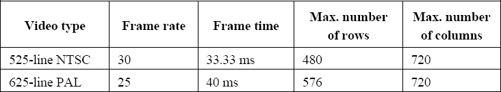
Table 4.6. Spatial and temporal resolution of images in the MPEG2 standard MP@ML; in practice, it is advised to follow a 4:3 ratio
4.3.2.3. Modes of access to compressed data
There are four exchange modes offered in the DICOM standard: 1) network exchange, using the STORAGE and QUERY & RETRIEVE services; 2) exchange using physical supports, for example CDROM or DVD; 3) email attachments; and 4) WADO (Web access to DICOM persistent objects). They were successively introduced into the standard to meet the needs of different applications. This section gives a brief introduction to the specificities of each of the exchange modes, and gives the part of the standard which details them.
Network exchange: this exchange mode (with the STORAGE and QUERY & RETRIEVE services) was already present in the 1985 and 1988 versions of the ACR-NEMA standard, and was taken up again in the DICOM 3.0 standard of 1993. It involves “pushing” the images one by one, by means of a C-STORE type message (defined in Part 7 of DICOM). These simple transfer operations can be integrated into wider transactions including search capabilities via criteria such as patient name or study number (QUERY & RETRIEVE): this uses other services defined in Part 7 of DICOM, i.e. the services C-FIND, C-GET and C-MOVE.
The use of exchanges over a network between two application entities requires the prior negotiation of services (SOP Class) and the transfer syntaxes to be used. This is called association negotiation. This negotiation is initiated by the requestor of the association, which gives the list of SOP Classes which it supports, specifying the role of each (SCU or SCP) as well as the potential transfer syntaxes. This SOP triplet Class – Role – Transfer Syntax is called the presentation context. The second application entity replies, giving in turn the supported presentation contexts, so that this negotiation can serve to define the list of services and syntaxes which can be used in the exchange.
It is at this stage therefore that the use of transfer syntaxes involving image compression techniques can be introduced. Next we must determine the ways of identifying the images, according to their original or compressed nature, as well as the rules which govern the conversions between an original, uncompressed format and a compressed format.
A general principle (below we will look at how it can be modified) is that the image exists independently of its encoding. Thus if an image is transferred from an image source to an image server using a transfer syntax A, this same image can be restored – via QUERY & RETRIEVE for example – by a work station using a transfer syntax B. All it takes is for transfer syntax B to have been given preference over syntax A during the association negotiation between the work station and the image server. We should remember that the choice of transfer syntax is determined by the order of presentation contexts proposed and accepted by those involved in the exchange, and it is not a specific choice made during a C-GET or a C-MOVE.
However, we do have to add some caveats. In the case of images compressed with a lossy method, it is possible that several copies of one image could be managed by an image server application in order to differentiate between the uncompressed images and the images compressed using various different compression techniques and therefore represented in different transfer syntaxes. There is therefore a data element (0028,2110) Lossy Image Compression, which when positioned at the value 01 indicates that the image has been subjected – at some point in its life – to a lossy compression. In this case the value 1 (i.e. the first field) of the data element (0008,0008) Image Type has to contain a DERIVED value, to indicate that it is a derived image. The application which creates such a derived image has to create a new instance of the image, called “derived”, giving it a new unique SOP Instance UID. A mechanism exists so that, following a QUERY & RETRIEVE query about an original image (not compressed), the service provider can indicate, via element (0008,3001) Alternate Representation Sequence, the existence of another (compressed) version of the image, in case the original image has not been saved.
Exchange via physical media: the communication of images via physical media was introduced into the DICOM standard in 1995, with the publication of supplements 1, 2 and 3 (Parts 10, 11, and 12 of the standard). Naturally, in this case no negotiation of the transfer syntaxes is possible. Thus, the copy of the image present on the physical medium explicitly states the transfer syntax used during the encoding. The choice of potential transfer syntaxes is determined by the “application profiles”, particular to a clinical field and the technology of a given physical medium. These are defined in Part 11 of the standard, Media Storage Application Profiles. Thus, for example, the profiles STD-XA1K-CD and STD-XA1K-DVD give the SOP Classes and the transfer syntaxes to use for exchange by CD and DVD respectively for angiographic images up to resolutions of 1024×1024 on 12 bits.
Email attachments: The ability to send images in the DICOM format as email attachments was introduced into the standard in 2001 with the publication of supplement 54. This extension defines a new application profile STD-GEN-MIME allowing the use of all DICOM composite objects and all existing transfer syntaxes. A group of DICOM files is contained in a new MIME (Multipurpose Internet Mail Extensions) entity called the DICOM file set, of the Multipart/mixed or Multipart/related type. Each file is coded in the form of a MIME component called DICOM File, of the Application/dicom type. It is advisable to use the extension “.dcm”. These specifications are dealt with in the RFC 3240 [RFC 02].
WADO access: Web access to DICOM persistent objects meets the increasingly present need to retrieve – via the Internet protocols http and https – DICOM persistent objects, whatever they may be (images, structured reports, etc.). It also tackles the need to reference these information objects very easily in the form of URL/URI (Uniform Resource Locator/Identifier) in all sorts of text or hypertext documents. This tool was introduced into the DICOM standard in 2003 with supplement 85, in the form of part 18 of the standard. It was also recognized by the ISO TC 215 (ISO 17432) [ISO 04c].
The DICOM persistent objects concerned can be divided into four categories: (1) images, (2) multi-frame images, (3) text objects and (4) other objects. Table 4.7 gives an exhaustive list of the MIME types that can be used in each of these four cases.
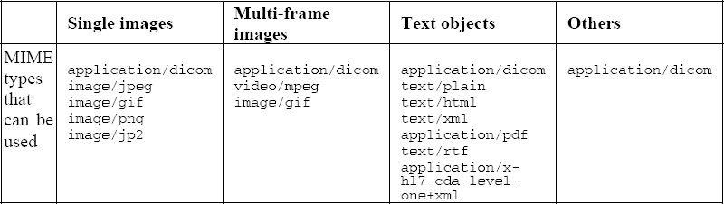
Table 4.7. MIME types that can be used in response messages with DICOM WADO
As we can see in this table, it is not only a question of allowing the use of access methods other than the traditional DICOM exchange protocols (QUERY & RETRIEVE), but also of making data retrieval easier in general syntaxes such as JPEG, GIF or MPEG, without encapsulation into the traditional DICOM syntaxes.
The format of the requests is based on the standard format of URL/URI specified in the RFC 2396. The main parameters are as follows:
– requestType (obligatory value: WADO);
– studyUID, series UID, objectUID, corresponding to the three levels of DICOM's “study – series – composite object” hierarchy;
– contentType, containing the list of MIME types which can be used.
Other optional parameters can also be defined, including:
– charset, to determine the set of characters to use, in order of preference (this is just as relevant to text objects as DICOM objects represented with the MIME type Application/dicom);
– anonymize, to state that the object must be anonymized;
– annotation, to state that annotations (concerning the patient and the technique) must be burnt into the pixel data (only relevant for images, and with a MIME type other than Application/dicom);
– rows, columns, region, windowCenter, windowWidth, frameNumber, to specify the image or section of image to return.
4.4. Conclusion
Bearing in mind the large volumes of data which result from medical imagery, the use of compression techniques – lossy or lossless – is clearly desirable. The need to share these images – within a hospital, but especially over a healthcare network -creates a strong need for standards, to guarantee the interoperability of applications and give long life spans to the data in question. Lastly, the context of national-level usage of the Personal Medical File will lead to the fundamental question of the role of medical imagery within these files. It is evident today that having standards adapted to the representation of compressed images is essential for the images to be correctly represented in these files. Faced with these needs, numerous possibilities exist, offering performance levels which can be qualified as satisfactory today, in both lossy and lossless compression [CLU 00].
Nevertheless, the ever-increasing volume of image data in existence represents a challenge for the future. This increase is in part due to new multi-slice CT scanners, but also to the development of dynamic imagery (X-ray imagery, ultrasound, dynamic MRI, endoscopy) and to the progress of digitization in anatomopathology (virtual slices). This evolution always calls for an improved performance within the fields of image compression and the communication of compressed data. Therefore, the ball is in the court of technical experts working in the field of image compression, who will undoubtedly rise to the challenge. The experience of the past 10 years has shown that the algorithmic progress achieved in lab results in international standards, both via the ISO and other standards committees such as DICOM. This requires time and effort, but it is essential if a standard is to be recognized and benefit from wide-spread usage in the industry.
4.5. Bibliography
[CEN 04] CEN EN 12052 – Health Informatics – Digital Imaging – Communication, workflow and data management, 2004.
[CHA 04] CHABRIAIS J., GIBAUD B., “DICOM: le standard pour l”imagerie médicale”, EMC-Radiologie, vol. 1, p. 577-603, 2004.
[CLU 00] CLUNIE D.A., “Lossless compression of grayscale medical images – Effectiveness of traditional and state of the art approaches”, Proceedings of SPIE: Medical Imaging 2000, vol. 3980, p. 74-84, 2000.
[DIC 06] Digital Imaging and Communications in Medicine (DICOM) – National Electrical Manufacturers Association, Parts 1 to 18, 2006.
[GIB 98] GIBAUD B., GARFAGNI H., AUBRY F., TODD POKROPEK A., CHAMEROY V., BIZAIS Y., DI PAOLA R., “Standardisation in the field of medical image management: the contribution of the MIMOSA model”, IEEE Transactions on Medical Imaging, vol. 17, no. 1, p. 62-73, 1998.
[ISO 94] ISO/IEC 10918-1:1994 – Technologies de l'information – Compression numérique et codage des images fixes de nature photographique : principes et lignes directrices, JTC 1/SC29, 185 pages, 1994.
[ISO 95] ISO/IEC 10918-2:1995 – Technologies de l'information – Compression et codage numériques des images fixes à modelé continu : tests de conformité, JTC 1/SC29, 62 pages, 1995.
[ISO 99] ISO/IEC 14495-1:1999 – Technologies de l'information – Compression sans perte et quasi sans perte d”images fixes à modelé continu : principes, JTC 1/SC29, 66 pages, 1999.
[ISO 00] ISO/IEC 13818-2:2000 – Technologies de l'information – Codage générique des images animées et du son associé : données vidéo, JTC 1/SC29, 230 pages, 2000.
[ISO 04a] ISO/IEC 15444-1:2004 – Technologies de l'information – Système de codage d”image JPEG 2000 : système de codage noyau, JTC 1/SC29, 200 pages, 2004.
[ISO 04b] ISO/IEC 15444-2:2004 – Technologies de l'information – Système de codage d”image JPEG 2000 : extensions, JTC 1/SC29, 337 pages, 2004.
[ISO 04c] ISO 17432:2004 – Informatique de santé – Messages et communication – Accès au web pour les objets persistants DICOM, TC 215, 18 pages, 2004.
[RFC 02] RFC 3240 – Digital Imaging and Communications in Medicine (DICOM) – Application/dicom MIME Sub-type Registration, Internet Engineering Task Force (IETF), 2002.
[TIF 92] Adobe Developers Association, TIFF Version 6.0, 1992.
1 The differences between the sub-versions arise from the longevity of the standard and its permanent ability to meet needs (addition of missing messages or fields, or deletion of obsolete ones).