Chapter 3
Clustering Design
In this chapter we will provide you with all the functional and technical details you need to design your clustering solution. We will cover topics such as how many nodes to choose and how to configure eDirectory on your cluster. We will also give you some practical tips on how to set up clustering for applications that do not require shared storage.
In this section we will give you some general guidelines that will help you to design your clustering solution. You should really consider them as rules of thumb and not as the Law of Clustering. There are many parameters that can be different for your environment and that can make you decide to do it a little different.
Starting with NetWare 6, you can build a cluster with two nodes without the need to buy additional licenses. This is still so for Open Enterprise Server. It is therefore very tempting to implement just a two-node cluster. There is nothing wrong with building a two-node cluster per se, unless you do it for the wrong reasons. We have seen too many customers that implemented a two-node cluster to replace two existing servers and in that way tried to provide high availability.
Not only may it cause problems with the workload for a single-cluster node that will remain active in case of a failure, but also you will not have redundancy when you have to remove one node from the cluster; for example, to perform an upgrade. This is exactly the reason that Novell requires you to have at least three copies of an eDirectory partition to provide high availability for eDirectory itself (one master replica and two read/write replicas). If you had only two, whenever you had to bring a server down for maintenance or when a server failed, you would have no fault tolerance with only one single remaining replica. The same rule applies to building a cluster.
When looking at the number of cluster nodes you will need, it is important first to decide what services you want to run on these servers and what the server requirements are for these applications. Armed with that information, you can decide on the number of cluster nodes you will need. In most scenarios for up to six servers being replaced, it is a good idea to add one extra server to that needed number of cluster nodes. That way you can be certain that when a server fails, there are enough resources available on the remaining nodes that all resources run without any loss of performance. For this to work efficiently, create a failover matrix to define to what cluster node the resources will fail over in case of failure. How to create a failover matrix is explained later in this chapter.
For larger clusters from 6 up to 32 nodes, it will probably not be the case that you are replacing existing servers with a cluster solution. But even when this is the case, there will most likely be enough resources available in the cluster to run the services from a failed node, if you have created an efficient failover matrix.
When designing a cluster solution, you should also keep in mind that you can install two or more clusters in your environment. It might not be practical to build a large cluster of 16 nodes to run all your services. Even if your hardware and storage area network (SAN) scale up to this number of nodes, you should keep in mind that if you would ever need to do maintenance on the entire cluster, it affects your entire environment. Also, you cannot delegate part of the cluster administration to different administrators. This can especially be important in larger environments with a large number of servers, where, for example, a group of administrators can be in charge of application servers and another group handles file and print servers. To not have them interfere with each other, it could be better to have more than one cluster.
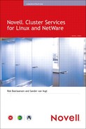
Novell Cluster Services (NCS) uses a heartbeat mechanism to detect whether all servers are available via the network. Besides this LAN heartbeat, there is also the Split Brain Detector (SBD) partition through which the status of servers is watched. It is possible to set up a dedicated LAN for the heartbeat channel. The benefit of this is that when the performance of the LAN drops, the heartbeat channel remains active without interruption. But this advantage is also a disadvantage: When the servers cannot contact each other for the heartbeat, the clients might also not be able to contact the servers. Especially when a network adapter on the client LAN fails and the heartbeat network remains active, the clients will lose their connection to the service that was handled by that network adapter, but the cluster node will stay alive. Figure 3.1 shows an example in which a network connection on the client LAN fails but the heartbeat remains active. The GroupWise post office running on the failing node is not moved to another node; thus, the clients will try to access it on the same host and will fail.
We advise against using a dedicated heartbeat LAN. It will prevent the previously described scenario, in which clients lose access to services, from happening. To be protected against communication failures due to a malfunctioning network adapter, it is better anyhow to set up network interface card (NIC) teaming. NIC teaming is described in the following text.
In Chapter 1, “Introduction to Clustering and High Availability,” we commented that looking into your high-availability solution should not only be looking at Novell Cluster Services. You should look into high availability for more than your servers. Examples are network switches and your data center power supply. Something else that can help you improve the overall availability for your environment is to use NIC teaming. This technology can help you remove the single point of failure for your network connections. If a network board fails and another one remains available, it would no longer mean that the cluster heartbeat is interrupted and a failover has to be performed.
Two types of NIC teaming are available. The first type is implemented in the hardware such that the operating system is not aware of the redundant NIC and a special driver must be used to send an alert that an adapter has failed. The other type is one in which the operating system takes care of bundling the network adapters, called bonding, into one logical device with a vendor-specific driver. We will describe how to set up NIC teaming in Chapter 9, “Advanced Clustering Topics, Maintenance, and Troubleshooting.”
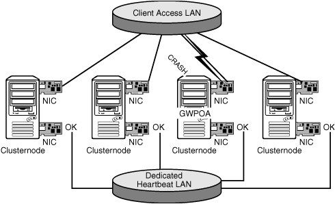
In the most basic form of NIC teaming, shown in Figure 3.2, a server has two network adapters that are connected to the network. The switch will still be the single point of failure in this example. To also create a redundant configuration for this part of the network configuration, two switches can be used to link the network adapters to different switches. For that to work, the drivers must support the IEEE 802.3ad Link Aggregation Control Protocol (LACP), which most network card vendors such as Intel and HP support.
In this section we will introduce the storage methods available for clustering. This is divided in three parts: the storage connection, the disk configuration, and the file system.
First of all, your cluster nodes need to have access to a shared storage medium. The choices you have are widespread, but we will discuss the three most common ones: SCSI (Small Computer System Interface), Fibre Channel, and iSCSI. The first technology is really a direct connection method, and the two others will form a storage area network.
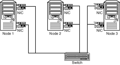
For a long time SCSI was the most used technology for attaching storage and other equipment to computers. With SCSI, disks and tape devices are attached to a SCSI bus that transports data blocks from one device to another. Figure 3.3 shows an example of a cluster with shared SCSI storage.
These types of clusters are simple in their nature. The two servers both contain a SCSI adapter that is set to a different SCSI ID, 6 and 7 in this example. The SCSI disk takes part of the SCSI bus too and is set to SCSI ID 0. Other devices that would be on the same SCSI bus would also be configured with a unique device ID.
Many hardware vendors sell servers in a clustered configuration with the servers and storage built into one rack enclosure or server casing. We use the phrase “cluster in a box” for such equipment.
SCSI is a technology that can be used for a two-node cluster. With the special hardware configurations for a shared SCSI cluster described before that are not too expensive, it is a good choice if you want to implement high availability in a small organization or at the departmental level. A two-node cluster should be deployed to replace the load of one single server and give the services from that server a higher availability.
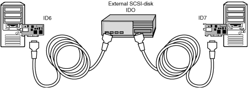
A storage area network is really what the name says: a network of computers and storage devices that access storage in a special-purpose network. Such a network can be built with a handful of technologies, but we will look at the two most commonly used ones: Fibre Channel and iSCSI. The latter is discussed in great detail in Chapter 7, “iSCSI,” so we will not go into too much detail for iSCSI here, and we will focus on what a SAN is and how Fibre Channel can be used to set it up. Figure 3.4 shows a basic example of what is needed to build a SAN with Fibre Channel equipment.

Every server needs to be equipped with a Fibre Channel Host Bus Adapter (HBA). From the server adapters a fiber-optic cable runs to a Fibre Channel switch. And last but not least, a disk system is attached to the same Fibre Channel switch.
The way that the disks can be used from the operating systems running on the servers is that the SAN provides LUNs (Logical Units) to the servers. Each LUN can be used as if it were one local disk in a server. Management applications such as iManager and NSSMU will display a LUN as a device, just as they would do for a local physical disk.
If you look at Figure 3.4 with high availability in mind, you’ll notice that the servers are redundant in that picture, but the SAN has several single points of failure. Therefore it is possible to add some redundancy into the SAN. Each server can be equipped with two HBAs, each connected to a separate switch. And the storage can be connected with two cables into these separate switches. In such a more redundant scenario, a switch or an HBA can fail without interrupting the service of the SAN. When you have such a setup in place, it is important that some sort of management algorithm be included in the SAN to take care of the multiple paths that become available. This is known as multipath support. Multipath is implemented in Novell Storage Services (NSS) but is also included in the drivers from many HBA manufacturers, such as QLogic, Hewlett-Packard, Emulex, and LSI Logic.
Fibre Channel technology can be used to create the largest clusters possible. It provides the fastest data throughput of all technologies discussed here. We are not sure whether we should call it a disadvantage, but for setting up a Fibre Channel SAN special technical skills are needed. Many customers let their hardware resellers set up the SAN for them to the point where LUNs are available to use from the clustering software. You may compare the technical expertise level needed to configure a SAN with that of configuring a switched ethernet network with Virtual LANs (VLANs) and spanning tree.
After you have set up a physical connection from every server to a storage device, it is important to look at how the disks are being used inside that device. This can range from a single disk to using hardware RAID (redundant array of independent disks) or software mirroring configurations.
These types of configurations are valid only for really unimportant data that can be missed for a day or two. You could be thinking of an archive that you want to keep online. In the old days there were technologies to keep data available on tape or optical devices with an easy mechanism to collect the data when needed. This was called near-line storage. With the availability of inexpensive large IDE disks, it has become possible to store such data online for a fraction of the cost that is required for either a tape library or expensive SCSI disks. In your clustered environment you can use a disk enclosure with 500MB IDE disks or an iSCSI target server with those disks to store data that is available through the cluster. But even then we advise you to use one of the technologies described hereafter to create redundancy for your disks. Especially with these not-too-expensive IDE disks, the time to restore data can be brought to zero for only a few hundred dollars.
The most widely used technology for disk redundancy and fault tolerance is RAID. Many levels of this technology are available, the most common being RAID 1 and RAID 5. But RAID 0+1 or RAID 10 is sometimes used. We will first explain some terminology here about RAID that we will use in the remainder of this section. An array is a set of combined disks. Two or more disks are grouped together to provide performance improvement or fault tolerance, and such a group is called an array. As for the operating system that works with that array, we call that a logical disk.
Note
First of all, a warning here about RAID 0: With that technology there really is no redundancy. There is performance improvement because the data is striped across multiple disks. But if one disk in a RAID 0 array fails, the entire array becomes unavailable.
RAID 1 mirrors disk blocks from one disk to a another disk. This means that every disk block being written to disk is also written to the second disk. The operating system connecting to the array sees one logical disk. It is the hardware RAID controller that takes care of the mirroring. In this scenario one disk could fail and the logical disk is still available to the operating system. RAID 1 improves the performance for read operations because data can be read from either disk in the mirror. This type of redundancy is the most expensive in terms of disk usage because it requires a double amount of disk capacity that is effectively needed.
RAID 0+1 and RAID 10 are both combinations of RAID 0 and RAID 1. With RAID 0+1 the RAID controller combines physical disks into a stripe set as a virtual logical disk. It does that for a minimum of two physical disks and also for two other physical disks. It then uses those two virtual logical disks, that are both striped, internally and mirrors them into one logical disk for the operating system. In a RAID 10 configuration it works the other way around: A minimum of two physical disks are first mirrored into a virtual logical disk, and the same happens for two other physical disks, after which the RAID controller stripes data over the virtual disks that are created. The effect of using these technologies is that they improve performance compared to regular RAID 1 mirroring. RAID 10 is your better choice over RAID 0+1 because it uses mirroring as the first defense against disk failures, whereas RAID 0+1 first stripes the disks and then uses mirroring only internally for the combined virtual disks.
In a RAID 5 configuration, data is striped across multiple disks and redundancy information is stored on the disks in the array. The way this works is that when blocks are written to the physical disks, a parity block is calculated for a combination of blocks of physical devices and written to one of the disks in the array. There is no single disk that holds all the parity information; it is striped across the disks in the array. In this configuration one of the disks in the array can fail and still all data is available because it can be reconstructed with the parity information from the remaining disks. Only when more than one disk fails does the entire array become unavailable. The great advantage of RAID 5 is that the extra disk capacity that is needed is kept to a minimum. For a combination of four disks, only one extra disk is needed. Buying five 72GB disks will provide you with a net 288GB disk capacity. The main disadvantage of RAID 5 is that it has a lower performance compared to RAID 1 because of the additional overhead of the striping process, whereas RAID 1 just writes the data to two disks without having to think about that.
An important feature of RAID configurations is that they support hot spare disks and sometimes also hot pluggable disks. With the first feature you can have a disk on standby that can be used to replace a disk immediately in case of a failure. If it supports hot-pluggable disks, you can add disks to the server while it is up. Depending on the RAID controller, you can even expand the array online and add the new segments to the operating system online. These two features are important to look out for when evaluating RAID controllers for your environment.
Besides redundancy that comes as hardware in your servers, it is also possible to use the operating system to create redundancy for your disks. This can be striping to improve performance (RAID 0), mirroring of disks or partitions (RAID 1), or even software striping for fault tolerance (RAID 5). The only solution we think could be used in any professional setup is software mirroring. Novell Storage Services supports this at the partition level. It can be used with physical disks but it is also a possible solution to mirror disks that are used with iSCSI.
On Linux there is also the possibility to use software RAID. Independent disk devices can be combined into a single device, for example, called /dev/md0, to provide fault tolerance. Check the manual pages for the commands raidtab, raidstart, and mkraid to see how to set up a software RAID configuration, or check the documentation on RAID at the Linux Documentation Project at the following URL: www.tldp.org/HOWTO/Software-RAID-HOWTO.html.
Another solution to create redundancy for disks in Linux is the Distributed Replicated Block Device (DRBD). This is a RAID 1 solution running over the network. In this configuration one node has read-write access to the DRBD device and the other node does not. This technology is described in detail in Chapter 11, “Using SUSE Linux Enterprise Server Clustering Options,” where it is used for Heartbeat, a high-availability solution for Linux.
If you can afford it, always use hardware redundancy with RAID 1 or RAID 5. You will get better performance because the RAID controller contains its own processor and cache memory to do its job. Also the management and alerting for hardware RAID are better than what you would get in any operating system.
With the storage connections in place and the disks configured for high availability, it is time to look at the last part of the storage component of a cluster solution: the file system.
Not all file systems are cluster aware and thus not all can be used with Novell Cluster Services. For NetWare there is nothing more to choose from than NSS, but not so for Linux.
When we first look at NetWare, we can use NSS as a file system in a cluster because it contains a feature called Multiple Server Access Prevention (MSAP). A node that activates a pool on the shared disk writes a flag to that disk to indicate that the pool is in use by that server. Other servers that have access to the shared disk will see that flag set and will not activate the pool. This prevents corruption that could occur when two servers were writing data to the same data area at the same time.
For Linux, NCS also works with NSS, but it can also support other file systems. Ext3 and ReiserFS are not cluster aware by nature; but they can be mounted on a server and whenever a failure occurs they can be mounted on another node in the cluster.
There are also true Linux cluster-aware file systems available. Novell Cluster Services supports the Oracle Cluster File System version 2 (OCFSv2), but other file systems that can be used for building a Linux cluster are RedHat’s Global File System and Polyserve’s symmetric cluster file system.
For the Open Enterprise Server environment your best choice is to use NSS, or alternatively when you want to cluster-enable Linux applications with OES, you could use Ext3 or ReiserFS.
In Chapter 8, “Cluster-Enabled Applications,” we explain what file systems to use for different types of applications that you can run in your Open Enterprise Server Linux environment.
For a cluster with shared storage, a small part of the shared disk, or maybe a special LUN on the SAN that you assign for this purpose, will be used as the Split Brain Detector partition. All cluster nodes write data to this disk to report about their status. If a cluster node does not respond to network heartbeat packets, it can be given a poison pill by the other nodes in the cluster and remove itself from the cluster. That poison pill is nothing more than a flag that is set on the Split Brain Detector partition.
If access to the Split Brain Detector device is interrupted, a node will take itself out of the cluster. The reason for this is that it assumes that this failure has also interrupted access to the other shared data and thus would impact the functionality of the clustered applications.
The other nodes in the cluster will then load the applications. Or that is what should happen. But let us look into what happens if all nodes lose access to the SBD partition. All of them will assume that there is a problem with the shared storage and will take themselves out of the cluster.
This situation can occur because of a hardware failure, either because a disk fails or because a Fibre Channel device, such as a switch, fails or an administrator unplugs a SAN cable. In an iSCSI environment it can happen if the iSCSI target that holds the SBD partition is stopped.
The solution to this problem is to mirror the SBD partition. During installation of Novell Cluster Services, you can select to configure mirroring if a second device that can hold the SBD partition is available. It is also possible to re-create the SBD partition and to select mirroring at that time. How to do that is discussed in Chapter 9.
The way that Novell Cluster Services works is that when a node fails, another node can load the applications that the failed node was running at that time. We call this type of clustering a failover cluster. Other cluster technologies offer a seamless uninterrupted continuation of an application because it is already active on more than one node at a time. These types of clusters are more complex and more expensive and are not available for Open Enterprise Server (OES). So for OES we work with applications that perform a failover. This also has some implications for the type of applications that can be run in a cluster.
Let us first look at a sample application to see how the server and clients behave in a cluster. An Apache web server is running on node 1 and reads its document directory from the shared disk. A user has just loaded a web page from the server and is reading through it. At that time node 1 fails and node 2 activates the shared storage and loads the Apache web server with the exact same configuration and IP address. If the user is finished reading the web page and the server has become online on node 2 in the meantime, the next page the user accesses will be served from node 2 and availability will not be interrupted.
This scheme works for most applications that we can run in the cluster. For example, a user that is accessing GroupWise will not notice if a failover is performed. But this will not be true for all types of applications. It depends on the behavior of the application whether the clients will survive a failover. If the web server that we introduced earlier is running a web-based application for a shopping-cart system with server-side session information about shopping baskets and customer information for logged-in customers, all that information, which is very often in memory, will be lost when the node fails, and the customers will have to reestablish their sessions.
Other types of applications that may not survive a failover are databases that run on cluster nodes. These will very likely also contain session information about users that are logged in, and the client applications may not support auto-reconnecting to the server.
There is no extensive list of applications that can be used as a reference for cluster-enabled applications. But a good starting point is the overview from Novell’s documentation website of applications that can be configured for a cluster. The applications known to work well in a Novell cluster are listed here:
![]() Apache web server
Apache web server
![]() BorderManager
BorderManager
![]() DHCP
DHCP
![]() DNS
DNS
![]() exteNd application server
exteNd application server
![]() FTP server
FTP server
![]() GroupWise
GroupWise
![]() iFolder
iFolder
![]() MySQL
MySQL
![]() Native file access methods for NetWare (AFP, NFS, CIFS)
Native file access methods for NetWare (AFP, NFS, CIFS)
![]() NetStorage
NetStorage
![]() Tomcat application server
Tomcat application server
![]() User data (through NSS)
User data (through NSS)
![]() ZENworks for Desktops
ZENworks for Desktops
![]() ZENworks for Servers
ZENworks for Servers
For all applications not included in the preceding list, it is up to you as the administrator to test whether they will work in a clustered environment. You can do that on the test environment that you already are using for your cluster environment. If you do not already have cluster hardware and you want to evaluate whether your applications would work in a cluster, you can also build a cluster in a virtual environment with VMware. How to build such an environment is explained in detail in Chapter 4, “Installation and Configuration.”
Tip
For applications that are developed in-house, you can sometimes make them cluster aware when programmers are made aware of how they could handle the application in a cluster—for example, by keeping application state information and client session information on disk instead of in memory. The disk information will be transferred to another node, and what was in memory will be lost.
Novell Cluster Services uses eDirectory as its repository for configuration information, and eDirectory also is the main database where information is stored about all resources that are configured for access to the cluster. Most applications that run on the cluster also use eDirectory to store their configuration and to control access to its resources.
The cluster configuration is stored in the cluster container. This container object itself contains general configuration information for the cluster. And the container holds all objects used by the cluster: cluster node objects, cluster resources, and cluster volumes. Every server in the cluster needs access to these objects in a local replica. It would also not make much sense if the cluster had to read information about itself to operate, when that information comes from outside the cluster. If the external resource was not available, the cluster would not be able to operate. Therefore, it is a good practice to create a partition for the cluster container and place a replica of this partition on each node. There is no need to place the master replica of the partition inside the cluster. If you have a dedicated server holding all master replicas, you can place this master replica also on that server.
Other eDirectory design concerns are for the partitions where your user and application objects reside. Do you place a replica of these partitions on the cluster or not? We suggest that you always place a replica of these partitions on every cluster node that will be accessed by the users in that partition. If you do not have a replica of the user partition, the cluster node will create external references anyhow, so it makes more sense to have the real objects available locally. An external reference is a pointer that a server creates to an eDirectory object in case that server does not hold a copy of that object in a local replica. The external reference contains only minimal information about the object. The original object is also backlinked to the external reference, and thus these links require maintenance and are involved in deleting and renaming objects that have external references.
One important rule here is that you must have an eDirectory environment with version 8.6 or higher. The improvements Novell has implemented in that version are so significant that the great scalability of eDirectory has improved even more. This is vital for a well-functioning and scalable cluster.
With older versions of NDS, you really had to be careful where to place replicas. A maximum of 10 replicas was advised. With eDirectory this limit has been expanded. But even then it was not wise to have a large number of replicas for a partition. Synchronization cycles still had to contact a relatively large number of severs. The mechanism of transitive synchronization that was implemented with NDS version 7 and thus also in eDirectory has improved the synchronization cycle, but there still was a large amount of traffic that had to be transported. With the original synchronization process every server had to contact every other server in a synchronization cycle. With transitive synchronization all servers maintain a table where they keep track of servers that are already updated by other servers. Therefore, they do not all have to contact every other server if they are already updated by another server. With eDirectory 8.6 this transitive synchronization process has improved even more, and there is also multithreaded outbound synchronization. Because of this, you can have more than 10 replicas of your partitions, and placing them on the cluster does not bring too much overhead for your cluster nodes.
Tip
Coming from our practical experience, we advise you to keep the number of replicas as low as possible and to 10 as a maximum. If you ever had to troubleshoot eDirectory problems in a really large environment, you would find out how much time it costs to validate information in a replica ring with more than 20 replicas.
When designing your eDirectory environment, also keep in mind that there are applications that require that eDirectory information be available in a local replica and that having the information available locally will improve the performance of that application. You can think of eDirectory-dependent applications such as domain name services (DNS) and Dynamic Host Configuration Protocol (DHCP) on NetWare and also the Service Location Protocol (SLP) directory agent. For these types of applications, it is a good idea to create separate containers that can be partitioned off to store objects for the specific application. That partition can then be replicated to the servers where the data is needed.
When a failover occurs, your cluster resources will be loaded on another node in the cluster. The order in which the resource will fail over to other nodes is predefined in the cluster resource. By default, the list of servers to which the resource will fail over is populated with all the nodes in the cluster, in alphabetical order. This means that a resource loaded on OESNW1 will fail over to OESNW2. When OESNW2 is not available, it is loaded on OESNW3, and so on. When OESNW2 holds the resource and crashes and OESNW1 is not online, it will also go to OESNW3. If OESNW1 is online at the time of the OESNW2 crash, the resource will be loaded on OESNW1.
With the default scenario all resources will be moved to the same server. Therefore, it is a good idea to set up a failover matrix to design the failover paths. With such a matrix a basic level of load balancing is possible. Table 3.1 contains an example of a three-node cluster with six resources that will all follow a different path when the server they are assigned to fails. You implement these failover paths by assigning a different load order, or priority, for each cluster resource.

In this section we will introduce some guidelines for installing applications on your cluster. For several applications we have added detailed guidelines in Chapter 8—for example, for GroupWise and iFolder. But whatever application you have to install, these guidelines will make them more robust and easier to manage.
In a clustered environment, there is a central storage facility to which all the cluster nodes have access. The servers can work with the data if they have the clustered resource assigned to them. An example of this is the GroupWise domain and post office directories that are stored on the external shared storage to which the MTA and POA on the cluster node need to have access.
It is obvious that the shared data is not on a local disk on one of the servers. Therefore, why should the application be stored on all local disks of all cluster nodes? This is what you will find in much of the clustering documentation: Install the application on every cluster node to make sure that every server can load that application and work with the shared data. This approach creates extra work, because you will have to install it the same number of times as you have cluster nodes. Additionally, for every update, you have to update all the servers in the cluster.
An easier and more efficient approach is to install the application on the external shared storage. That way, there is only one installation required, and if the application needs updating, only one update does the job for the entire cluster. Another advantage of this approach is that in case a server’s hardware crashes, you only have to replace the server with a new NetWare or Linux server and add that to the cluster. The rest will come from the shared disk.
As an example, we’ll discuss what this looks like for a GroupWise environment. In your cluster, there will be a storage pool with a volume where the GroupWise domain and post office are located. Let us call that volume GROUPWISE. On the GROUPWISE volume, you create a GRPWISE folder where all of GroupWise’s files are stored. You will then create a SYSTEM directory in the root of the GROUPWISE volume, where you install the necessary agents and configuration files. This system directory will also contain the NetWare Control File (NCF) script files to start and stop GroupWise. The directory structure would look like the following list (we left out a few default directories to keep it simple):
GROUPWISE:SYSTEM
GROUPWISE:GRPWISEDOM
GROUPWISE:GRPWISEPO
One important item to add to your NCF script files is a search mapping to the new SYSTEM directory on the GROUPWISE volume. Otherwise, the application will not have access to modules that it would have to auto-load.
The configuration of what happens when a failover is performed or when a resource is migrated is defined in the load and unload scripts of the cluster resource. In these scripts, you enter the commands to start and stop the correct modules, add IP addresses, and so on.
Our tip here is to not add all those commands to load and unload scripts but to put everything into NCF files or Linux script files and call those files from the scripts. This has the following advantages:
![]() You can set up delegated administration for your application and the cluster. For example, if you start GroupWise from an NCF file or a Linux script, there is no need for the GroupWise administrator to have rights on the cluster object, and the GroupWise administrator can use his own scripts to stop and start GroupWise, without having to work with cluster management software.
You can set up delegated administration for your application and the cluster. For example, if you start GroupWise from an NCF file or a Linux script, there is no need for the GroupWise administrator to have rights on the cluster object, and the GroupWise administrator can use his own scripts to stop and start GroupWise, without having to work with cluster management software.
![]() You do not have to bring the cluster resource offline and online when making changes to the
You do not have to bring the cluster resource offline and online when making changes to the load/unload commands, which you must do when they are in the load and unload script.
![]() You cannot run into the problem in which the commands do not fit into the text box available for script commands. The maximum number of characters for the load and unload scripts is 600 total.
You cannot run into the problem in which the commands do not fit into the text box available for script commands. The maximum number of characters for the load and unload scripts is 600 total.
The best place to store these load and unload script files is on the shared storage. That way you do not have to manage files on all individual cluster nodes. You can manage one centrally stored file, making it easier to update the file when required.
It is the best option for the default commands that are added to your cluster volume resource to stay there. Do not move them into the NCF file or Linux script because they will be specific to the cluster and not to the application, and the cluster will manage them for you. For example, when you change the IP address of a cluster resource in ConsoleOne or iManager, these management applications also automatically modify the Add Secondary IP Address statement in the load and unload scripts.
Most clustered applications work with files on the file system and therefore require access to shared storage. Examples of such applications can be found in Chapter 8—GroupWise, iFolder, and Samba. But there are also applications that do not require access to files on the file system. So there really is no need for them to run on a cluster with shared storage. In this section we will discuss Novell applications that can run in a cluster without the need for setting up shared storage.
This means that you can use an existing cluster where these applications can be installed without configuring extra storage pools. But it also means that you can set up a basic two-node cluster without any shared storage at all to provide high availability for these types of applications. And this is free because Open Enterprise Server comes with a license for a two-cluster node.
An example of a service that can be set up without shared storage is Lightweight Directory Access Protocol (LDAP). For LDAP the server reads its configuration from eDirectory, which, if set up correctly, is replicated to all servers. The only thing needed to set up LDAP for high availability is to configure the two servers in your cluster for LDAP and to set up a secondary IP address for use with this service.
We have chosen LDAP as an example, but there are more applications that just like LDAP do not rely on shared storage for their operation. DNS, DHCP, and SLP are examples of such applications. They work with data that is stored in eDirectory or on the local server hard disk. Chapter 5, “Creating Clustered Resources,” describes how DHCP can be configured on both NetWare and Linux.
Setting up a cluster without shared storage is done in the same way as when shared storage is involved. We will provide the basic steps here. First, plan which two servers you want to use for this cluster and what the cluster’s IP address will be. This must be an address in the same subnet that your servers are already in. Also, decide where the cluster container object must be placed in your tree.
The actual installation for a NetWare cluster is performed with the Deployment Manager (NWDEPLOY.EXE), located at the root of your NetWare 6.5 operating system CD. This utility contains the option Install/Upgrade Cluster in the Post Install tasks on the left, for installing a cluster. For Linux you start YaST to set up the cluster nodes, as described in Chapter 4.
During installation for NetWare, you will be prompted with a question, asking whether your server has shared storage. The answer is set to No by default if no shared storage is found. In a cluster scenario where you do have shared storage, this is the point when you would cancel the installation to find out what is wrong. However, for this cluster select Yes to continue. The cluster will be installed, and if you have selected to do so, the software will also be started automatically. For Linux you just leave the field where to configure the shared storage empty.
You now have a cluster you can use to create high availability for networking services. We will discuss how to put LDAP into this cluster next.
Note
The network services that can be clustered in this way do not rely on shared storage. They do rely on information stored in eDirectory. Therefore, make sure that both cluster nodes contain a replica of the partition where the objects needed for the clustered application are stored. In the case of SLP, this would be the partition where the SLP scope is stored; for DNS/DHCP, this would be the partition with the zone and address range information; and for LDAP, it would be the partitions with the objects that are used by the LDAP application. For the latter, you can also use filtered replicas to keep the eDirectory working efficiently, while still having all the needed objects stored in a local replica on the server.
The first step is to set up LDAP the way it needs to work and to store eDirectory replicas on both servers. Create a setup just as you would do for any normal server, where you would be running LDAP for your application. For this typical scenario, you may want to set up one LDAP group and make the two LDAP servers a member of that group to keep the part that is configured through a group consistent throughout the LDAP environment. However, keep in mind that there are also LDAP server–specific settings you must set identically for both servers.
When you are finished with the LDAP configuration, create a new cluster resource. Do that from either iManager or ConsoleOne. Figure 3.5 shows an example of creating the resource in iManager. Do not use any of the available templates. Just create a new blank resource.

In the cluster resource for your LDAP server, configure the load script to add the secondary IP address to the server when loading the resource. Also, configure the unload script to delete the address when bringing the resource offline or migrating it to the other node in the cluster. Here’s an example in which we used the address 192.168.1.120:
|
LDAP Resource Load Script |
LDAP Resource Unload Script |
|
|
|
After setting up the LDAP server in the cluster, it is ready to be used. There is no need to reset the LDAP server or to load or unload the NLDAP.NLM. The LDAP server automatically binds to the new secondary IP address as soon as it becomes available on the server.