
Chapter 7
Auxiliary Views
7-1 Introduction
Auxiliary views are orthographic views that are used to present true views of slanted and oblique surfaces. Slanted and oblique surfaces appear foreshortened or as edge views in normal orthographic views. Holes in the surfaces are elliptical, and other features are also distorted.
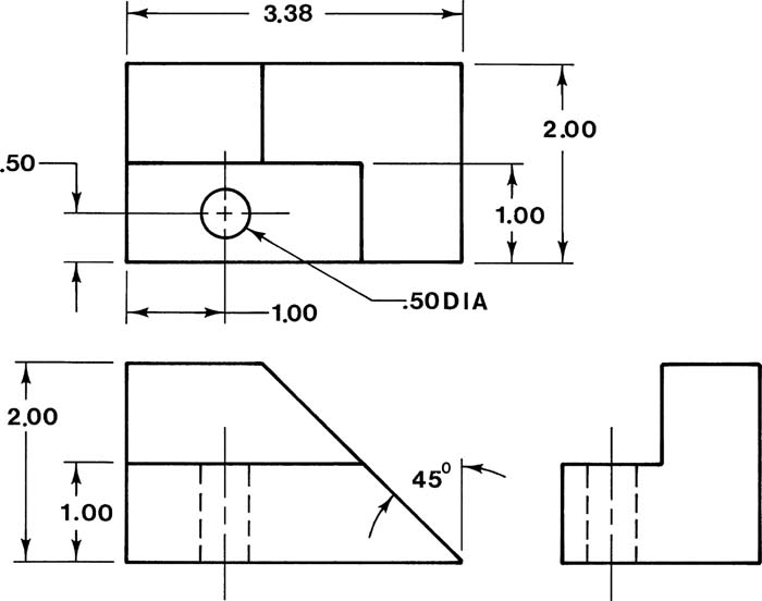
Figure 7-1 shows an object with a slanted surface that includes a hole drilled perpendicular to that surface. Note how the slanted surface is foreshortened in both the normal top and side views; also note that the hole appears as an ellipse in both of these views. The hole appears as an edge view with hidden lines in the front view, so none of the normal views show the hole as a circle.
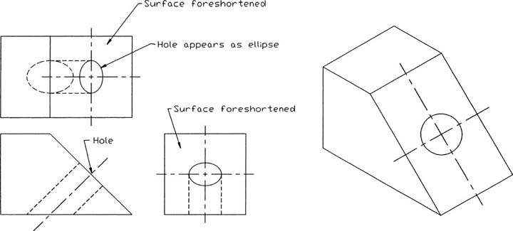
Figure 7-1
Figure 7-2 shows the same object shown in Figure 7-1. The front and side views are the same, but the top view is replaced with an auxiliary view. The auxiliary view shows the true shape of the slanted surface, and the hole appears as a circle.
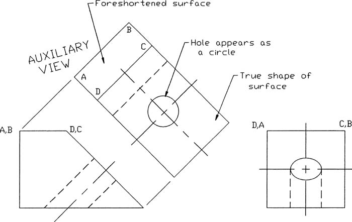
Figure 7-2
The auxiliary view in Figure 7-2 shows the true shape of the slanted surface but a foreshortened view of surface A–B–C–D. Positioning the auxiliary view to generate the true shape of the slanted surface foreshortened the other surfaces.
7-2 Projection Between Normal and Auxiliary Views
You can project information about an object’s features between the normal views and any additional auxiliary views by establishing reference planes. A reference plane RPT is located between the top and front views of Figure 7-3. The plane appears as a horizontal line, and its location is arbitrary. In the example shown, the plane was located 10 millimeters from the top view.
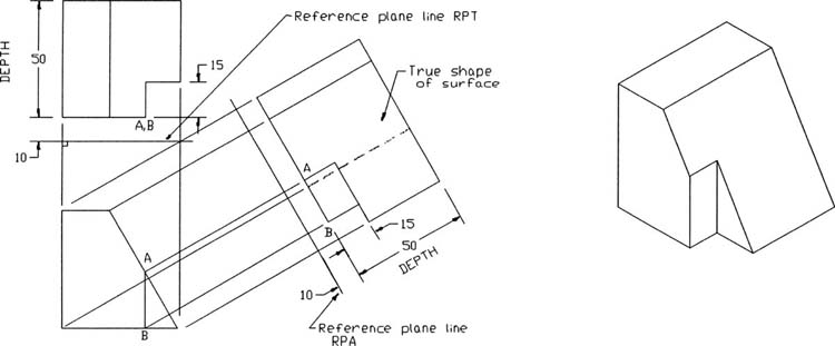
Figure 7-3
A second reference plane, RPA, is established parallel to the slanted surface at a location that prevents the auxiliary view from interfering with the top view. You can use the Move command to move the top view farther away from the front view, if necessary.
Information is projected from the front view into the auxiliary view with projection lines perpendicular to reference plane RPA.
The depth of the object is transferred from the top view to the auxiliary view. Figure 7-3 shows the 50-millimeter depth and 15-millimeter slot depth dimensioned in both the top and auxiliary views.
Figure 7-4 shows information projected from given front and side views into an auxiliary view. Reference planes RPS and RPA are located 10 millimeters from, and parallel to, the side and auxiliary views, and information is projected from the front view into the auxiliary view by lines perpendicular to plane RPA. The depth information is transferred from the side view to the auxiliary view.
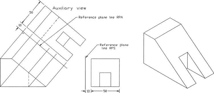
Figure 7-4
Figure 7-5 shows an object that has a slanted surface in the top view. The reference plane line, RPA, for the auxiliary view is located parallel to the slanted surface, and another reference plane, RPF (horizontal line), is established between the front and top views. Information is projected from the top view into the auxiliary view with lines perpendicular to RPA. The 30-millimeter height measurement is transferred from the front view into the auxiliary view.

Figure 7-5
Reference plane lines and projection lines drawn perpendicular to them are best drawn by rotating the drawing’s axis system, indicated by the crosshairs, so that it is parallel to the slanted surface (Figure 7-6). You can create a separate layer for projection lines.
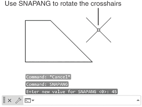
Figure 7-6
Rotating the Drawing’s Axis System
To enable easier drafting on a non-orthographic set of axes, you can use the Snapang (for snap angle) system variable to rotate the crosshairs.
Type Snapang at the command prompt.
The command prompts are as follows:
Command: SNAPANG
Enter new value for SNAPANG <0>:
Type 45 and press Enter.
The cursor rotates 45° counterclockwise (Figure 7-6). Any angle value, including negative values, may be used.
The grid also is rotated, and the Snap command limits the crosshairs to spacing aligned with the rotated axis. Ortho limits lines to horizontal and vertical relative to the rotated axis.
The angle value entered for Snapang is always interpreted as an absolute value. For example, if the procedure just described is repeated and a value of 60 is entered, the crosshairs advances only 15° from the present location or 60° from the system’s absolute 0° axis system.
7-3 Drawing Problem
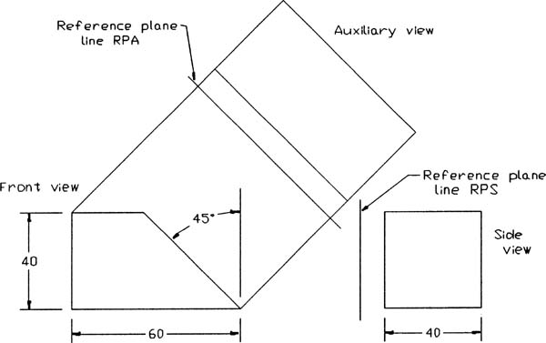
Figure 7-7 shows an object that includes a slanted surface. The front, top, and auxiliary views projected from the slanted surface were developed as follows (Figure 7-8):

Figure 7-7
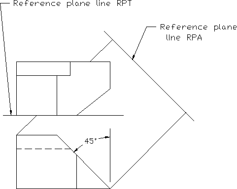
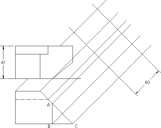

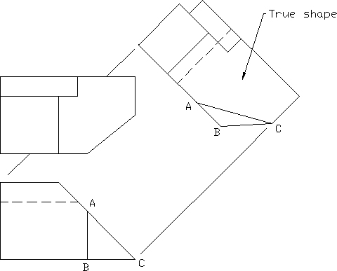
Figure 7-8
Draw the front and top orthographic views as explained in Chapter 5.
Use the Move command to position the top view so that it does not interfere with the auxiliary view.
Establish two reference plane lines: RPT parallel to the top view (horizontal line) and RPA parallel to the slanted surface (45° line).
In this example, the reference plane line for the top view is located along the lower edge of the view.
Use Snapang to establish an axis system parallel to the slanted surface. The slanted surface is 45° to the horizontal.
Turn on Ortho and draw a line parallel to the slanted surface.
Optionally create a layer for projection lines.
Project lines perpendicular to RPA from the drawing’s feature presented in the front view into the area of the auxiliary view. Use Osnap Intersection to ensure accuracy.
Type Dist in response to a command prompt to determine the distance from the reference plane line, RPT, to the object’s features.
Use Offset to draw a line parallel to RPA at a distance equal to the distances of the object’s features.
Erase and trim any excess lines and save the drawing, if desired.
7-4 Transferring Lines Between Views
Objects are often measured so that only some of their edge lines are dimensioned. This means that Offset may not be used to transfer distances to auxiliary views until the line length is known. Three methods can be used to transfer an edge line of unknown length: Measure the line length by using Dist, and then use the determined distance with the Offset command; use grips, and rotate and move the line; or use Copy, Modify, and Rotate to relocate the line. The procedures are described next.
Measuring the Length of a Line
Type Dist at the command prompt.
The command prompts are as follows:
Command: Dist
Specify first point:
Select one end of the line.
The Osnap Endpoint option helps identify the endpoint of the line. The intersection of one of the projection lines with a reference plane is usually used.
Specify second point:
Select the other end of the line.
The following style display appears in the screen’s prompt area:
Distance=40, Angle in X-Y Plane=45, Angle from the X-Y Plane=0
Delta X=28.2885, Delta Y=28.2885, Delta Z=0.0000
Figure 7-9 shows the meaning of the displayed distance information.
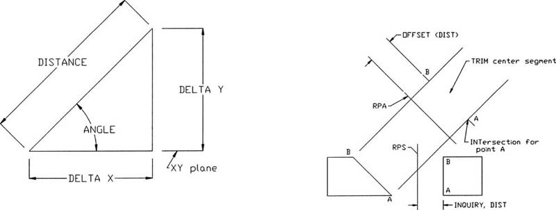
Figure 7-9
Record the distance and use it with the Offset command to locate the line’s endpoints relative to a reference plane.
Using Grips to Move a Line
Copy the line and move the copy to an open area of the drawing.
Click the line to display its grip points (refer to Section 3-15).
Select the line’s lower endpoint, right-click, and select Rotate (Figure 7-10).

Figure 7-10
**ROTATE**
Specify rotation angle or [Base point Copy Undo Reference eXit]:
Type B or click Base point at the command prompt. Select the lower endpoint as the base point.
Type 45 and press Enter.
The Dist command can also be used to determine the angle of a slanted surface if it is not known. Note that the angle value returned depends on which of the endpoints is selected first.
Select the line’s lower endpoint again.
Select Move from the right-click menu.
Select the lower endpoint as the base point.
Move the line to a new location or use dynamic input to define a new location.
Rotating and Moving a Line
Copy the line and move the copy to an open area of the drawing.
Select Rotate from the Modify panel and rotate the line 45° (refer to Section 3-15).
Select Move from the Modify panel and relocate the line to the auxiliary view. Use Osnap, if necessary, to ensure accuracy.
7-5 Drawing Problem
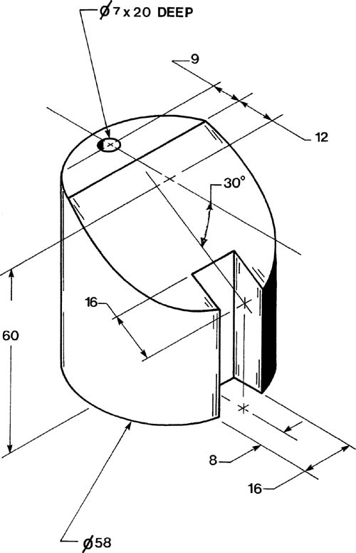
Figure 7-11 shows an object that contains two slanted surfaces and two cutouts. Draw front and right-side orthographic views, as well as an auxiliary view (Figure 7-12).
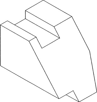
Figure 7-11


Figure 7-12
Draw the front and side orthographic views as described in Chapter 5.
Define a reference plane, RPS, between the front and side views.
Use Snapang (37.5) to align the crosshairs with the slanted surface. The 37.5° value was determined by using the Dist command.
Draw a reference plane line, RPA, parallel to the slanted surface, and project the features of the object into the auxiliary view area.
Transfer the distance measurements from RPS and the side view into the auxiliary view. Label the various points as needed.
Erase and trim any excess lines and save the drawing, if desired.
7-6 Projecting Rounded Surfaces
Rounded surfaces are projected into auxiliary views in the same way they are projected into the orthographic views as described in Chapter 5, Section 5-15. Additional lines are added to one of the orthographic views and then projected into the other orthographic view. The additional lines define a series of points that define the outside shape of the surface. The two views with the added lines project and transfer the points into the auxiliary view.
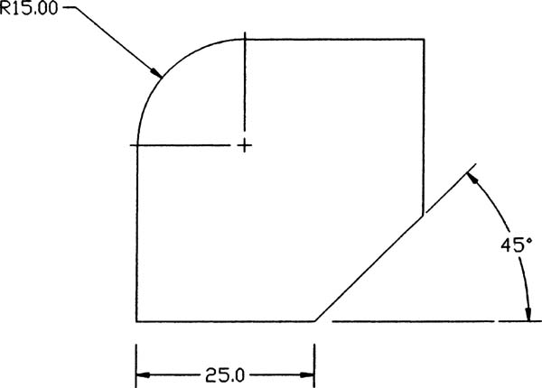
7-7 Drawing Problem
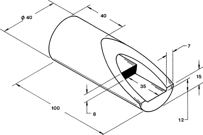
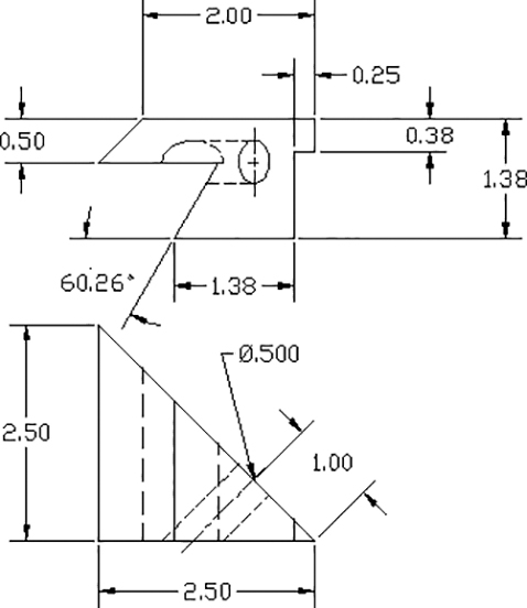
Figure 7-13 shows a cylindrical object that includes a slanted surface. Draw the front, side, and auxiliary views (Figure 7-14).
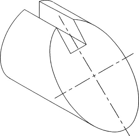
Figure 7-13

Figure 7-14
Draw the front and side orthographic views.
Draw a reference plane line, RPS.
In this example, the reference plane line is the side view’s vertical centerline.
Draw a reference plane line, RPA, parallel to the slanted surface. The reference plane line will also be used as the centerline for the auxiliary view.
In this example, the endpoints of both the major and minor axes of the projected elliptical auxiliary view are known, as is the angle of the auxiliary view. It is therefore not necessary to define points in the circular side view, as was done in Section 5-21. Enough information is present to draw the elliptical shape directly in the auxiliary view.
Draw the elliptical surfaces in the auxiliary view, as shown.
Transfer the width and location of the slot from the side view to the auxiliary view.
Erase and trim any excess lines and save the drawing, if desired.
7-8 Projecting Irregular Surfaces
Auxiliary views of irregular surfaces are created by projecting information from given normal orthographic views into the auxiliary views in a manner similar to the way information is projected between orthographic views (refer to Section 5-9). The irregular surface is defined by a series of points along its edge line. The locations of the points are random, although more points should be used when the curve’s shape is changing sharply than when the curve tends to be smoother.
7-9 Drawing Problem
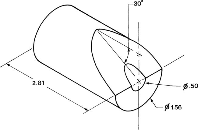
Figure 7-15 shows an object that includes an irregular surface. Draw front and side orthographic and auxiliary views of the object (Figure 7-16). The procedure is described below.
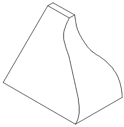
Figure 7-15
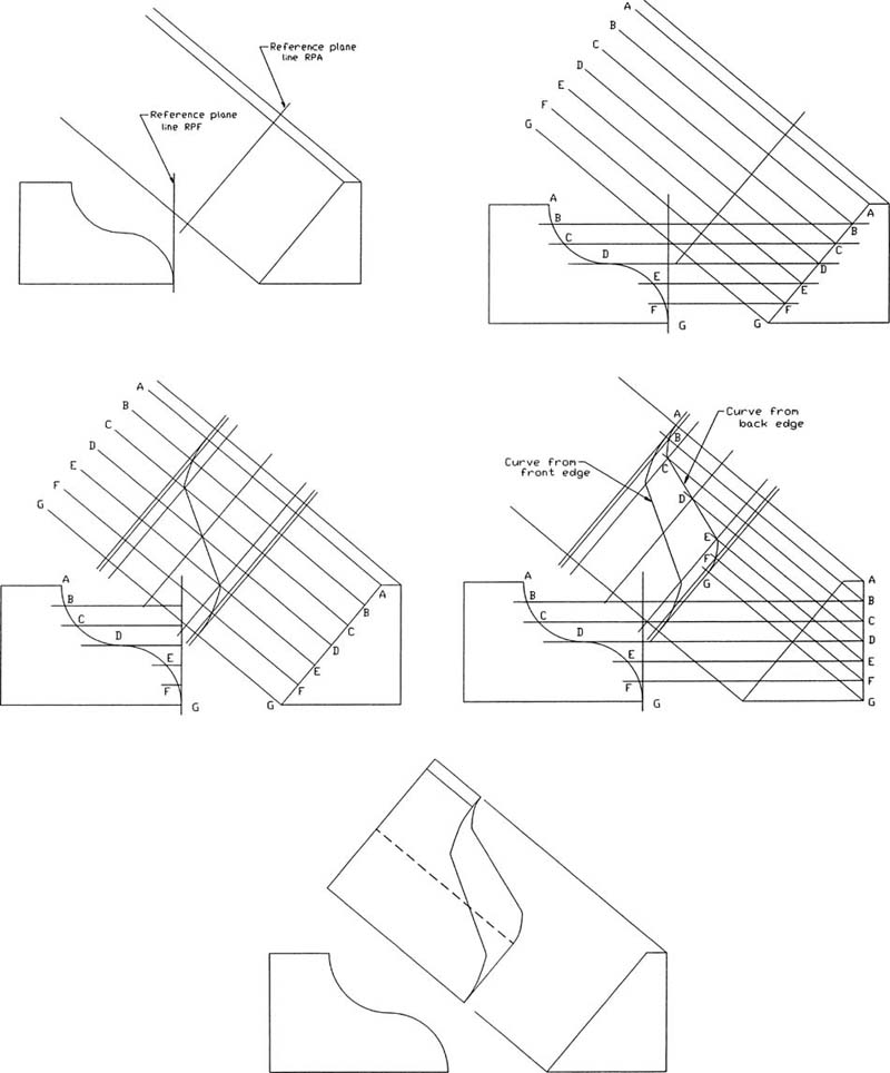
Figure 7-16
Draw a front view and a side view.
Draw two reference lines: RPF between the front and side views and RPA parallel to the slanted surface in the side view.
Use Snapang to align the crosshairs with the slanted surface.
Define points along the irregular surface edge line in the front view and project the points into the side view by using horizontal lines.
Project the points into the auxiliary view, using lines perpendicular to line RPA. Label the points and their projection lines.
Transfer the depth measurements from RPS and the object’s features, as well as the points defining the irregular curve, to the auxiliary view.
Type Dist in response to a command prompt to determine the distance from RPF to the points.
Use Offset to draw lines parallel to RPA.
Use Polyline, Edit Polyline, and Fit to draw the irregular curve required in the auxiliary view. Use Edit Vertex to smooth the curve, if necessary.
Project the points defined in the front view to the back surface (far-right vertical line) in the side view and project the points into the auxiliary view.
Use Polyline, Edit Polyline, and Fit to draw the required irregular curve.
Erase and trim any excess lines and save the drawing, if desired.
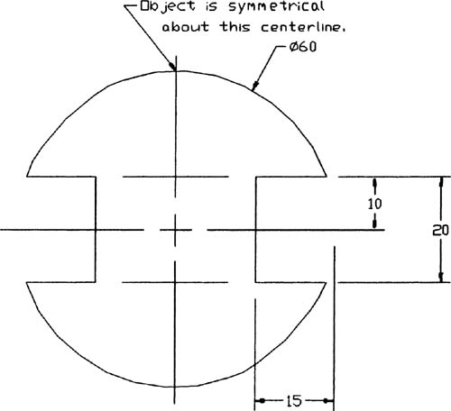
7-10 Drawing Problem
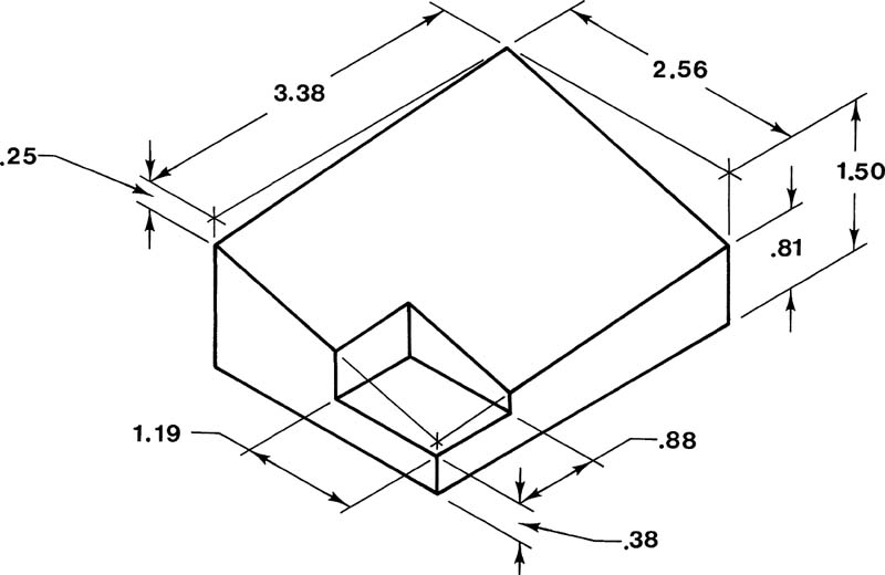
Figure 7-17 shows an isometric view of a block with a triangular notch. The notch depth is not consistent, and the notch is not parallel to any of the sides. Figure 7-18 shows a top view and an auxiliary view of the object. Redraw the given views and add the front and right-side views. The procedure is described as follows.

Figure 7-17

Figure 7-18
Draw a reference plane line, RPA, parallel to the auxiliary view and a reference plane line, RPT, a horizontal line.
The object contains a dihedral angle (an angle between two planes), and the auxiliary view has been aligned with the vertex line of the angle. Reference plane RPA is perpendicular to the vertex of the dihedral angle’s vertex.
Project information from the top view and transfer information from the auxiliary view into the front view.
Project information from the front view and transfer information from the top view into the side view.
Erase and trim any excess lines and save the drawing, if desired.
7-11 Partial Auxiliary Views
Auxiliary views present true views of slanted and oblique surfaces, but in doing so, they generate foreshortened views of other surfaces. It is often clearer to create an auxiliary view of just the slanted surface and omit the surfaces that would be foreshortened. An auxiliary view that shows only one surface of an object is called a partial auxiliary view.
Figure 7-19 shows a front view and three partial views of the object: a partial top view and two partial auxiliary views. A broken line (refer to Section 6-14) may be used to show that the partial auxiliary view is part of a larger view that has been omitted. Likewise, hidden lines may or may not be included. Figure 7-20 shows a front view, a side view, and two partial auxiliary views of an object. Both the hidden lines and broken lines were omitted. If you are unsure about the interpretation of a view with hidden lines omitted, add a note to the drawing next to the partial views that says ALL HIDDEN LINES OMITTED FOR CLARITY.

Figure 7-19
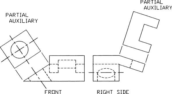
Figure 7-20
7-12 Sectional Auxiliary Views
Sectional views may also be drawn as auxiliary views. Figure 7-21 shows an auxiliary sectional view. The cutting plane line is positioned across the object. A reference plane line is drawn parallel to the cutting plane line, and information is projected into the auxiliary sectional view by use of lines perpendicular to the cutting plane line.
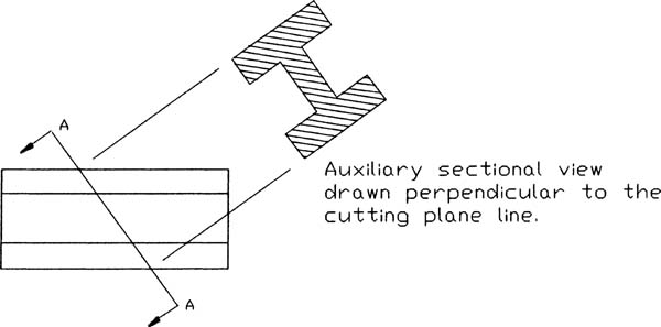
Figure 7-21
Figure 7-22 shows front, partial auxiliary, and auxiliary sectional views of an object. In this example, the partial sectional view was used to help clarify the shape of the object’s feature that would appear vague in the normal top or side views.
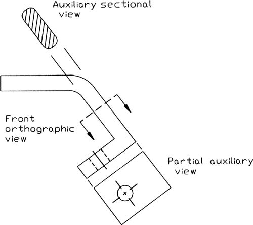
Figure 7-22
7-13 Auxiliary Views of Oblique Surfaces
The true shape of an oblique surface cannot be determined by a single auxiliary view taken directly from the oblique surface. An auxiliary view shows the true shape of a surface only when it is taken at exactly 90° to the surface.
A slanted surface is a surface that is rotated about only one axis (Figure 7-23). One of the orthographic views must be an edge view of the surface (i.e., the surface appears as a line) for an auxiliary view created by projecting lines perpendicular to that view to show the true shape of the surface.

Figure 7-23
An oblique surface is a surface that is rotated about two axes (Figures 7-23 and 7-24). This means that none of the normal orthographic views will show the oblique surface as an edge view; there is no given end view of the surface. This, in turn, means that an auxiliary view taken directly from one of the given views will not be perpendicular to the surface and therefore will not show the true shape of the surface. An auxiliary view that shows an edge view of the surface must first be created; then a second auxiliary view taken perpendicular to one of the other normal orthographic views is needed to show the true shape of the surface.

Figure 7-24
7-14 Secondary Auxiliary Views
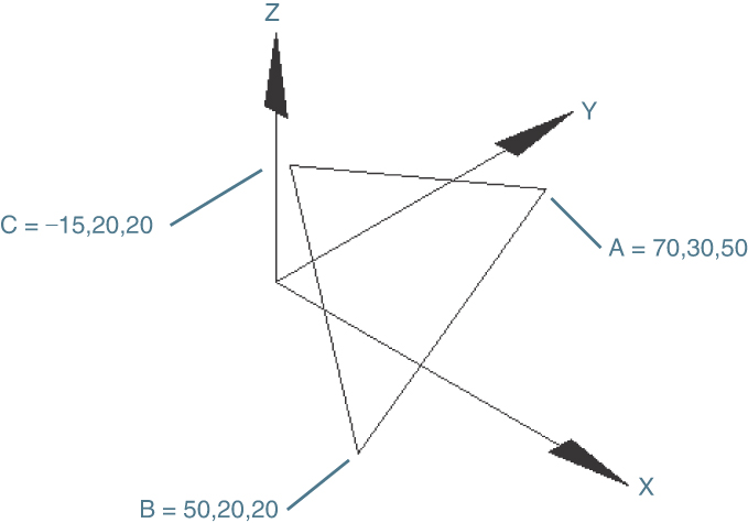
Consider the object shown in Figure 7-25. What is the true shape of surface A–B–C? An auxiliary view taken perpendicular to the surface will show its true shape, but what is the angle for a plane perpendicular to the surface?

Figure 7-25
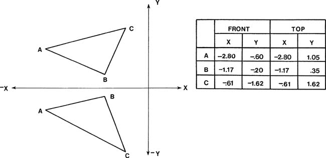
Figure 7-26 shows the normal orthographic views of the object.
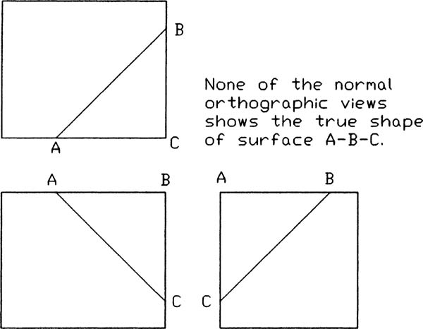
Figure 7-26
Start by choosing an edge line in the plane that is perpendicular to either the X or Y axis. Edge line A–B in the front view is a horizontal line, so it is parallel to the X axis. Take an auxiliary view aligned with the top view of the edge line (you’re looking straight down the line). This auxiliary view will be perpendicular to the edge line and will generate an end view of the plane. A second auxiliary view can then be taken perpendicular to the end view that will show the true shape of the surface.
Figure 7-27 shows how a secondary auxiliary view is created for the object shown in Figure 7-25. The specific procedure is described next.
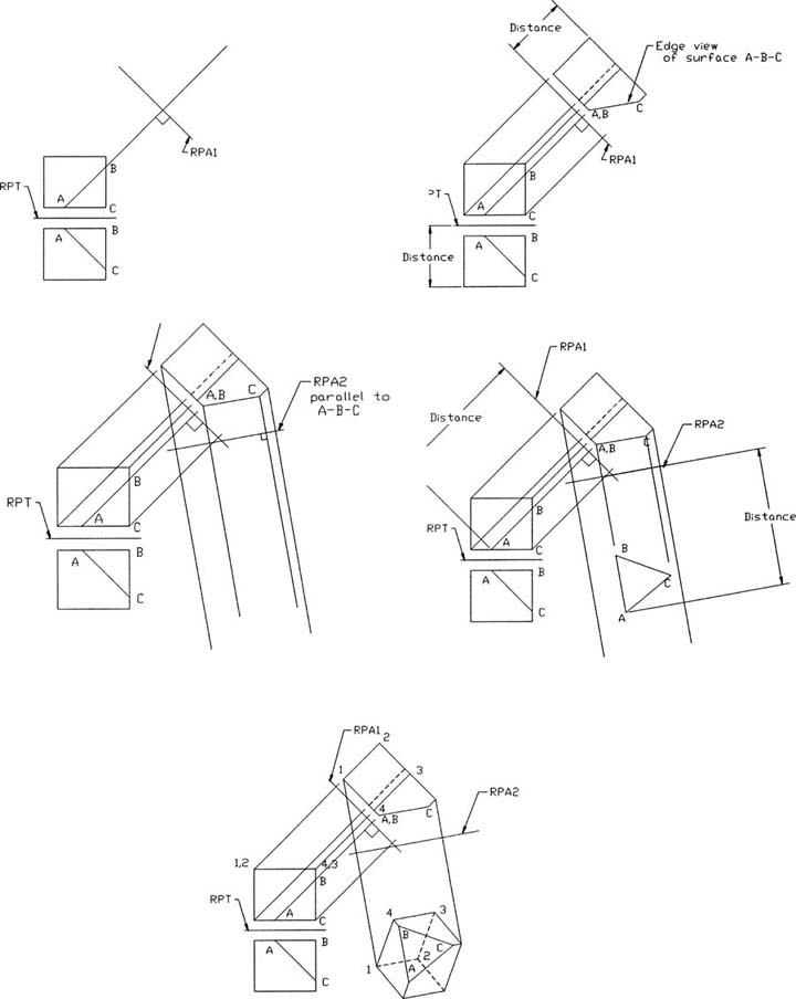
Figure 7-27
Drawing the First Auxiliary View
Draw the normal orthographic views of the object.
Draw a reference plane, RPT, between the front and top views.
Extend a line from the top view of line A–B in the area for the first auxiliary view.
Use the Extend command to draw a construction line slightly beyond the expected area of the first auxiliary view, then use the construction line as an Extend boundary line (refer to Section 2-23), and extend line A–B to the boundary. Erase the construction line.
Draw a reference plane line, RPA1, perpendicular to the line A–B extension.
Use Snapang to align the crosshairs with the extension line. Use the Dist command to determine the line’s angle if it is not known.
Project the slanted surface of the object into the auxiliary view by using lines perpendicular to RPA1.
Transfer the distance measurements from RPT and the front view as shown at top right in Figure 7-27.
Erase and trim any excess lines and create the first auxiliary view.
The surface A–B–C should appear as a straight line. This is an edge view of surface A–B–C.
Drawing the Secondary Auxiliary View
Use Snapang and align the crosshairs with the end view of surface A–B–C. Use Dist to determine the angle of the edge view line.
Draw a reference plane line, RPA2, parallel to the edge view of the surface (Figure 7-27, center left).
Project the features of the object into the second auxiliary view, using lines perpendicular to RPA2 (Figure 7-27, center right).
Transfer the distance measurements from RPA1 and the top view as shown in Figure 7-27, bottom.
Erase and trim any excess lines and save the drawing, if desired.
The secondary auxiliary view shows the true shape of surface A–B–C.
Figure 7-28 shows another example of a secondary auxiliary view used to show the true shape of an oblique surface. In this example, the first auxiliary view was taken from line F–A in the front view because it is a vertical line in the side view. The distance measurements came from the top view. The procedure used is the same as described previously.
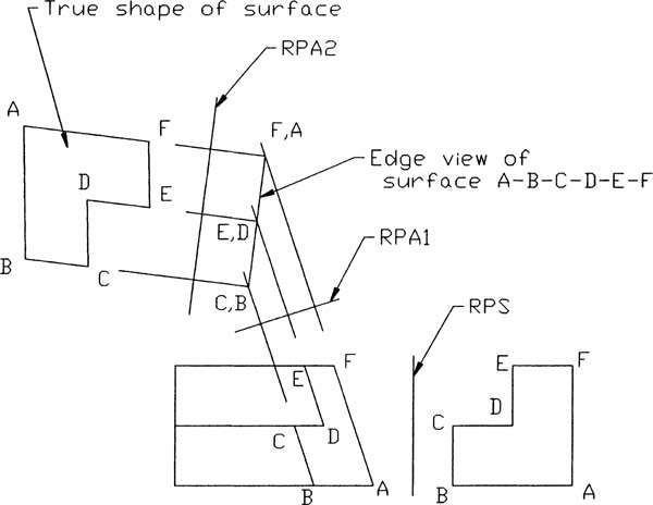
Figure 7-28
The auxiliary view shown in Figure 7-28 includes only the oblique surface. This is a partial auxiliary view. The purpose of the auxiliary view is to determine the true shape of the oblique surface. All of the other surfaces would be foreshortened, not showing their true shape, if included in the auxiliary views.
7-15 Drawing Problem
What is the true shape of the plane shown in Figure 7-29?
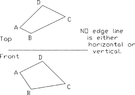
Figure 7-29
None of the edge lines are horizontal or vertical lines, so a line that is either horizontal or vertical must be added. In Figure 7-29, a horizontal line is added between the top and front views, and can then be used to generate the two auxiliary views needed to define the true shape of the plane.
The procedure is as follows (Figure 7-30):
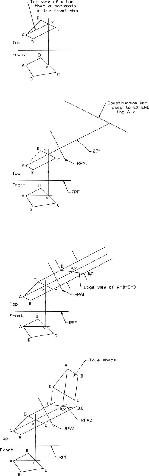
Figure 7-30
Draw a horizontal line from point A in the front view.
Use Osnap Intersection with Ortho on and draw the line across the view. Use Trim to remove the excess portion of the line.
Define the intersection of the new line with one of the plane’s edge lines (D–C) as x.
Project line A–x into the top view.
Optionally, create a layer for projection lines.
The location of point A is already known in the top view. The location of point x in the top view is found by drawing a vertical line from point x in the front view so that the line intersects line D–C in the top view. Use Osnap Intersection with Ortho on to ensure accuracy.
Extend line A–x into the area for the first auxiliary view.
Draw a construction line to use as a boundary line for the Extend command.
Draw two reference plane lines: RPT between the front and top views, and RPA1, perpendicular to the extension of line A–x.
Use Snapang to align the crosshairs with the extension of line A–x.
Project the plane’s corner points into the area of the first auxiliary view from the top view. Transfer the distance measurements from RPT and the front view.
Use Dist to determine the distance from RPF and the corner points of the surface. Use Offset to transfer the point distance from RPF to RPA1. Use Trim to remove the internal portion of the offset lines. This helps clarify the drawing by removing excess lines from the auxiliary view, but you can retain intersection points needed to draw lines by using Osnap Intersection.
The end view of the plane should appear as a straight line.
Draw a third reference plane line, RPA2, parallel to the end view of the plane, and project the plane’s corner points into the secondary auxiliary view area.
Transfer the depth distances from RPA1 and the top view to RPA2 and the secondary auxiliary view.
Erase and trim any excess lines and save the drawing. if desired.
The secondary auxiliary view shows the true shape of surface A–B–C–D.
7-16 Secondary Auxiliary View of an Ellipse
Figure 7-31 shows the front and side views of an oblique surface and includes a foreshortened view of a hole—that is, an ellipse. Also included are two auxiliary views, the second of which shows the hole as a circle.

Figure 7-31
The ellipse is projected by first determining the correct projection angle that produces an edge view of surface A–B–C–D. In this example, line B–C appears as a vertical line in the side view, so its front view can be used to project the required edge view.
It is known that the secondary view of the surface shows the hole as a circle, so only a radius value need be carried between the views. In this example, point 1 in the front view was projected into the first auxiliary view and then into the second auxiliary view, thereby defining the radius of the circle.
The hole is located at the center of the surface, which means that its centerlines are located on the midpoints of the edge lines in the secondary auxiliary views. If the hole’s center point were not in the center of the surface, the intersections of the hole’s centerlines with the surface’s edge lines would also have to be projected into the secondary auxiliary view to accurately locate the hole.
7-17 Exercise Problems
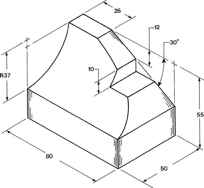
Given the outlines for front, side, and auxiliary views shown in Exercise Problem EX7-1, substitute one of the side views shown in Exercise Problems EX7-1A through EX7-1D and complete the front and auxiliary views. All dimensions are in millimeters.
EX7-1
EX7-1A

EX7-1B

EX7-1C

EX7-1D
Given the outlines for front, side, and auxiliary views, as shown, substitute one of the side views shown in Exercise Problems EX7-2A through EX7-2D and complete the front and auxiliary views. All dimensions are in millimeters.
Draw two orthographic views and an auxiliary view for each of the objects shown.
EX7-2

EX7-2A

EX7-2B
EX7-2C

EX7-2D

Draw two orthographic views and an auxiliary view for each of the objects in Exercise Problems EX7-3 through EX7-6.
EX7-3 Millimeters
EX7-4 Millimeters
EX7-5 Inches

EX7-6 Millimeters
Redraw the given orthographic views in Exercise Problems EX7-7 through EX7-10 and add the appropriate auxiliary view.
EX7-7 Millimeters

EX7-8 Millimeters
EX7-9 Inches

EX7-10 Millimeters

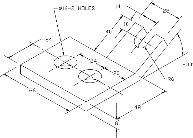
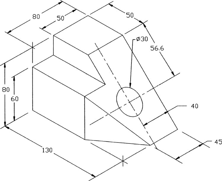
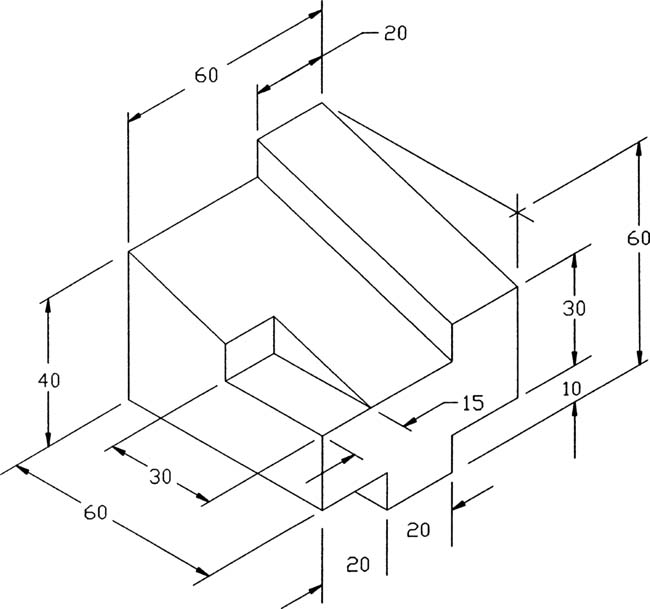
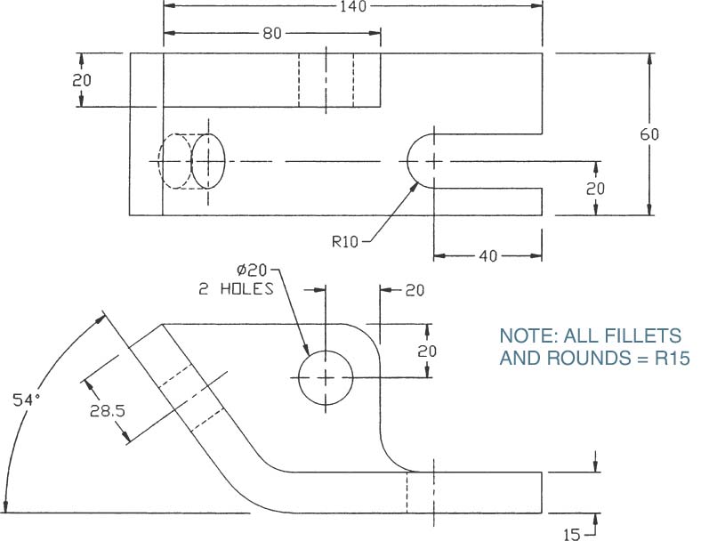
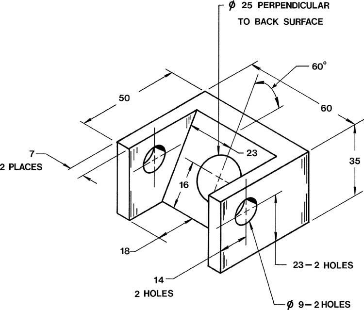
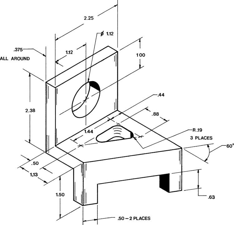
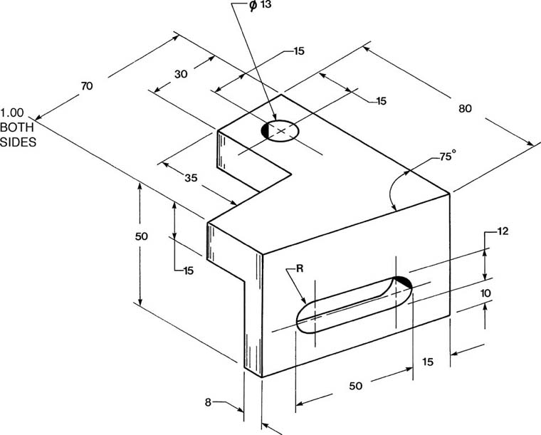
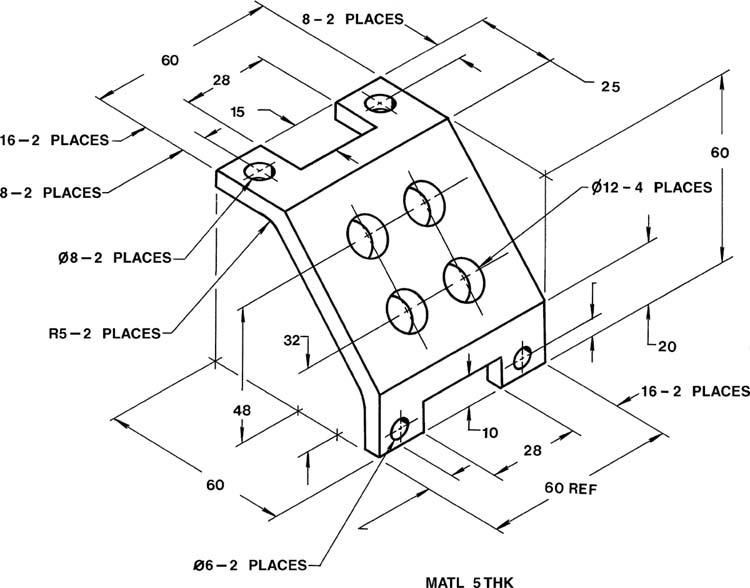
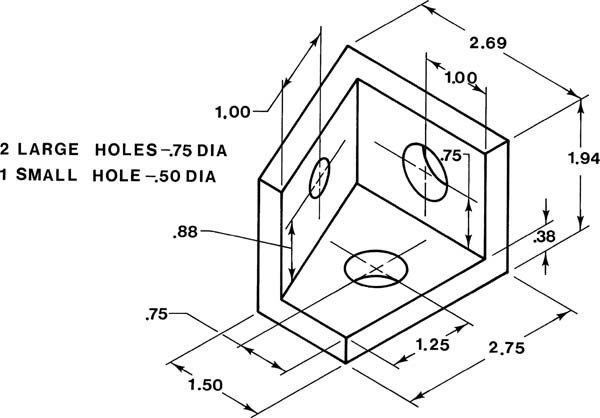
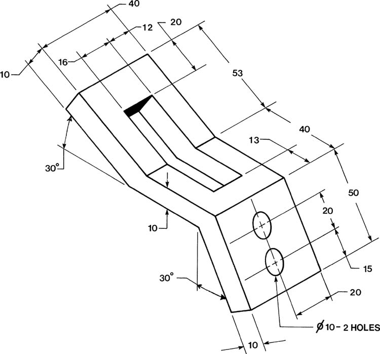
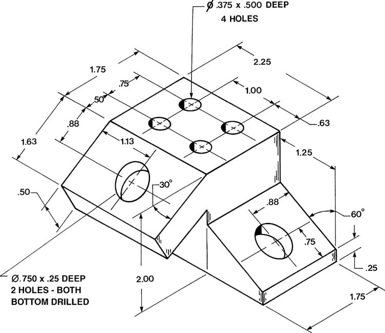
Draw two orthographic views and an auxiliary view for each of the objects in Exercise Problems EX7-11 through EX7-40.
EX7-11 Millimeters

EX7-12 Millimeters

EX7-13 Millimeters

EX7-14 Millimeters
EX7-15 Inches

EX7-16 Inches
EX7-17 Millimeters
EX7-18 Millimeters
EX7-19 Millimeters
EX7-20 Inches
EX7-21 Millimeters

EX7-22 Millimeters
EX7-23 Inches

EX7-24 Millimeters

EX7-25 Inches
EX7-26 Millimeters

EX7-27 Millimeters

EX7-28 Millimeters

EX7-29 Millimeters

EX7-30 Millimeters
EX7-31 Inches
EX7-32 Millimeters
EX7-33 Millimeters
EX7-34 Millimeters

EX7-35 Millimeters

EX7-36 Inches

EX7-37 Inches
EX7-38 Inches

EX7-39 Millimeters

EX7-40 Millimeters
Draw at least two orthographic views and one auxiliary view for each of the objects in Exercise Problems EX7-41 through EX7-44.
EX7-41 Inches
EX7-42 Inches
EX7-43 Inches
EX7-44 Inches

Use a secondary auxiliary view to find the true shape of the planes in Exercise Problems EX7-45 through EX7-50.
EX7-45 Millimeters
EX7-46 Millimeters

EX7-47 Millimeters

EX7-48 Inches (Scale: 4:1)

EX7-49 Millimeters (Scale: 2:1)

EX7-50 Inches (Scale: 3:1)
EX7-51 Millimeters

Redesign the given object to include two Ø10 holes in the slanted surface. The holes should be centered along the longitudinal axis, and spaced so that the distance between the holes’ centers equals the distance from the holes’ centers to the upper and lower edges of the slanted surface. The holes should be perpendicular to the slanted surface.
Draw the front, top, and side views of the object, plus an auxiliary view of the slanted surface. Include the new holes in the slanted surface.
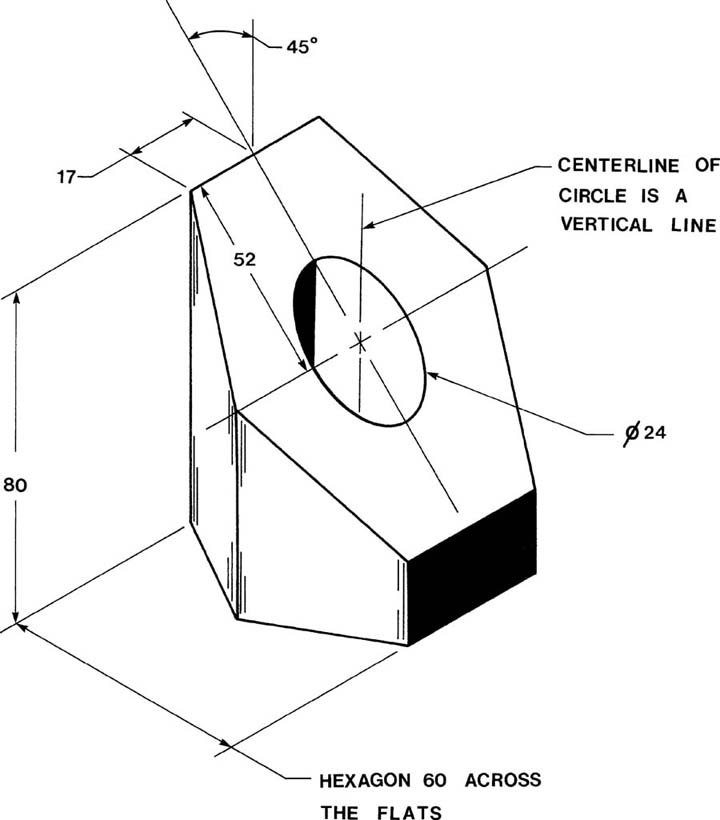
EX7-52 Millimeters
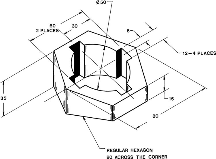
Redesign the given object so that the outside shape is a regular heptagon (seven-sided polygon) 80 across the flats, with the inside Ø50 hole intersected by six evenly spaced slots each 12 wide. Draw front and top orthographic views and an auxiliary view of the object.
EX7-53 Millimeters

Calculate the area of the given plane. Redesign the plane so that the new plane is congruent to the original but has an area equal to 1.5 times that of the original area. Draw and label the true shape of the new plane relative to the X, Y, and Z axes.