There is no exact term, per se, for objects that cast light in a game. So, I'll just refer to such objects as illuminators. Sounds cool, don't you think? Illuminators are created the same way as other objects in that they are modeled, UV mapped, textured, and so on. The main difference is that illuminators are utilized as light sources and should have some sort of illuminating ability, whether it is a light bulb or magical innate glow of subterranean mushrooms. In this chapter, you'll create a simple illuminator and learn about the differences between illuminators and other, non-illuminating objects.
In most game engines, a light source is not a piece of game art. That is, when you see a glowing light bulb model in a video game, the light being cast from that model is not coming from the model at all but from an invisible object that is created and placed within the game engine (usually by a level designer but possibly by a skilled lighting artist). I'll refer to this invisible object as a light source. The light source and the illuminator are two separate things. The illuminator is the object that is meant to represent the light source, and that is what this chapter focuses on.
Note
There are a few game engines (such as the more current versions of the Unreal Engine) out there that are able to recognize the glow from an illuminator object and dynamically create a light source from it. But for most game engines, that isn't the case.
This is much the same as it is in Maya. You could model a light bulb with all the necessary components for illumination—the filament, the wires, the insulation, and so on—yet it still cannot turn on. It isn't real, after all. So, you must create a light source from the assortment of lights that Maya provides. Point lights, directional lights, area lights—all created from the ether to provide illumination. These are the sources of the light. The light bulb model is simply the illuminating object—the illuminator.
For this chapter, you'll create a light sconce. The sconce is modeled, UV'd, and textured much the same way as you have done for the other projects in this book; however, this time, you'll add one additional texture type—the emissive map or "glow" map.
The emissive map can either be grayscale or have color. If the map is grayscale, the color of the glow can sometimes be tinted with controls found in the game engine being used. Otherwise, the glow will be white. If the emissive map is colored, the glow will be of the same hue. Before you get too far into the ins and outs of the emissive map, first you need to create the model.
Just as in the previous projects, you'll begin with creating a model of the wall sconce. This sconce will be a flared square shell design. Modeling the light bulb itself may not be necessary if the sconce is always on and glowing: The bright glow from the light can hide the interior of the lamp and therefore hide the bulb. If the sconce can be turned off, however, the interior may be visible and the bulb displayed. For such cases, the bulb would need to be created.
First, create a cube that is 3 units wide, 5 units tall, and about 0.25 units deep. This will be the wall bracket.
Line the cube up so that the back is even with the origin. The origin line will act as the "wall" that the sconce is attached to.
Select the four corner edges and bevel them. If you are following along with my scale, the default Offset value should work fine.
Select the beveled edges (all eight of them) and bevel them again. This time, decrease the Offset down to 0.1.
Select the front face and bevel it, decreasing the Offset to about 0.2.
Use the Extrude and Bevel commands to create three tiers to the wall bracket, as in Figure 6.1.
In the side view, create a tall cube that is 3 units tall, and 1.5 units wide and deep. Increase the Subdivisions value to be 5 along the height of the cube. These subdivisions will allow the cube to be flared in the following steps.
Change the menu set to Animation, which gives you access to the animation class of menus. Select the new cube, if it isn't selected already, and select Create Deformers → Nonlinear → Flare. This will apply a Flare deformer to the cube.
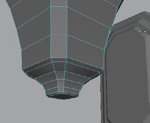
Increase the End Flare X and Z values to 2 to flare out the top of the cube. Modify the Curve value until you have the curvature that you want for the sconce (Figure 6.2).
When you have a shape you are happy with, delete the sconce's history. This will remove the Flare deformer and finalize the shape change.
Bevel the vertical edges of the sconce, adjusting the Offset to about 0.3.
Select the top and bottom faces of the sconce and bevel them as well, using an Offset of approximately 0.15.
At this point, you may want to rescale the sconce in relation to the wall bracket. I scaled mine slightly shorter and a tad wider.
Select the bottom face and extrude it down about 0.25 units and scale it inward a bit to curve the edges toward the center. Select the bottom face again and extrude down about 0.5 units. Scale it inward to about half the original width.
In the Channel Box, scroll down to the bottom of the most recent Extrude's options to the Divisions value. Increase the Divisions to 3, adding some horizontal cuts to the extruded shape. Select the middle row of edges (or faces) and, locking the y-axis, scale your selection inward to curve the shape as in Figure 6.3. You can slightly bevel the bottom face.
Select the eight vertical edge loops on the corners of the sconce and bevel them slightly to soften their sharpness.
Using the Insert Edge Loop tool (from the Edit Mesh menu in the Polygons menu set), insert four edges that form the boundary for the selection of faces you can see in Figure 6.4. This is for the opening that the light will shine through.
When you have the window faces created, select them and extrude them inward slightly. Scale the extrusion in to create a beveled edge to form the lip of the window. Then, extrude again, this time extruding deeper into the sconce.
Instead of doing this extrusion process four times, to keep all four sides identical, you can delete the other four sides' faces and duplicate the edited side. Delete the other three sides, being sure to leave the top and bottom faces. Don't duplicate the fourth, remaining side just yet. You're not quite done with it.
At this point, rather than having flat corners, you can add any decorative details that you like. I'm going to add a rounded ridge up the center of the corner faces.
Using the Insert Edge Loop tool, insert three vertical edge loops up the center, left, and right sides of one of the corner surfaces.
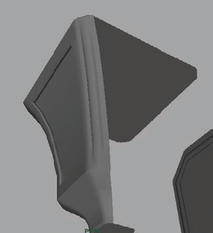
Select the edges in the center, next to the window cavity, and move them outward. To soften the edge here, you can bevel your selection (Figure 6.5).
Create three duplicates of the remaining side of the sconce and rotate them around for the missing sides. Delete any faces you don't need and combine them together, merging the edges where they meet.


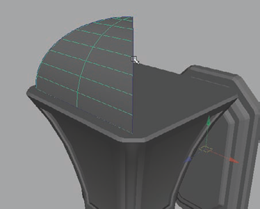
To cap the sconce, you'll add a domed shape that the light can escape through. It'll follow the main shape's design in that it will have a square base. To start, you'll use curves to create a quarter of the shape and then duplicate it for the remainder.
In the Top view, create a circular curve by selecting Create → NURBS Primitives → Circle. Scale it up to encompass the entire sconce but have it cross over the tops of the sconce's corners.
Rotate it 90 degrees along the x-axis to stand vertical, and 45 degrees in the y-axis to point it diagonally from corner to corner. Position it so that it is halfway inserted into the sconce. If you need to, scale the circle up so that it extends across the sconce at the corners.
Scale the circle down in the y-axis slightly to squash it a bit. You can see what I mean in Figure 6.6.
Select the circle and look for the Sweep Input value found in the Channel Box under the makeNurbCircle1 node. Decrease the Sweep value to 90. This makes the curve only extend 90 degrees rather than the full 360 degrees.
Duplicate it and rotate the duplicate 90 degrees to form a wedge shape with the two curves.
Next, you'll create a third curve that connects the two wedge curves at their base. Select the CV Curve tool from the Create menu. Hold down the C key to toggle Snap To Curve mode and middle-click and drag on one of the curves. A point will appear on the curve, following your cursor. Move the point down to the bottom of the curve and release the middle-mouse button.
With the C key still being held down, middle-mouse click and drag on the other curve, dragging a point down to the base of it. Release the C key and the middle mouse button and press Enter to finish the curve.
This is the perfect opportunity to use a new tool, the Birail tool. Switch your menu sets to Surfaces. From here, select Surfaces → Birail → Birail 1 Tool → Options. In the options, change the following settings:
Output geometry
Polygons
Type
Quads
Tessellation method
General
U type and V type
Per span # of iso params
Number U and V
1
With the Birail 1 tool active, simply follow the onscreen prompts found down in the Help Line at the bottom left of the screen. I'll also walk you through it here:
First, select the Profile curve. That would be the line that connects the two rounded "Rail" curves at their base.
Next, select the two Rail curves.
Watch in amazement as the surface appears!
You should have a shape similar to Figure 6.7 appear.
In the Channel Box, under the nurbs Tessellate1 Input item, increase the V Number value to about 12. This will add a lot of geometry to the surface, but it will give you the ability to create another window cavity for the light that will eventually shine through.
First, delete the tip of the geometry wedge where all of the faces come to a point. Then, select all the faces in the center of the wedge of geometry, leaving the outer row of faces unselected. Delete the selected faces. You should have a frame of faces remaining, as you see in Figure 6.8. You can delete the edges that are left over along the top and bottom faces (using the Delete Edge/Vertex command from the Edit Mesh menu).
Duplicate the frame around to make the other three sides of the shape. Combine and merge them together.
Use the Select Edge Loop tool from the Select menu and double-click an edge from each of the four corners to select the vertical edge loops on each corner. Apply a Bevel to them to round off the hard edges. Feel free to increase the Segments value to 2 if they don't seem rounded enough for your tastes.
Select the entire frame and extrude it about 0.1 units, giving the entire object some thickness.
In the Front view, use the CV Curve tool to draw the profile shape for a decorative top for the dome. It can be whatever shape you like. Make sure your first and last points are on the origin line (toggle grid snap by holding the X key if you need to). Mine is sort of chess-piece-shaped, like you see in Figure 6.9.
Note
You only need the profile curve to form one half of the shape you want, not the entire thing.
Once you have the profile shape you like, switch your menu set to Surfaces and select Surfaces → Revolve → Options. In the options, make certain that you are using the polygon output settings that you set back in step 8. When your settings are correct, click the Revolve button.
If you want to adjust your shape after revolving, you can simply adjust the control vertices of the profile curve and the history that is still present on the mesh will update its shape in real time. Once you are happy with the revolved results, you can delete the history on the revolved shape and delete the profile curve.
You can use the same process to create another decorative piece at the base of the sconce as well, or you can create a cylinder and use a series of Extrudes and Bevels to get the results you want. With whichever process you decide to use, make sure to create it with the same style as the one on top of the sconce so that they match stylistically. You can see how mine looks in Figure 6.10.
Next, you can fill in the space on the dome by creating the glass that will be illuminated in a later step. This can easily be done by using the Snap To Point command while creating the polygon using the Create Polygon tool.
Hold the V key to toggle Snap To Point and use the points along the inner edge loop of the dome frame to create the glass surface. Duplicate it to fill in the dome on the other three sides. (Figure 6.11)


The sconce shape is pretty much in place, so now you can work on creating the attachment to the wall bracket. This can, of course, be done any number of ways with whatever style you choose. I'll be using a decorative vine-like design.
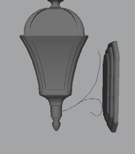
In the Side view, use the CV Curve tool to draw out an arcing curve from the base of the sconce to the top of the forward-facing surface of the wall bracket.
Draw another curve starting from the lower middle half of the first curve and curve it into a loop that flows near the lower part of the wall bracket.
You can edit these curves to shape them however you'd like. Mine look like Figure 6.12.
Once you have the path curves shaped the way you like, you can create a profile curve. It could be just a simple circle, but for the sake of visual interest, you could create a more interesting shape. If you'd like to follow along with me, first create a NURBS circle from the Create → NURBS Primitives menu.
Double the circle's Sections value to 16. With the increased points on the circle, you have more control to edit the shape. I manipulated mine to look sort of mushroom-shaped, like in Figure 6.13.
Select the profile curve and Shift-select one of the path curves. Within the Surfaces menu set, choose Surfaces → Extrude. Do it a second time with the other path curve.
At this time, you can modify the path curve points to continue to adjust the vine-like shapes to your liking. You'll want them to be at equal distances from the bracket, with about an inch or two of space between them.
Note
You should have already set the polygonal output settings for the Extrude from a previous step, but in case you haven't, make certain you use the settings found in step 8 of the prior section in the Extrude options.
Select the edges that border the end of one of the vine-like objects and use the Mesh → Fill Hole command to fill it in with a polygon.
Select the new face and use the Extrude command to extend and taper the end of the shape. You can also scale the existing edge loops to smoothly taper the end of the surface. Do the same for the other (Figure 6.14).
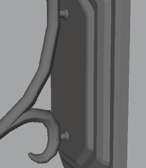
Once you are happy with the shape of the connector shapes, you can create a simple cylinder with a beveled lip to serve as the connection between them and the bracket, like you see in Figure 6.15.


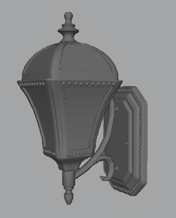
The sconce is essentially complete, but you don't necessarily have to be finished. You can continue to add details to the sconce and the bracket to decorate and detail it to your heart's desire. I took a bunch of spheres and arrayed them around the bracket as well as the sconce itself. These will catch the light in an interesting way and add visual interest (Figure 6.16).
With the high-resolution mesh complete, the low-resolution geometry can now be created. Just as with other projects in this book, the low-resolution mesh will receive the details from the high-resolution mesh through baking normal map details. You can create the low-resolution geometry in many ways. I find it easiest to simply duplicate the high-resolution geometry and remove the unnecessary polygons to get the low-resolution geometry that I want, but this method isn't always possible if the geometry is too complex.
First, select your entire high-resolution wall sconce and apply a new material by right-clicking and choosing Assign New Material → Lambert from the marking menu that opens.
The attributes of the new material should open. Lower the Color slider, making the mesh a dark hue.
Create a new layer in the Layer Bar. Double-click to open its properties and rename the layer Hi. With your wall sconce meshes selected, right-click the layer and choose Assign Selected.
Create another new layer and name it Lo. This will be the layer your low-resolution mesh will be assigned to.
Select the wall bracket (not any of the decorative details). Press Ctrl+D to duplicate it.
With the duplicate selected, right-click the Lo layer and assign the new mesh to it. With the mesh still selected, right-click in empty space and from the marking menu, choose Assign Existing Material → Lambert1. This will assign the existing default material to the duplicate wall bracket.
Next, select all of the duplicate bracket's vertices. Hold the W key and click to bring up the Move tool options. Hover your cursor over the Axis option. From the new options that appear, hover your cursor over Normal and release the left-mouse button.
This switches your Move tool to Normal Axis movement, which allows you to perform the next step.
With all the vertices selected and with the Move tool set to Normal Axis movement mode, click and drag on the move handle labeled N to slightly expand the mesh to encompass the original wall bracket geometry.
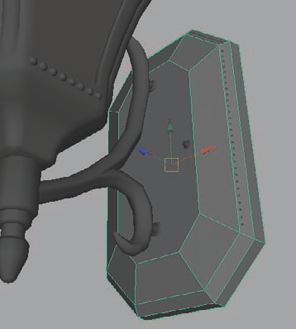
Now that the duplicate mesh encloses the original, you can begin to remove unnecessary geometry to lower the density of its polycount. The goal is to remove geometry that will not affect the duplicate's ability to continue to encase the original high-resolution mesh.
In Figure 6.17, you can see that my low-resolution wall bracket, although very low in polygonal density, is still able to encompass the entire high-resolution mesh. (This is hinted at by the bits barely poking through in the upper-right side. Don't worry, that won't affect the quality of the normal map that you'll eventually bake.)
The next piece of geometry you can simplify is the bottom decorative element below the sconce's light. Select it, duplicate and expand it just as you did with the wall bracket in the previous steps, and remove edge loops that are unnecessary for the shape.
For the looping, vine-like pieces that connect the sconce to the bracket, you'll follow the same process. Duplicate and expand both pieces. Remove edge loops that aren't necessary to keep the mesh surrounding the high-resolution geometry.
Once you have the two shapes, select them both and select Mesh → Booleans → Union. This will combine the two meshes together while deleting the geometry that intersected them. This will leave behind some ugly geometry (Figure 6.18).
Clean the geometry here so that it flows better between the two shapes and still encapsulates the original high-resolution meshes. Using Snap To Point and Merge, you can merge the extraneous points together to form the cleaner lines necessary for the part.

You can continue this process with the rest of the geometry, creating a low-resolution version of the sconce. Once you have the low-resolution mesh completed (Figure 6.19), you can start the UV process.
For UV mapping the sconce, you'll find it easier to stack UV shells of identical parts of the sconce. For instance, you can stack each of the four sides of the sconce on top of each other so that each side uses the same texture space. This will save space on your texture and allow for more detail. You can do this for the four sides of the dome on top of the sconce as well. It's best to choose a forward-facing side so as to limit the amount of influence the other surfaces of the object will have on the resulting texture bakes.

As always, keep in mind the size of the item in relation to the scale of its UV shell in the UV Texture Editor (found under the Window menu). If the object is tiny, its UV shell should be equally small in relation to the rest of the UV shells in the texture. There are exceptions, however. The main detail of an object—that is, the main part of the object that people will focus their attention on—could have a slightly larger scale attributed to its UVs. This is the same sort of method used in character texturing, where the character's face and eyes are given a larger amount of UV space, since that is where most people will focus their attention.
Just as focused parts have larger UV space, parts that are completely out of focus, such as the bottom of shoes, the interior of a character's mouth, or (in this case) the back of a wall bracket, should have smaller UV space given.
Select the faces that make up three of the four sides of your low-resolution sconce. Delete them. With the remaining geometry (the side, top, and bottom), UV map them normally.
Once your UVs are laid out for the remainder of the sconce, duplicate the faces on the side of the geometry (you may want to extract the top and bottom faces first using the Mesh → Extract command) and rotate them around the sconce to fill in the empty space.
The four sides of the sconce will now share the same UV space. If you need to reposition the UV shells for the sconce, make certain you select the UV shells for all four sides, as it is easy to accidently move one side and not the others.
You won't combine the four sides together just yet. You will do so after the textures are baked in the next section. You can UV the squared dome shape on top of the sconce in the same manner, sharing UV space for all four sides. For the rest of the object, however, you can UV map them normally (Figure 6.20).

As with all game assets, the next stage is to bake the high-resolution details to the low-resolution mesh to create the ambient occlusion (AO) and normal map source files.
Select your low-resolution geometry, excluding the duplicated sides of the sconce that share UV space. You only want one side of the low-resolution sconce and dome meshes to be selected. (The same is true with any other meshes that share UV space.)
Switch to the Rendering menu set and choose Lighting/Shading → Transfer Maps. Since your low-resolution meshes were selected, they'll automatically be loaded in the Target Meshes section of the Transfer Maps dialog box.
Select all of your high-resolution meshes and click the Add Selected button under the Source Meshes section of the Transfer Maps dialog box. If you have a lot of high-resolution meshes, it may take a minute or so for them all to load.
Next, indicate which maps you want to bake. You'll want an ambient occlusion map and a normal map. Click the appropriate buttons under the Output Maps section to make them appear below.
In each map's given section, indicate a location to save the image as well as the file format. As always, you'll choose Targa (tga).
Note
Targa is probably the most common image format used in games, but occasionally, other file formats are used, such as DDS and BMP formats. Consult your supervisor for details regarding the map types used for your project.
Below, in the Common Output sections, you can specify a file resolution. For the previous projects in this book, you've generally used a relatively large resolution, such as 1024×1024. This is fine for larger objects (like the dune buggy or building), but for small items, you generally want a smaller resolution.
For this project, choose 512×512 for both the Maya Common Output and Mental Ray Common Output settings.
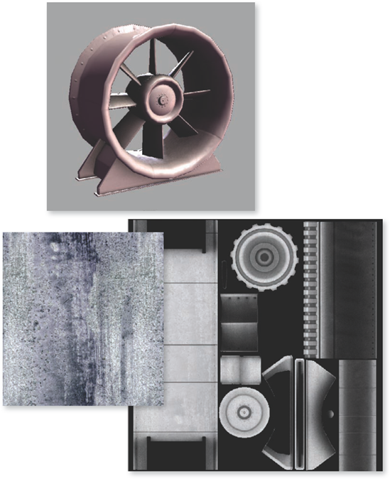
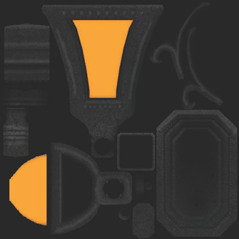
Once your settings are ready, click the Bake button and wait for Maya to finish generating the texture sources. You can see how mine turned out in Figure 6.21.
Note
At this point, you can combine and merge the separate sides of the sconce to make one single mesh. You can also continue to lower the geometry resolution of the low-resolution mesh even further, if you want; however, be careful not to affect the UV shell boundary geometry, or you may see your texture stretch badly.

Using your generated texture sources, you can create the final textures in Photoshop. For this project, you'll be making the usual diffuse, normal, and specular maps. In addition, you'll also create an emissive map (or "glow" map) to control the sconce's glow effect.
First, start Photoshop and open your baked AO texture. Double-click it and click OK on the dialog box that opens to change the image from a locked background to an editable layer. You can rename this layer
AO.Click the New Layer button (at the bottom of the Layer palette). Drag the new layer below the AO layer. Click the Foreground swatch on the left side of the interface and choose a dark color. Fill the empty layer with this color (Alt+Delete) and rename it
BaseColor.Select the AO layer and change its Blending Mode from Normal to Multiply. You should get something like Figure 6.22.
To help in the texture creation process, you can create a UV snapshot. The UV snapshot will produce an image of your UV layout that you can bring into Photoshop to use as a guide.
Back in Maya, select all of your low-resolution sconce meshes. Open the UV Texture Editor window and choose Polygons → UV Snapshot.
In the UV Snapshot dialog box, choose the 512 for Size X and Y, Targa for the Image Format, and choose a save location and name (such as
UV.tga) for the File Name setting.Return to Photoshop, and open the UV.tga file you just created. Drag and drop it into your texture's Photoshop file and drag its layer to the top of the layer palette's stack. Set its Blending Mode to Screen and lower its Opacity down to something like 20 percent. Rename this layer
UV.You can toggle this layer on and off to get a guide for your mesh's UV layout that is helpful for knowing where exactly a texture detail will show up on the final mesh.
Note
Make certain to hide the UV layer when saving your textures. Otherwise, your model will have wireframe lines all over it!
Create a new layer above the BaseColor layer. Name it
Glow. Use the Polygonal Lasso selection tool to select the area that will be glowing on your sconce. Remember to have the UV layer visible to help you make your selection accurately (Figure 6.23).Choose a yellow-orange color and, with the Glow layer active, fill in the selection.
If you're using my provided texture, position it on the image so that it covers all of it and change its Blending Mode to Color Dodge. This causes the metal detail to soften enough to look like it has had relatively mild weathering. Rename this layer
Metal.Above the Glow layer, create a Hue/Saturation adjustment layer (by clicking the Create New Fill or Adjustment Layer button at the bottom of the Layer palette). Increase its Lightness setting slightly—to about 8. Then click OK.
Select the masking swatch next to the adjustment layer's thumbnail icon and fill it with black (or simply invert the white color with the Ctrl+I shortcut command).
With a white brush and with the adjustment layer's mask still selected, paint over the raised portions of the sconce, increasing their brightness slightly (Figure 6.24).
Create another Hue/Saturation adjustment layer, this time decreasing the Lightness setting to about −35. Fill its mask with black and with a white brush, paint in the low areas of the texture with shadow.
This will be your diffuse texture! Save it as
Sconce_Diffuse.tga, and save the Photoshop file as well.


With the diffuse texture completed, now start the specular texture. We want the specular texture to be subtle, but not so subtle as to make no difference.
First, why don't you get a little organized? Select all of your current layers (except the UV layer) and select Layer → New → New Group From Layers. Name the new group Diffuse and click OK. Your diffuse texture layers will all go into their own group folder.
Select the Metal layer and duplicate it by dragging it to the New Layer button. Drag the duplicated layer out of the Diffuse folder and below the UV layer.
Ctrl+left-click the Glow layer to load it as a selection. With the duplicate Metal layer still selected, fill the selection with black. Change the duplicate Metal layer's Blending Mode to Normal and rename it
Metal_Spec. If you like, you can make a new group folder for this layer called Specular. Save this as your specular texture and call itSconce_Specular.tga(Figure 6.25).The reason you filled in the glowing area with black is so that there won't be a specular highlight visible within where the light should just be glowing brightly.

The normal map that you generated is actually suitable just as it is. So, all that's left is the new emissive texture! The emissive texture will indicate where on the model it should glow and with what color.
Select the Glow layer and duplicate it by dragging it to the New Layer button. Drag this new layer out of the Diffuse folder and place it above the Specular folder (not in it!). Rename it
Glow_Em.Create a new layer and place it below the Glow_Em layer. Fill it with black.
This is actually all you really need to create an emissive texture. However, you can add a lot of interest to the emissive texture by paying attention to how the glow of the light should actually work.
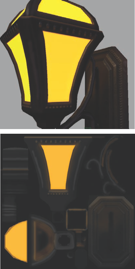
Create a new layer and place it above the Glow_Em layer. Hide the black layer that is below it and hide the Specular folder. You should be able to see the diffuse texture beneath the visible emissive layers. Rename your new layer
Glow_Falloff.With the same yellow-orange color as the glow, start painting around the sconce where the light of the glow should hit it. You would see it on each of the decorative spheres surrounding the sconce and wall bracket, as well as on the arm of the support frame.
Also pay attention to where the light of the glow would not cast, such as the shadow the support arm would cast onto the wall bracket. Continue to think logically about where the light would cast and paint in those details.
Lower the Glow_Falloff layer's Opacity down to around 25%. It should look something like Figure 6.26.
Once you're happy with how the glow looks, unhide the black layer separating the emissive and diffuse layers and save the result as
Sconce_Glow.tga.With the falloff details of the emissive texture included, you can create a lot more believability.
With this project I hope you were able to see that, even with a small, seemingly insignificant prop like a wall sconce, you can create a lot of detail and get a lot of added atmosphere for any environment. Another element that adds depth to an environment is movement. You'll explore this concept in the next chapter.