
7 International standards for short-circuit analysis in ac power systems
7.1 General
Guidelines and standards for short-circuit analysis have been developed in some countries. These standards generally aim at producing consistency and repeatability of conservative results or results that are sufficiently accurate for their intended purpose. Three very popular and widely used approaches are the International Electro-technical Commission (IEC) 60909–0:2001 Standard, the American Institute for Electrical and Electronics Engineers (IEEE) C37.010:1999 Standard and the UK Engineering Recommendation ER G7/4 procedure. In this chapter, we give a brief introduction to the three approaches.
7.2 International Electro-technical Commission 60909–0 Standard
7.2.1 Background
In 1988, the International Electro-technical Commission published IEC Standard IEC 60909 entitled ‘Short-Circuit Current Calculation in Three-Phase AC Systems’. This was derived from the German Verband Deutscher Electrotechniker (VDE) 0102 Standard. The IEC Standard was subsequently updated in 2001 and is the only international standard recommending methods for calculating short-circuit currents in three-phase ac power systems. Its aim, when conceived, was to present a practical and concise procedure, which, if necessary, can be used to carry out hand calculations and which leads to conservative results with sufficient accuracy. However, non-conservative results were subsequently identified in particular applications and this objective was revised in the 2001 update to ‘leading to results which are generally of acceptable accuracy’. Other methods, such as the superposition or ac method covered in Section 6.3.3, are not excluded if they give results of at least the same precision.
The Standard is applicable in low voltage and high voltage systems up to 550 kV nominal voltages and a nominal frequency of 50 or 60 Hz. The Standard deals with the calculation of maximum and minimum short-circuit currents and distinguishes between short circuits with and without ac current component decay corresponding to short circuits that are near to and far from generators.
7.2.2 Analysis technique and voltage source at the short-circuit location
The basis of the IEC 60909–0 Standard is the calculation of the initial symmetrical rms short-circuit current, ![]() , for any fault type by a method which is based on the use of an equivalent voltage source at the fault location such as the passive method covered in Section 6.3.2. The magnitude of this voltage source is equal to
, for any fault type by a method which is based on the use of an equivalent voltage source at the fault location such as the passive method covered in Section 6.3.2. The magnitude of this voltage source is equal to ![]() where Un is the nominal system phase-to-phase voltage and c is the voltage factor. The voltage factor is intended to give a worst-case condition and is assumed to account for the variations in loadflow conditions, voltage levels between different locations and with time, transformer off-nominal tap ratios and internal subtransient voltage sources of generators and motors. Table 7.1 shows the recommended value of the c factor.
where Un is the nominal system phase-to-phase voltage and c is the voltage factor. The voltage factor is intended to give a worst-case condition and is assumed to account for the variations in loadflow conditions, voltage levels between different locations and with time, transformer off-nominal tap ratios and internal subtransient voltage sources of generators and motors. Table 7.1 shows the recommended value of the c factor.
Table 7.1 Voltage factor c (IEC 60909–0)
| Voltage factor c for the calculation of | ||
|---|---|---|
| Nominal system phase-to-phase voltage Un | Maximum short-circuit currents (cmax) | Minimum short-circuit currents (cmin) |
| LV (100 V up to 1000 V) | ||
| Upper voltage tolerance +6% | 1.05 | 0.95 |
| Upper voltage tolerance +10% | 1.1 | 0.95 |
| MV and HV (>1 kV up to 550 kV) | 1.1 | 1 |
The calculations are based on the use of rated nominal impedances and neglecting capacitances and passive loads, except in the zero phase sequence (ZPS) networks in systems with isolated neutrals or resonant earth. The fault arc resistance is also neglected. The calculation method ignores the initial prefault system loading and operating conditions and is essentially a fixed impedance passive analysis method as described in Chapter 6. In calculating the maximum short-circuit currents, the resistances of lines and cables are calculated at 20°C whereas for minimum short-circuit current, higher conductor operating temperatures are used. A number of correction factors and scaling factors are used in order to satisfy acceptable accuracy whilst maintaining simplicity. In addition to the voltage factor c, the following factors are used:
(a) Factor KT for the correction of the impedance of network transformers.
(b) Factors KG; KS; KG, S; KT,S; KSO; GG,SO and KT,SO for the correction of the impedance of generator and combined generator-transformer units.
(c) Factor κ for the calculation of the peak make current.
(d) Factor μ for the calculation of symmetrical short-circuit breaking current.
(e) Factor λ for the calculation of symmetrical steady state short-circuit current.
(f) Factor μq for the calculation of the symmetrical breaking current of asynchronous motors.
IEC 60909 provides three methods for the calculation of the equivalent system X/R ratio at the fault point used in the calculation of the peak make current as well as the dc break current component at the minimum time delay tmin. IEC 60909–0 defines tmin as the shortest time from the instant of short circuit to contact separation of the first pole to open of the switching device. This is taken as the sum of the minimum relay protection time and minimum circuit-breaker operating time. In calculating the initial symmetrical short-circuit current, ![]() , for a far from generator short circuit, the positive phase sequence (PPS) and negative phase sequence (NPS) generator impedances are assumed equal.
, for a far from generator short circuit, the positive phase sequence (PPS) and negative phase sequence (NPS) generator impedances are assumed equal.
7.2.3 Impedance correction factors
Network transformers (factor KT)
Impedance correction factors are applied to the nominal rated impedance values of two-winding and three-winding network transformers. The correction factor covers transformers with and without on-load tap-changers if the transformer’s voltage ratio is different from the ratio of the base voltages of the network. The corrected PPS impedance is given by
and the correction factor KT is given by
where ZT = RT + jXT is the uncorrected rated transformer PPS impedance in Ω and xT is the rated transformer PPS reactance in pu. This correction factor is also applied to the transformer’s NPS and ZPS impedances. For three-winding transformers, the correction factor is applied to the three reactances between windings. For example, if the three windings are denoted A, B and C and the pu reactance between windings A and B with C open is considered, the correction factor is given by
and similarly for the two other windings.
No correction is applied to the star winding neutral earthing impedance, where present. Similarly, this correction factor is not applied to generator step-up transformers.
Directly connected synchronous generators and compensators (factor KG)
Where the short-circuit location is on a low or medium voltage network directly fed from generators without step-up transformers, such as in industrial power systems, a correction factor is applied to the PPS subtransient impedance of the generators. This correction is introduced to compensate for the use of the equivalent voltage source ![]() instead of the subtransient voltage E″ behind subtransient reactance calculated at rated operation. The corrected PPS subtransient impedance is given by
instead of the subtransient voltage E″ behind subtransient reactance calculated at rated operation. The corrected PPS subtransient impedance is given by
where the correction factor KG is given by
where ![]() is the uncorrected generator subtransient impedance, UrG is the rated phase-phase voltage of the generator, ϕrG is the phase angle between
is the uncorrected generator subtransient impedance, UrG is the rated phase-phase voltage of the generator, ϕrG is the phase angle between ![]() and the rated current IrG and
and the rated current IrG and ![]() is the generator subtransient reactance in pu. To calculate the peak make current using the factor κ (this is covered in Section 7.2.5), a fictitious generator resistance RGf is used such that:
is the generator subtransient reactance in pu. To calculate the peak make current using the factor κ (this is covered in Section 7.2.5), a fictitious generator resistance RGf is used such that:
The correction factor KG is also applied to the NPS and ZPS generator impedances but not to the generator neutral earthing impedance, where present. If the terminal voltage of the generator is different from UrG by a factor pG, then UrG in Equation (7.3b) is replaced by UrG (+ pG). Synchronous motors equipped with voltage regulation equipment are treated as synchronous generators.
Power station units with and without on-load tap-changers (factors KS; KG,S; KT,S; and KSO; KG,SO; KT,SO)
A power station unit is defined as the combined generator and its step-up transformer is shown in Figure 7.1. Two cases are considered: the first where the step-up transformer is equipped with an on-load tap-changer and the second where it is not.

Step-up transformer with an on-load tap-changer (factors KS; KG,S and KT,S)
For a short-circuit fault on the high voltage side of the step-up transformer, i.e. at F1, the corrected impedance of the entire power station unit referred to the high voltage side of the step-up transformer is given by
 (7.4a)
and the correction factor KS is given by
 (7.4b)
where ZTHV is the uncorrected transformer’s impedance referred to the high voltage side, UNQ is the nominal system voltage at the power station unit connection point, xT is the transformer reactance in pu at nominal tap position and tr = UrTHV/UrTLV is the rated voltage ratio of the transformer. ![]() may be replaced with UnQUQ min if experience shows that the minimum operating voltage is such that UQ min > UnQ and the worst-case current is not required. UrG may be replaced with UrG(1 + pG) if the actual generator voltage is always higher than the rated value. In Equation (7.4b), the absolute value of (
may be replaced with UnQUQ min if experience shows that the minimum operating voltage is such that UQ min > UnQ and the worst-case current is not required. UrG may be replaced with UrG(1 + pG) if the actual generator voltage is always higher than the rated value. In Equation (7.4b), the absolute value of (![]() ) is taken.
) is taken.
For unbalanced short circuits, KS is also applied to the NPS and ZPS impedances of the power station unit provided overexcited generator operation is assumed. The correction is not applied to the transformer’s neutral impedance, if present. However, for underexcited generator operation, the application of KS may give non-conservative results in which case the superposition method may be used. In calculating the current contribution of the entire power station unit on the transformer’s high voltage side, it is not necessary to take into account the contribution of the motors within the auxiliary system.
When calculating the partial short-circuit currents from the generator and through the transformer for a fault between the generator and the transformer, i.e. at F2, the generator and transformer impedance correction factors are, respectively, given by
and
Step-up transformer without an on-load tap-changer (factors KSO; KG,SO and KT,SO)
For a short-circuit fault on the high voltage side of the step-up transformer, i.e. at F1, the corrected impedance of the entire power station unit referred to the high voltage side of the step-up transformer is given by
and the correction factor KSO is given by
1 ± pT is used if the transformer has off-load taps and one tap position is permanently used otherwise pT = 0. If the highest current is required, then 1 – pT is used.
For unbalanced short-circuit faults, KSO is also applied to the NPS and ZPS impedances of the power station unit but not to the transformer’s neutral earthing impedance, if present. In calculating the current contribution of the entire power station unit on the transformer’s high voltage side, it is not necessary to take into account the contribution of the motors within the auxiliary system.
When calculating the partial short-circuit currents from the generator and through the transformer for a fault between the generator and the transformer, i.e. at F2, the generator and transformer impedance correction factors are, respectively, given by
and
7.2.4 Asynchronous motors and static converter drives
Low voltage and medium voltage motors contribute to the initial symmetrical short-circuit current, the peak make current, the symmetrical breaking current and, for unbalanced faults, the steady state short-circuit current. The contribution of medium voltage motors is included in the calculation of maximum short-circuit currents. The contribution of low voltage motors in power station auxiliaries and industrial power systems, e.g., chemical plant, steel plant and pumping stations, etc., is taken into account.
Large numbers of low voltage motors, e.g. in industrial installations and power station auxiliaries, together with their connection cables, can be represented as an equivalent motor. The rated current of the equivalent motor ![]() is the sum of the rated currents of all motors. For asynchronous motors in low voltage supply systems directly connected to the fault location, i.e. without intervening transformers, the motor’s contribution to the initial symmetrical short-circuit current may be neglected if
is the sum of the rated currents of all motors. For asynchronous motors in low voltage supply systems directly connected to the fault location, i.e. without intervening transformers, the motor’s contribution to the initial symmetrical short-circuit current may be neglected if
where ![]() is the total initial symmetrical short-circuit current at the fault location calculated without the contribution of the motors. If ILR/IrM = 5 where ILR is the motor’s locked rotor current, and
is the total initial symmetrical short-circuit current at the fault location calculated without the contribution of the motors. If ILR/IrM = 5 where ILR is the motor’s locked rotor current, and ![]() where
where ![]() is the initial short-circuit current of the motor, Equation (7.8a) gives
is the initial short-circuit current of the motor, Equation (7.8a) gives
The short-circuit PPS, and NPS, motor impedance is calculated using
where SrM and UrM are the rated apparent power and rated voltage of the motor. With PrM/p being the motor’s rated active power per pair of poles, the recommended XM/RM ratios of the motor’s short-circuit impedance are given by:
XM/RM. = 10 for high voltage motors with PrM/p ≥ 1 MW.
XM/RM = 6.67 for high voltage motors with PrM/p < 1 MW.
X/R = 2.38 for low voltage motor groups with connection cables.
Low voltage and medium voltage motors feeding through two-winding transformers to the short-circuit location may be neglected if
 (7.9b)
where ∑iPrM is the sum of the rated powers of low voltage and medium voltage motors, ∑iSrT is the sum of the rated apparent powers of all parallel transformers feeding the motors and ![]() is the initial symmetrical short-circuit current at the fault location calculated without motors. The absolute value of the denominator should be used if it is negative.
is the initial symmetrical short-circuit current at the fault location calculated without motors. The absolute value of the denominator should be used if it is negative.
Reversible static converter drives are considered for three-phase short circuits if the rotational masses of the motors and the static equipment provide reverse transfer of energy for deceleration at the time of the short circuit. They are considered to contribute to the initial symmetrical short-circuit current ![]() and the peak make current but they do not contribute to the symmetrical short-circuit breaking current or the steady state short-circuit current. These drives are represented as an equivalent asynchronous motor with the equivalent PPS impedance as given in Equation (7.9a) with ILR/IrM = 3 and XM/RM = 10.
and the peak make current but they do not contribute to the symmetrical short-circuit breaking current or the steady state short-circuit current. These drives are represented as an equivalent asynchronous motor with the equivalent PPS impedance as given in Equation (7.9a) with ILR/IrM = 3 and XM/RM = 10.
In the calculation of minimum short-circuit currents, the contribution of asynchronous motors is neglected.
7.2.5 Calculated short-circuit currents
Calculation of peak make current
From the initial rms symmetrical current ![]() , the peak make current for a single radial circuit is calculated using a peak factor κ and is given by
, the peak make current for a single radial circuit is calculated using a peak factor κ and is given by
where
and (X/R) is the system X/R ratio at the fault point calculated using generator fictitious resistance RGf as described in Section 7.2.3. The variation of κ with the X/R ratio is shown in Figure 7.2.

For parallel independent radial circuits, the total peak make current is the sum of the individual make currents of each radial circuit. For meshed systems, Equation (7.10a) is also used but Equation (7.10b) changes to
where (X/R)i is calculated in accordance with one of the following three methods:
Method A: Uniform X/R ratio
κ is calculated using the largest X/R ratio of all the network branches that feed partial short-circuit current into the fault location. This method can lead to significant errors.
Method B: Equivalent X/R ratio at the fault point
The X/R ratio at the fault point is calculated from the Thévenin’s impedance obtained by network reduction of complex impedances. A safety factor of 1.15 is used to compensate for the underestimate in the dc current caused by the different X/R ratios of network branches and sources, i.e.
The factor 1.15 κ should not exceed 1.8 and 2 in low voltage and high voltage systems, respectively. The 1.15 safety factor is not applied if the smallest X/R ratio in the network is greater than or equal to 3.33.
Method C: Equivalent frequency fc
Initially, the magnitude of network reactances are scaled from their power frequency f values to a reduced frequency fc then the Thévenin’s impedance at the fault point is calculated. If the calculated PPS and ZPS impedances at fc at the fault point are ![]() and
and ![]() the X/R ratio at the fault point is calculated from
the X/R ratio at the fault point is calculated from
 (7.13)
where f is nominal system frequency (50 or 60 Hz) and fc/f = 0.4. This gives the equivalent frequency fc = 20 Hz for f = 50 Hz and f = 24 Hz for f = 60 Hz. Equal PPS and NPS impedances are assumed. Similar equations can be derived for other fault types.
Calculation of dc current component
The maximum dc component of the short-circuit current is calculated using
where f is power frequency and (X/R) is the break X/R ratio calculated using Method C equivalent frequency depending on the minimum time fmin from the instant of fault. In calculating (X/R)b, the actual resistance of generators, RG, is used. The equivalent frequency fc to be used in calculating ZC is determined as shown in Table 7.2.

Calculation of rms symmetrical breaking current
For a near to generator three-phase short-circuit fault, consider first either a singly fed short circuit or a non-meshed network consisting of parallel independent short-circuit sources. In the case of two sources namely a synchronous generator and an asynchronous motor, the symmetrical short-circuit breaking current is given by
where
![]() and
and ![]() are the synchronous generator and asynchronous motor initial symmetrical short-circuit current contributions measured at their terminals. Denoting IrG and IrM as the generator and motor rated currents, the multiplying factors μ and q are given by
are the synchronous generator and asynchronous motor initial symmetrical short-circuit current contributions measured at their terminals. Denoting IrG and IrM as the generator and motor rated currents, the multiplying factors μ and q are given by
 (7.16)
For asynchronous motors, ![]() in Equation (7.16) is replaced with
in Equation (7.16) is replaced with ![]() . and
. and
 (7.17)
where PrM and p are the motor rated power in MW and number of pole pairs. The maximum value for q is unity. Equations (7.16) and (7.17) are plotted in Figures 7.3 and 7.4, respectively. Equation (7.16) for μ applies for synchronous generators employing rotating or static exciters provided, for the latter, that tmin < 250 ms and the maximum excitation voltage is < 1.6 pu of the rated value. μ is set equal to unity if the excitation system is unknown.

Figure 7.3 IEC 60909 factor μ used for calculation of short-circuit breaking current from synchronous generators

Figure 7.4 IEC 60909 factor q used with factor μ for calculation of short-circuit breaking current from asynchronous motors
For a far from generator three-phase short circuit, i.e. ![]() ≤ 2, or for unbalanced short circuits, μ = 1 and
≤ 2, or for unbalanced short circuits, μ = 1 and ![]() . Similarly, for far from motor three-phase short circuit or for unbalanced short circuits μq = 1 and
. Similarly, for far from motor three-phase short circuit or for unbalanced short circuits μq = 1 and ![]() .
.
For meshed networks, the approximation ![]() can be used. Alternatively, for improved accuracy, the decay in short-circuit currents from synchronous machines and asynchronous motors can be estimated from the partial step changes in voltage at the connection locations of the machines due to the fault and the following equation can be used:
can be used. Alternatively, for improved accuracy, the decay in short-circuit currents from synchronous machines and asynchronous motors can be estimated from the partial step changes in voltage at the connection locations of the machines due to the fault and the following equation can be used:
 (7.18a)
are the voltage drops at the terminals of the synchronous machine (i) and the asynchronous motor (j). ![]() is the corrected subtransient reactance of synchronous machine (i), i.e.
is the corrected subtransient reactance of synchronous machine (i), i.e. ![]() with Kv = KG, KS or KSO as appropriate and
with Kv = KG, KS or KSO as appropriate and ![]() is asynchronous motor j subtransient or transient reactance.
is asynchronous motor j subtransient or transient reactance. ![]() and
and ![]() are the initial symmetrical current contributions from synchronous machine (i) and asynchronous motor (j) as measured at their terminals. For a far from motor short circuit, μj = 1 and 1 – μjqj = 0 irrespective of the value of qj.
are the initial symmetrical current contributions from synchronous machine (i) and asynchronous motor (j) as measured at their terminals. For a far from motor short circuit, μj = 1 and 1 – μjqj = 0 irrespective of the value of qj.
Calculation of rms symmetrical steady state current
IEC 60909–0 recognises that the calculation of the steady state current Ik is less accurate than the calculation of ![]() because it depends on factors such as the generator initial operating point, machine saturation, excitation system characteristics and automatic voltage regulator action, etc. Worst-case assumptions are made to calculate maximum and minimum steady state short-circuit currents using factors expressed in terms of the generator rated current. For a single-fed near to generator three-phase short circuit, the maximum and minimum steady state short-circuit current is given by
because it depends on factors such as the generator initial operating point, machine saturation, excitation system characteristics and automatic voltage regulator action, etc. Worst-case assumptions are made to calculate maximum and minimum steady state short-circuit currents using factors expressed in terms of the generator rated current. For a single-fed near to generator three-phase short circuit, the maximum and minimum steady state short-circuit current is given by
λmax is a factor that is dependent on the saturated direct axis synchronous reactance and for turbo-generators and salient-pole generators is obtained from IEC 60909–0 Figures 18(a and b) and 19(a and b), respectively. For turbo-generators, these figures apply for maximum excitation voltages of 1.3 and 1.6 pu whereas for salient-pole generators, they apply for maximum excitation voltages of 1.6 and 2 pu. The voltage factor c = cmax is used. λm;n is calculated under constant no-load excitation, i.e. without voltage regulator action and the c factor used is c = cmin.
For meshed networks, ![]() and
and ![]() and similarly for unbalanced short-circuit faults.
and similarly for unbalanced short-circuit faults.
7.2.6 Example
Example 7.1
In Figure 6.10, the dc current component was calculated using an accurate time domain solution, IEC 60909 Method B and IEEE C37.010 Method. Repeat the calculation using IEC 60909 Method C and compare the result against the accurate time domain solution assuming a 50 Hz power system.
The equivalent frequency used to calculate the peak make factor is 20 Hz and together with the equivalent frequencies shown in Table 7.2, the equivalent X/R ratios and corresponding time constants of the three parallel branches are calculated using Equation (7.13). The results are summarised in Table 7.3 and the dc current comparison is shown in Figure 7.5.


Figure 7.5 IEC 60909 dc current component of three parallel independent sources calculated using IEC Methods B and C and accurate time domain solution
The equivalent frequency Method C is clearly far superior to Method B because it calculates new and higher X/R ratios and hence dc time constants as time elapses from the onset of the short-circuit fault. This process counteracts the increasing underestimate with time of Method B. In practice, it is found that Method C ensures that the degree of error is kept to a minimum.
7.3 UK Engineering Recommendation ER G7/4
7.3.1 Background
Following the publication of IEC 60909 in 1988, the UK electricity supply industry convened a group of power system engineers from across the industry to consider the application of IEC 60909 or a more appropriate alternative. As a result, Engineering Recommendation ER G7/4 ‘Procedure to Meet the Requirements of IEC 60909 for the Calculation of Short-Circuit Currents in Three-Phase AC Power Systems’ was published in 1992. At that time, although most companies in the UK used computer methods for the calculation of short-circuit currents, a variety of approaches were used for both the modelling of power system elements and the techniques used in the calculation of short-circuit currents. As a result, different short-circuit current results would be obtained for the same power system characteristics.
UK ER G7/4 is a procedure that sets out ‘good industry practice’ and applies for the calculation of short-circuit currents used in the assessment of circuit-breaker make and break duties in ac power systems having a nominal voltage range of 3 80 V to 400 kV. It is also applicable for currents used in the calculation of protection relay settings and mechanical forces on conductors and busbars.
7.3.2 Representation of machines and passive load
Synchronous machines
Synchronous machines are represented by a voltage source behind an impedance model where the PPS reactance is time dependent and is given by
The time constants are affected by the external network between the machine and the point of fault, as discussed in Chapter 6. Where the machines are connected to the faulted network by step-up transformers having comparable reactances to the machine subtransient reactances, unsaturated subtransient and transient reactances are used. However, saturated reactances are used where the machines are directly connected to the faulted system. For extended fault clearance times, the effect of excitation control systems, and in particular those that have high speed response, may need to be considered.
Asynchronous machines
Asynchronous machines or groups of such machines are represented by a voltage source behind an impedance model where, for a single-cage or single-winding rotor, the time-dependent PPS reactance is given by
where X′ and T′ are calculated from the machine parameters or tests as discussed in Chapter 5. Like synchronous machines, the time constant is modified by the external network impedance. Where neither the internal parameters of the machines nor its starting characteristics are known, the IEC 60909–0 approach of using the ratio of locked rotor current to rated current shown in Equation (7.9a) can be used to calculate the initial PPS impedance. If ac current decrement cannot be directly represented, the asynchronous machine’s current adjustment factor (μq) of IEC 60909 of Equation (7.15b) is used to calculate the PPS reactance corresponding to any elapsed time t after the instant of fault as follows:
X/R ratios for induction motors and static converter drives are considered as per IEC 60909–0 and is given in Section 7.2.4. The NPS impedance is assumed equal to the initial motor PPS impedance.
Small induction motors forming part of the general power system load
Numerous small induction motors that form part of the general load in the power system and hence are not individually identifiable are represented as an equivalent motor. The initial PPS impedance and time constant of the equivalent motor should be obtained by measurement. In the absence of measured data, indicative empirical estimates are suggested. For calculating the initial three-phase rms short-circuit current contribution at a 33 kV bulk supply substation busbar from induction motors in the general load supplied from that busbar the induction motor contribution is represented as follows:
(a) 1 MVA of short-circuit infeed per MVA of aggregate substation winter demand where the load is connected at low voltage, i.e. ≤ 1 kV
(b) 2.6 MVA of short-circuit infeed per MVA of aggregate substation winter demand where the load is connected at medium voltage, i.e. > 1 kV
These short-circuit infeeds relate to a complete loss of supply voltage to the motors.
The time variation of the PPS reactance of the equivalent motor is given by Equation (7.21) and the ac time constant is taken as T′ = 40 ms. It is therefore assumed that the contribution to a three-phase short circuit from motors in the general load decays to a negligible value at around 120 ms. The effective X/R ratio of the equivalent motor at the 33 kV busbar is taken equal to 2.76.
Passive loads
Both the real and reactive power components of passive loads are represented in the analysis. In particular, ER G7/4 recognises that the reactive load may have an appreciable effect on short-circuit currents because of its effect on transformer tap positions and rotating plant internal voltages.
7.3.3 Analysis technique
IEC 60909 describes methods for the hand calculation of short-circuit currents that lead to results that are generally of acceptable accuracy for their intended purpose. However, other methods are not excluded provided they give results of at least the same precision. ER G/74 is essentially a computer-based short-circuit current calculation procedure that uses the superposition method and can be used as an alternative to IEC 60909 where higher precision is required. ER G7/4 is based on the following key principles:
(a) Credible prefault power system operating conditions giving rise to maximum short-circuit currents are first established.
(b) Prefault ac loadflow studies are carried out to determine the network voltage profile, internal voltages of generators and motors and transformer tap positions.
(c) The short-circuit contributions of all rotating plant are included. In addition to individually identifiable rotating plant, the aggregate effect of numerous small motors forming part of the general load in the power supply system are included using a suitable equivalent.
The loadflow results and the current changes due to the short circuit are combined using the superposition theorem as described in Chapter 6. A search is carried out for the worst-case prefault operating condition that leads to the maximum short-circuit current.
The above procedure is intended for use where calculations of improved accuracy are required. However, a simplified procedure that does not use a loadflow study may also be used where maximum currents are well within the rating of plant and equipment. Such a procedure will still include the contributions of all rotating plant including induction machines.
ER G7/4 does not specify the analysis methods to be used in calculating the ac and dc components of short-circuit currents or their decrements. The user may choose to use suitable time-step simulations or fixed impedance techniques similar to those described in Chapter 6.
7.3.4 Calculated short-circuit currents
The short-circuit currents calculated by ER G7/4 are the short-circuit making and breaking currents. The magnitude of each of these currents consists of an rms ac current component and a dc current component. Although the initial value of the dc component depends on the point on the voltage waveform at which the fault occurs, maximum dc current offset is assumed.
Short-circuit making current
This is the peak asymmetric current or the maximum instantaneous value of the prospective short-circuit current. If the analysis method used does not allow the initial peak current to be directly calculated, IEC 60909 Equation (7.10) is used.
Short-circuit breaking current
The short-circuit breaking current allows for both ac and dc current decay. Both the ac and dc currents are calculated at a specified break time tb. The magnitude of the dc current component at t = tb, is given by
To determine the ability of a circuit-breaker to interrupt these component currents or a combination of them, reference should be made to the test data of the circuit-breaker and the standards on which the test data is based, e.g. BS 116:1952, ESI 41–10:1987 or IEC 62271–100 Standard.
X/R ratio for estimation of the magnitude of the dc current component
The system X/R ratio at the fault point is calculated and used to estimate the magnitude of the required dc current component where explicit calculation of the asymmetric initial peak and break currents cannot be made. If some network elements have X/R ratios below 3.3, as may be the case in low voltage networks, then a 1.15 safety factor is used in calculating the peak asymmetric currents unless the equivalent frequency Method C of IEC 60909 is used to calculate the X/R ratio. Since the time constants of the dc current decrements for three-phase and earth faults, e.g. single-phase to earth fault, are different, different X/R ratios will need to be evaluated. Where a conservative estimate is adequate, the initial peak current can be assumed to be equal to ![]() for low voltage networks (i.e. 1 kV or below) and
for low voltage networks (i.e. 1 kV or below) and ![]() for networks operating above 1 kV thereby obviating the need to calculate the X/R ratio.
for networks operating above 1 kV thereby obviating the need to calculate the X/R ratio.
7.3.5 Implementation of ER G7/4 in the UK
In this section, we briefly describe the implementation of ER G7/4 in computer analysis methods in England and Wales. The analysis is based on the fixed impedance technique where synchronous and induction machines are represented by a voltage source behind a fixed impedance. Essentially, two rms symmetrical short-circuit currents are calculated corresponding to two time instants. The first is the initial symmetrical rms short-circuit current, ![]() , corresponding to the instant of fault, and the second is the symmetrical rms short circuit after the subtransient contribution has decayed to a negligible value,
, corresponding to the instant of fault, and the second is the symmetrical rms short circuit after the subtransient contribution has decayed to a negligible value, ![]() . In order to calculate these two PPS currents, two PPS networks are created: a subtransient network and a transient network using machine subtransient and transient reactances, respectively. Corresponding to these two time instants, two system X/R ratios are calculated using IEC 60909 equivalent frequency Method C and these are denoted (X/R)i and (X/R)b where i and b represent initial and break, respectively. The peak make current is calculated as follows:
. In order to calculate these two PPS currents, two PPS networks are created: a subtransient network and a transient network using machine subtransient and transient reactances, respectively. Corresponding to these two time instants, two system X/R ratios are calculated using IEC 60909 equivalent frequency Method C and these are denoted (X/R)i and (X/R)b where i and b represent initial and break, respectively. The peak make current is calculated as follows:
The rms subtransient current component at the fault location is assumed to have a single effective subtransient time constant of 40 ms, i.e. it is assumed that all subtransient components from across the system have decayed to a negligible value by 120 ms. The break time tb is defined as the time from the instant of short-circuit fault to the time instant that corresponds to the peak of the major current loop just before current interruption at current zero. Thus, for a given break time tb in ms, the rms ac break current component is given by
An inherent assumption in Equation (7.25) is that the effect of even modern fast acting excitation control systems is negligible for tb < 120 ms. However, after this time, the reduction in fault current due to increasing machine reactance is offset by the action of excitation control systems through field voltage forcing and the short-circuit current is assumed to remain constant at ![]() .
.
The magnitude of the dc current component at the break time tb is calculated, assuming maximum offset, as follows:
Practical break times considered are those that correspond to the peaks of major asymmetrical current loops, i.e. approximately 30, 50, 70, 90 and 110 ms, etc. in the UK 50 Hz power system. If the amplitude of the peak asymmetric break current at t = tb is required, then this is calculated using Equations (7.25) and (7.26) as
Alternatively, if the rms asymmetric breaking current of the total asymmetric current is required, as may be the case for the old British Standard BS 116 and IEEE C37.010 Standard, then this is calculated using Equations (7.25) and (7.26) as
For balanced faults, subtransient and transient PPS system admittance matrices are formed. In addition, NPS and ZPS system admittance matrices are formed in the case of unbalanced faults. The formation of the NPS matrix allows machines to have a different NPS reactance from machine PPS reactance as well as the correct modelling of plant such as quadrature boosters and phase shifters. Passive loads shunt admittances are included in the PPS and NPS short-circuit current calculations but not in the ZPS networks where loads are separated from the bulk distribution system by one or more delta connected transformer windings.
The initial and break system X/R ratios are calculated using the equivalent frequency Method C of IEC 60909. In the UK 50 Hz power system, 20 Hz is used in the calculation of (X/R)i and an appropriate equivalent frequency is selected from Table 7.2, depending on the break time tb, in the calculation of (X/R)b.
In addition to the PPS system X/R ratio, NPS and ZPS system X/R ratios are also calculated depending on the unbalanced fault being studied. In the calculation of the PPS X/R ratio, all passive shunts, e.g. line shunt capacitances and load impedances, etc., are excluded. However, the calculated NPS and ZPS X/R ratios generally include the network shunt elements.
7.4 American IEEE C37.010 Standard
7.4.1 Background
The IEEE method for the calculation of system short-circuit currents is described in IEEE Standard C37.010:1999 which is a revision of C37.010:1979. The Standard is entitled IEEE Application Guide for AC High-Voltage Circuit Breakers Rated on a Symmetrical Current Basis. Prior to 1964, the applicable American National Standard Institute (ANSI) Standards were based on ‘Total Current Basis’ as opposed to ‘Symmetrical Current Basis’. The IEEE C37.010:1999 Standard is applicable to high voltage circuit-breakers above 1 kV for use in utility, industrial and commercial power systems operating at a nominal frequency of 60 Hz.
The IEEE C37.010 short-circuit calculation methodology was developed to provide conservative results for the determination of short-circuit duties and the sizing and selection of circuit-breaker ratings. The method is intended to provide a degree of accuracy that is within the practical limits of short-circuit calculation considering the accuracy of data that are usually available for such computations. The asymmetrical short-circuit current waveform is assumed to have maximum dc current offset. Other alternative methods, though not identified, are not excluded if they give results of at least the same precision. The Standard makes no distinction between radial or single-fed short circuits and those fed from meshed power systems. The Standard deals with the calculation of maximum short-circuit currents only and distinguishes between short circuits with significant and insignificant ac current component decay corresponding to short circuits that are local to or remote from generators, respectively.
Unlike IEC 60909 or ER G/74 which are short-circuit current calculation procedures only, the IEEE Standard is aimed at the sizing and selection of circuit-breakers. As a result, the IEEE short-circuit calculation methodology is included within a circuit-breaker application guide.
7.4.2 Representation of system and equipment
The IEEE Standard uses the concept of ‘local’ and ‘remote’ generation contribution to the short-circuit fault. If the external reactance between the generator terminals and the short-circuit location is such that XExternal > ![]() , the generator is considered to be remote. Otherwise, it is considered to be local. The IEEE Standard recommends neglecting the shunt impedances of static loads as well as the PPS line capacitance. The NPS and PPS reactances of rotating plant are assumed equal and similarly for the NPS and PPS resistances.
, the generator is considered to be remote. Otherwise, it is considered to be local. The IEEE Standard recommends neglecting the shunt impedances of static loads as well as the PPS line capacitance. The NPS and PPS reactances of rotating plant are assumed equal and similarly for the NPS and PPS resistances.
Two separate and different impedance networks are created; the first is the closing & latching (momentary) impedance network and the second is the interrupting impedance network. From the first network, the first cycle symmetrical current and the system X/R ratio are calculated and these are used to calculate the closing and latching current duty. From the interrupting impedance network, the symmetrical interrupting current and the system X/R ratio are calculated and these are used to calculate the asymmetrical interrupting current duty. The Standard recommends machine reactance adjustment factors, i.e. multipliers to account for ac current decay and these are generally different for the closing and latching duty, and interrupting duty calculations as shown in Table 7.4.
Table 7.4 Machine reactance adjustment factors to account for ac short-circuit current decay according to IEEE C37.010 Standard
| PPS reactances (pu) | ||
|---|---|---|
| Type of rotating machine | Closing and latching network | Interrupting network |
| All turbo-generators, all hydro-generators with damper windings and all condensers | ||
| Hydro-generators without damper windings | ||
| All synchronous motors | ||
| Induction motors | ||
| Above 1000 hp at 1800 rpm or less | ||
| Above 250 hp at 3600 rpm | ||
| From 50 to 1000 hp at 1800 rpm or less | ||
| From 50 to 250 hp at 3600 rpm |
Three-phase induction motors below 50 hp and all single-phase motors are neglected. ![]() and
and ![]() of synchronous machines are the rated voltage saturated values.
of synchronous machines are the rated voltage saturated values.
7.4.3 Analysis technique
General
IEEE C37.010 is a fixed impedance short-circuit calculation method. The initial generator and motor prefault loading conditions are not modelled nor are the explicit decay rates of individual generators and motors. The Standard recommends the use of a voltage source at the short-circuit location whose magnitude is equal to the highest typical prefault operating voltage E at the fault location.
The system X/R ratio at the fault point is calculated from separate X and R networks. The standard assumes that the reduction of separate X and R networks tends to correct for the multiple time constants and associated decay rates due to short-circuit currents passing through multiple paths to the fault location. In practical cases, the resultant error is on the conservative side.
Both a simplified E/X method and a more accurate, semi-rigorous, E/X method that accounts for ac and dc current decrements are described. Where the use of impedances is preferred to the use of reactances in the calculation of the magnitude of short-circuit current, the E/X calculation may be replaced with E/Z calculation.
E/X simplified method
The E/X simplified method calculates the symmetrical short-circuit current and is very simple to use. The ‘E’ represents the prefault voltage at the short-circuit location. The ‘X’ is the equivalent system reactance at the fault point calculated with the resistances of network elements set to zero and machine reactances set to their subtransient values. The equivalent reactance at the fault point is equal to Xp for three-phase short circuits and 2XP + XZ for single-phase to earth short circuits. The calculated short-circuit currents are thus E/XP for three-phase short circuits and 3E/(2XP + XZ) for single-phase short circuits. The Standard considers this simplified procedure to be sufficient provided that:
(a) The calculated three-phase short currents do not exceed 80% of the circuit-breaker symmetrical interrupting capability.
(b) The calculated single-phase to earth short-circuit currents do not exceed 70% of the circuit-breaker symmetrical interrupting capability for single-phase to earth short circuits.
Otherwise, the more accurate E/X procedure, described below, should be used.
E/X method with correction for ac and dc decrements
This more accurate procedure involves applying multiplying factors to the E/X calculated short-circuit results to account for ac and dc current decrements. The factors to be used depend on the calculated system X/R ratio seen at the fault point and on whether the fault is ‘local’ to or ‘remote’ from generation. The applicable factors are taken from three figures in the IEEE Standard namely ‘Figures 8, 9 and 10’. The curves of ‘Figures 8 and 9’ give the Kacdc factor that includes the effects of both ac and dc decrements and applies for ‘local’ three-phase and single-phase to earth short circuits. ‘Figure 8’ gives a maximum value of Kacdc of 1.25 which supports the 80% criterion used in the application of the E/X simplified method for three-phase faults. ‘Figure 9’ gives a maximum multiplying factor of Kacdc of 1.41 which supports the 70% criterion used in the application of the E/X simplified method for one-phase faults. ‘Figure 10’ gives the Kdc factor that includes the effect of dc decrement only and applies for ‘remote’ three-phase and single-phase short-circuit faults. These three figures also include multipliers for longer circuit-breaker contact parting times than the minimum. The corrected E/X short-circuit current result should not exceed the symmetrical interrupting capability of the circuit-breaker. A more accurate multiplying factor can be determined by using the ratio of remote generation contributions to total fault current known as the no ac decrement or NACD ratio. The new multiplying factor KInterpolated may be obtained by interpolation between Kacdc and Kdc using the NACD ratio as follows:
7.4.4 Calculated short-circuit currents
First cycle symmetrical current
This is the half cycle rms current and is calculated using the closing and latching impedance network and the appropriate machine reactances shown in Table 7.4.
Closing and latching current
The closing and latching current is equivalent to the half cycle peak current. If the first cycle symmetrical current including motor infeed is below the symmetrical current rating of the circuit-breaker and the system X/R ratio is less than 17 at 60 Hz, then no further calculations are required. If the system X/R ratio is greater than 17, the closing and latching current, expressed as a peak current, may be calculated using a peak factor similar to the IEC 60909–0 peak factor κ of Equation (7.10) as follows:
where the X/R ratio is calculated from the closing and latching impedance network.
If the value of the closing and latching current duty is calculated as a total rms value of the asymmetrical peak current, a simplified rule using a factor equal to 1.6 times first cycle symmetrical current, which assumes an X/R ratio of 25 at 1/2 cycle, may be used. Alternatively, the total rms value may be calculated using a more accurate multiplying factor of the rms symmetrical current based on the calculated X/R at the fault location as follows:
 (7.31)
Symmetrical interrupting current
This current is calculated using the interrupting impedance network and the appropriate machine reactances shown in Table 7.4.
Asymmetrical interrupting current
The asymmetrical interrupting current is calculated using the symmetrical interrupting current and an applicable multiplying factor which is a function of the circuit-breaker contact parting time and the system X/R ratio at the fault location. The factor is obtained from C37.010 ‘Figures 8, 9 and 10’ depending on whether the fault is fed by local or remote sources and the short-circuit type. The asymmetrical interrupting current duty is calculated as an rms value of an asymmetrical current.
Time-delayed 30 cycle (steady state) current
The time-delayed 30 cycle (steady state) short-circuit current applies when transient effects have completely decayed. In calculating this current, C37.010 recommends the use of a network that comprises only generators represented by either their transient reactance or a higher reactance that takes into account the ac component decay. The dc component is assumed to have decayed to zero.
7.5 Example calculations using IEC 60909, UK ER G7/4 and IEEE C37.010
Example 7.2
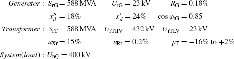
Consider the simple example network shown in Figure 7.6 to illustrate the maximum current quantities supplied by a power station unit for a three-phase short-circuit fault on the high voltage side of the transformer.
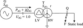
Figure 7.6 Example of a simple circuit for calculation of maximum short-circuit currents according to various standards
At node Q, the power station unit supplies a static impedance load, the load voltage magnitude is 380 kV and the generator is operating at rated active and reactive power output. The calculations are carried out in accordance with IEC 60909, UK ER G7/4 and IEEE C37.010. The turbo-generator and transformer data on their MVA rating are:
IEC 60909 calculation
The transformer impedance in Ω referred to the high voltage side is calculated as
The generator impedance in ω is calculated as
Using Equation (7.4b), the correction factor of the power station unit is given by
Using Equation (7.4a), the corrected impedance of the power station unit referred to the high voltage side is given by

The three-phase short-circuit current supplied by the power station unit is given by
Since UrG > 1 kV and rated apparent power SrG > 100 MVA, RGf = ![]() and RGf = 0.0081 ω. Thus, the corrected impedance of the power station unit referred to the high voltage side is given by
and RGf = 0.0081 ω. Thus, the corrected impedance of the power station unit referred to the high voltage side is given by

Therefore, XSf/RSf = 30. From Equation (7.10b), the peak current factor is given by κ = 1.02 + 0.98e-3/30 = 1.9067. Using Equation (7.10a), the peak current is given by ![]() .
.
To calculate the rms breaking current, we need to calculate the factor μ which depends on the minimum time tmin and the ratio ![]() . The rated current is given by
. The rated current is given by ![]() . The short-circuit current delivered by the generator at its terminals to the high voltage side fault is given by
. The short-circuit current delivered by the generator at its terminals to the high voltage side fault is given by ![]() . The required ratio is
. The required ratio is
Therefore, using Equation (7.16) and tmin = 50 ms, we have
The rms short-circuit breaking current is given by
The magnitude of the dc breaking current at tmin = 50 ms is calculated using Equation (7.14) and (X/R)b = 97.239/1.1197 = 86.84, thus
UK ER G7/4 calculation
The most realistic operating condition of the power station unit before the short circuit that maximises the short-circuit current is when the generator is producing rated power output and the magnitude of the high voltage is minimum. The rated generator power output in pu on rating is given by SrG = (0.85 + j0.526)pu. With a transformer on-load tap-changer, UrG =1.0 pu. The generator load current is calculated from ![]() and is given by IrG = (0.85 – j0.526)pu. Considering the voltage drop across the transformer rated impedance, we have
and is given by IrG = (0.85 – j0.526)pu. Considering the voltage drop across the transformer rated impedance, we have
The transformer tap ratio required to achieve a high voltage voltage of 0.95 pu is equal to t = 0.95/0.928 = 1.0237.
For a real network, the above prefault quantities are calculated using a computer-based ac loadflow study.
The subtransient and transient internal voltages of the generator are given by
The short-circuit subtransient current is calculated as
or
The short-circuit transient current is calculated as
or
The system initial and break X/R ratios at the fault point are calculated as follows:
The peak make short-circuit current is calculated using Equation (7.24)
The short-circuit rms break current at 50 ms break time is calculated using Equation (7.25) or
The magnitude of the dc break current at 50 ms break time is calculated using Equation (7.26) or
The peak asymmetric break current at 50 ms break time is calculated using Equation (7.27) or
The rms asymmetric break current at 50 ms break time is calculated using Equation (7.28)or
IEEE C37.010 calculation
The highest typical operating voltage on the transformer high voltage side is 1.03 pu. Using the subtransient reactance of the generator, the total subtransient reactance at the fault point is equal to 0.18 + 0.15 = 0.33 pu. The short-circuit current is given by
No further calculations are required if this current is smaller than 80% of the symmetrical interrupting capability of the circuit-breaker. Otherwise, the more accurate method is used.
E/X method with correction for ac and dc decrements
The first cycle rms current is calculated using the ‘closing and latching’ network and is given by
Using Equation (7.30), the closing and latching duty peak current is calculated as
This peak current duty must not exceed the corresponding breaker capability of 2.6 times the rated symmetrical short-circuit current. Alternatively, if the total rms current is required, this can be calculated using Equation (7.31) as follows:
For a 5-cycle breaker and a 3-cycle contact parting time, the multiplying factor for X/R = 86.84 is obtained from ‘Figure 8’ in IEEE C37.010 and is equal to 1.225. Therefore, the product 1.225 × 2.65 = 3.25 kA must not exceed the symmetrical interrupting capability of the circuit-breaker.
Example 7.3
The above example for IEEE C37.010 analysis is trivial. Therefore, consider the network shown in Figure 7.7 that provides a more realistic example of the IEEE C37.010 calculation method. All quantities shown in Figure 7.7 are in % on 100 MVA base and F is the short-circuit fault location. The circuit-breaker being considered is denoted as breaker A and is a 132 kV, 16 kA, 5-cycle breaker with a 3-cycle contact parting time.

Figure 7.7 Example of a simple system for the calculation of maximum short-circuit currents according to IEEE C37.010 Standard
Case 1: three-phase short-circuit fault
The reader may draw the PPS impedance network model of the system to help in the calculation of the Thévenin’s impedance at the fault point. The Thévenin’s equivalent PPS reactance (all resistances set to zero) and PPS resistance (all reactances set to zero) at the fault point are calculated as

and

The highest typical operating voltage at the circuit-breaker location is 1.03 pu. The first cycle symmetrical short-circuit current is equal to
The X/R ratio is given by 0.034/0.0016 = 21.25. Using Equation (7.30), the closing and latching duty peak current is calculated as follows:

This peak closing and latching duty is lower than the circuit-breaker peak current capability of 2.6 × 16 = 41.6 kA. Alternatively, if the rms value of the total asymmetric current is required, this can be calculated using Equation (7.31) as follows:

For this 5-cycle circuit-breaker with a 3-cycle contact parting time, the interrupting duty to be compared with the symmetrical interrupting capability of 16 kA and is equal to 1.0 × 13.25 = 13.25 kA where the multiplying factor of 1.0 is obtained from ‘Figure 8’ of IEEE C37.010 at X/R = 21.25.
Case 2: single-phase to earth short-circuit fault
Again, the reader may draw the ZPS impedance network model of the system. The Thévenin’s equivalent ZPS reactance (all resistances set to zero) and ZPS resistance (all reactances set to zero) at the fault point are calculated as

and
The first cycle symmetrical short-circuit current is equal to
Using Equation (7.30), the closing and latching duty peak current is calculated as
This peak closing and latching duty is lower than the circuit-breaker peak current capability of 2.6 × 16 = 41.6 kA. If the rms value of the total asymmetric current is required, this can be calculated using Equation (7.31) as
For this 5-cycle circuit-breaker with a 3-cycle contact parting time, the interrupting duty to be compared with the symmetrical interrupting capability of 16 kA is equal to 1.06 × 14 = 14.84 kA where the multiplying factor of 1.06 is obtained from ‘Figure 9’ of IEEE C37.010 at X/R = 23.6.
7.6 IEC 62271–100–2001 and IEEE C37.04–1999 circuit-breaker standards
7.6.1 Short-circuit ratings
Breaking or interrupting rating
IEC 62271–100 defines a rated short-circuit breaking current in kA and this is characterised by two values; the rms value of its ac component and the percentage dc component. Standard values of the ac component are selected from the R1O series 6.3, 8, 10, 12.5, 16, 20, 25, 31.5, 40, 50, 63, 80 and 100 kA.
The IEEE Standard defines a symmetrical interrupting capability equal to rated short-circuit current × K where K = 1 for most modern circuit-breakers. For some older circuit-breakers, K = rated maximum voltage/operating voltage except that for single-phase to earth faults, the symmetrical interrupting capability is 15% higher. The IEEE rated short-circuit current in amperes is equivalent to the IEC rms ac component of the rated short-circuit breaking current.
dc current rating
In both IEC and IEEE Standards, the value of the percentage dc component can be determined from an envelope that consists of a single decaying exponential having a time constant Tdc. The percentage value of the dc component (%dc) in per cent of the peak ac current component or peak symmetrical interrupting capability is given by
where
and (Tr + Tcb) is the circuit-breaker contact parting time measured from the fault instant. Tcb, is the minimum opening time of the circuit-breaker and Tr is the protection relay time and is equal to half cycle of power frequency (10 ms at 50 Hz and 8.33 ms at 60 Hz). Tr is equal to zero for self-tripping circuit-breakers.
If the rms component of the short-circuit breaking current or the symmetrical current component is denoted ISym in kA, the dc current component in kA is given by
Both IEC and IEEE specify a standard dc time constant Tdc = 45 ms. In addition, IEC provides special case time constants related to the rated voltage of the circuit-breaker. These recognise the higher time constants that may be encountered at locations close to generating stations, transformer or series reactor fed faults and extra high voltage transmission lines, etc. The special case time constants are:
(a) Tdc = 120 ms for rated voltages up to and including 52 kV.
(b) Tdc = 60 ms for rated voltages from 72.5 kV up to and including 420 kV.
The dc current envelope rating is shown in Figure 7.8.
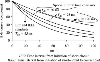
Figure 7.8 Percentage dc current component for standard IEC and IEEE dc time constants, and special IEC cases
From Equation (7.32b), a dc time constant of 45 ms is equivalent to a system X/R ratio of 14.14 at 50 Hz and 17 at 60 Hz. For IEEE Standard, the dc current value is taken at the time of primary arcing contact parting.
Asymmetrical ratings
IEC specifies a rated short-circuit making current (peak current at half cycle) of 2.5 times the rms value of the ac component of the rated short-circuit breaking current for Tdc = 45 ms and a nominal frequency of 50 Hz. The factor is 2.6 for a nominal frequency of 60 Hz. For all special case time constants, the factor is 2.7 irrespective of the nominal frequency.
IEEE specifies a peak current capability at half cycle of 2.6 times the rated rms symmetrical short-circuit current. In addition, IEEE defines a total rms (asymmetric) fault current as follows:
and using Equations (7.31) and (7.32), we obtain
 (7.34b)
where c is the circuit-breaker contact parting time in cycles.
7.6.2 Assessment of circuit-breakers short-circuit duties against ratings
For IEC circuit-breakers, the peak make current duty calculated using Equations (7.10a) and (7.11) should not exceed the rated short-circuit making current of 2.5, 2.6 or 2.7 times the rms value of the ac component of the rated short-circuit breaking current. For IEEE circuit-breakers, the peak make current should not exceed 2.6 times the symmetrical interrupting current.
The assessment of circuit-breaker interrupting duty against rating is not straightforward where the calculated duty dc time constant is significantly greater than the circuit-breaker rated dc time constant. Figure 7.9 illustrates two current waveforms. One for a circuit-breaker having a rated symmetrical rms short-circuit current of 50 kA and a rated dc time constant of 45 ms. The other waveform represents a duty of 41 kA symmetrical rms current and 100 ms duty dc time constant. At the first, second and third current peaks, the amplitude of the duty is lower than the corresponding rating. For the fourth and subsequent peaks, the reverse is true. This reversal is caused by the higher duty dc time constant. From the circuit-breaker’s viewpoint, the larger duty dc time constant shown in this example results in a duty current waveform with the following characteristics:
(a) It produces a slower rate of current decay and larger dc current component at contact separation.
(b) The duration of each major current loop of the duty current waveform is longer than the corresponding rating, e.g. Tl2 > Tl1.
(c) The arcing time duration measured from contact separation to arc extinction (current interruption) is increased.
(d) The arc energy is increased. This may be measured either from contact separation to arc extinction or over the major current loop lengths.
(e) The minor current loops have reduced in both amplitude and duration.
(f) The rate of change of current at current interruption (zero current) is decreased and, as a result, the peak of the transient recovery voltage (TRV) could also be decreased.
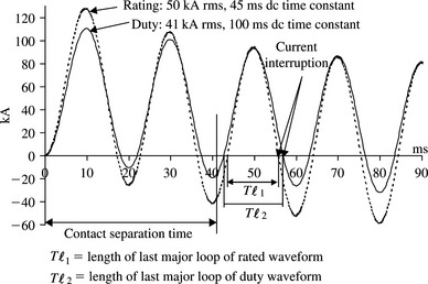
Figure 7.9 Illustration of the effect of large duty dc time constant on circuit-breaker short-circuit rating
 (7.35a)
where
and v(t) and i(t) are instantaneous arc voltage and instantaneous arc current, respectively, t2 – t1 is the arcing time duration or, more usually, the duration of the last major current loop before interruption. If available, a circuit-breaker arc model may be used since this accurately represents the time-dependent non-linear variation of the arc resistance and hence arc voltage. Where such a model is not available, two simplified options exist. The first is to assume that the arc voltage is constant and the arc energy is therefore proportional to
 (7.36a)
The second is to assume that the arc resistance is constant and the arc energy is therefore proportional to
 (7.36b)
Current international consensus in both IEC and IEEE Standards is that where the symmetrical short-circuit current duty is less than 80% of the rated symmetrical short-circuit current, then a circuit-breaker tested with a time constant of 45 ms may be considered adequate for any higher time constant except where current zeros are delayed for several cycles. For short-circuit duties above 80%, IEEE allows the use of the derating (correction) method described in Section 7.4.3 provided that the time constant does not exceed 120 ms (X/R = 45.2 at 60 Hz).
For short-circuit duties above 80%, IEC 62271–308:2002 Guide for Asymmetrical Short-Circuit Breaking Test Duty T100a includes a criterion when the duty time constant exceeds the standard test time constant of the circuit-breaker The criterion is a measure of the arc energy and is based on the product ![]() where
where ![]() and
and ![]() are the peak and duration of the last short-circuit major current loop, before interruption, respectively. The IEC Guide may be applied such that if the energy represented by the
are the peak and duration of the last short-circuit major current loop, before interruption, respectively. The IEC Guide may be applied such that if the energy represented by the ![]() area under the duty current curve is less than that of the rated current curve, the duty is judged to be within rating and current interruption is deemed successful. For example, from Figure 7.9, and considering the third major current loop, we have
area under the duty current curve is less than that of the rated current curve, the duty is judged to be within rating and current interruption is deemed successful. For example, from Figure 7.9, and considering the third major current loop, we have
The corresponding circuit-breaker rating is equal to
Therefore, the (50 kA rms, Tdc = 45 ms) circuit-breaker is not capable of breaking a duty of (41 kA rms, Tdc = 100 ms). It is interesting to note the corresponding duty and rating values for the second major current loop. These are equal to
and
An alternative criterion is to evaluate the total arc energy that corresponds to the last major loop of both the rated and duty current waveforms using Equation (7.36). A trade-off between the ac and dc components of the total asymmetric instantaneous currents can then be calculated so that the total arc energy of the major loop duty current is equal to that of the rated or tested current. In addition, the increase in the last major loop arc duration may be conservatively limited to a small amount of 10–15% compared to the major loop arc duration of the rated current. This method enables the calculation of effective derating factors that may be applied to the rated symmetrical short-circuit current of the circuit-breaker.
[1] IEC 60909-0:2001–2007, Short-Circuit Currents in Three-Phase AC Systems—Part 0: Calculation of Currents. 1st end.
[2] IEC 60909-1:2002, Short-Circuit Currents in Three-Phase AC Systems—Part 1: Factors for the Calculation of Short-Circuit Currents.
[3] . Engineering Recommendation ER G 7/4. Procedure to Meet IEC 60909 for the Calculation of Short-Circuit Currents in Three-Phase AC Power Systems. UK: Electricity Network Association; 1992.
[4] IEEE Standard C37.010:1999, IEEE Application Guide for AC High-Voltage Circuit Breakers Rated on Symmetrical Current Basis.
[5] British Standard BSEN 62271-100:2001, High-Voltage Switchgear and Controlgear-Part 100: High-Voltage Alternating-Current Circuit-Breakers.
[6] IEC TR 62271-308:2002, High-voltage Switchgear and Controller-Part 308: Guide for Asymmetrical Short-Circuit Breaking Test Duty T100a.
[7] Bridger B. All Amperes are not created equal: a comparison of current ratings of high-voltage circuit breakers rated according to ANSI and IEC Standards. IEEE Transactions on Industry Applications. January/February 1983;Vol. 29(No. 1):195-201.
[8] Hartman C.N. Understanding asymmetry. IEEE Transactions on Industry Applications. July/August 1985;Vol. 1A-21(No. 4):842-848.
[9] Knight G., et al. Comparison of ANSI and IEC 909 short-circuit current calculation procedures. IEEE Transactions on Industry Applications. May/June 1993;Vol. 29(No. 3):625-630.
[10] Rodolakis A. A comparison of North American (ANSI) and European (IEC) fault calculation guidelines. IEEE Transactions on Industry Applications. May/June 1993;Vol. 29(No. 3):515-521.
[11] Roennspiess O.E., et al. A comparison of static and dynamic short circuit analysis procedures. IEEE Transactions on Industry Applications. May/June 1990;Vol. 26(No. 3):463-475.
[12] Berizzi A., et al. Short-circuit calculation: a comparison between IEC and ANSI Standards using dynamic simulation as reference. IEEE Transactions on Industry Applications. July/August 1994;Vol. 30(No. 4):1099-1106.
[13] No. 11Cooper C.B., et al. Application of test results to the calculation of short-circuit levels in large industrial systems with concentrated induction-motor loads. Proceedings IEE. Vol. 116. November 1969:1900-1906.
[14] No. 4Cooper C.B., et al. Contribution of single-phase motors to system fault level. IEE Proceedings. Vol. 139. July 1992:359-364.
[15] . Calculation of electric power system short-circuits during the first few cycles. AIEE Committee Report, AIEE Winter General Meeting. New York. January/February 1956:120-127.
[16] . Calculated symmetrical and asymmetrical short-circuit current decrement rates on typical power systems. AIEE Committee Report, AIEE Winter General Meeting. New York. January/February 1956:274-285.
[17] Skuderna J.E. The X/R method of applying power circuit breakers. AIEE Winter General Meeting. New York. February 1959:328-338.
[18] Satou T., et al. Influence of the time constant of de. component on interrupting duty of gas circuit breakers. IEEE. 2001:300-305.
[19] Smeets R.P.P., et al. Economy motivated increase of de time constants in power systems and consequences for fault current interruption. IEEE. 2001:462-467.
[20] Shinato T., et al. Evaluation of interruption capability of gas circuit breakers on large time constants of dc component of fault current. CIGRE. 2002:13-104.