Chapter 1
Architectural Overview of SharePoint 2013
WHAT’S IN THIS CHAPTER?
- Understanding on-premise server farm architecture
- Deploying, configuring, and publishing applications with the service application architecture
- Discovering the improved scalability and redundancy of the search architecture
- Exploring the SQL Server database architecture
- Understanding the cloud-hosted architectures
Microsoft SharePoint Server 2013 introduces a lot of new functionality that you need to understand to write better applications on the SharePoint 2013 platform. Developing new functionality relies on a sound logical and physical architecture. Therefore, you must have a good appreciation and understanding of your SharePoint farm architecture to take advantage of and develop long-lasting SharePoint solutions.
This chapter provides a succinct overview of the common on-premise server farm architectures available for SharePoint 2013. You take a detailed look at service applications and dive into the evolved SharePoint 2013 search architecture. Then, you look at the improvements and updates related to the SQL database tier. Lastly, you take a look at the cloud-hosted farm architectures.
The content presented in this chapter targets architects, lead developers, and developers developing solutions tailored to their SharePoint 2013 farm topologies, but the chapter is also useful for anyone working with the product. Although all topics covered in this chapter are important, this chapter has been designed to enable you to jump to the sections you are interested in.
WHAT’S NEW FROM AN ARCHITECTURAL PERSPECTIVE?
From an architectural perspective there are a number of enhancements to the SharePoint 2013 topology. These additions and improvements continue to evolve the SharePoint platform capabilities to better handle the ever-increasing workload placed on the SharePoint platform. The key updates include:
- SQL improvements and shredded storage — A number of improvements have been made at the database layer to reduce the impact of scenarios that might invoke full table scans, improve usage of advanced indexing features in SQL Server 2008 R2 and SQL Server 2012, and incorporate a new feature called shredded storage that changes the way SharePoint stores and updates files in SQL. Files are now shredded, and only the changed pieces are updated at the database layer. This reduces the impact caused by document updates.
- Distributed cache service — A new cache service, based on Windows Server AppFabric Distributed Caching, has been implemented in SharePoint 2013. By default it is enabled on all web front ends and application servers. It improves performance by caching information such as social data authentication tokens.
- Unified search architecture — SharePoint 2013 unifies the search offerings available in SharePoint 2010. SharePoint 2013 search provides numerous improvements to content crawling, content processing, analytics processing, indexing, query processing, and search administration components.
- Integrated Request Management (RM) — Request Management provides SharePoint more knowledge and control over incoming requests. This includes throttling and routing requests to appropriate web front ends, prioritization and filtering of requests, and load balancing based on weighting schemes.
- New service applications — New service applications include the App Management Service to support and manage apps in SharePoint 2013, the Machine Translation Service that supports automated language translation of files, and the Work Management Service that provides task aggregation functionality.
- Office Web Applications is now a separate product — Office Web Applications have been split into a dedicated product to provide a uniform application for viewing and editing files, including files not necessarily in SharePoint. The Office Web Apps Server supports the Web application Open Platform Interface (WOPI) that SharePoint implements to support office files hosted in SharePoint.
- Web analytics platform — The web analytics platform replaces the web analytics service application that was in SharePoint 2010. It has been completely redesigned and integrated into the search service application of SharePoint 2013.
- Windows Azure Workflow — Windows Azure Workflows are now supported for on-premise and hosted deployments in SharePoint 2013.
ON-PREMISE SERVER FARM ARCHITECTURE
Server farms represent the topology that delivers SharePoint services to end users. A server farm is a collection of server machines acting together to host SharePoint services and workloads.
SharePoint 2013 provides a high degree of flexibility for planning your topology. The core principle behind implementing a server farm is the ability to scale the environment as required to support additional workloads, scenarios, and load placed on the farm by your organization.
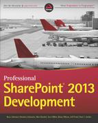
Farms can range in size from a single SharePoint server to highly scaled-out architectures hosting server roles on dedicated sets of physical servers. Figure 1-1 shows a typical medium SharePoint server farm, as published in the TechNet article “Topologies for SharePoint Server 2013: Model” (http://go.microsoft.com/fwlink/p/?LinkId=259119).
Each tier in a topology represents the purpose of the server machines hosted within it, or the services dedicated to those server machines. The core components of a server farm can be categorized into the following three tiers (refer to Figure 1-1):
- Web servers — Web servers are servers that respond to user requests and render the SharePoint web pages. All web servers in a farm are mirrors of each other and are load balanced.
- Application servers — Application servers are used to describe any server that runs back-end application services (for example, servers that host search crawl and query components). Multiple redundant application servers can be load balanced.
- Database servers — The database tier hosts nearly all the data of your farm in SQL databases. This includes configuration databases, service application related databases, and content databases. All databases can be assigned to one database server or spread across multiple servers.
SharePoint 2013 can be deployed in a number of topology configurations. The basic topologies include small, medium, and large — otherwise known as single-tier, two-tier, and three-tier deployments — that define the placement and purpose of individual server machines in your server farm’s topology.
Web Server Tier
The web server tier is composed of web servers or other servers that receive and respond to HTTP requests. Web servers host SharePoint web applications in Internet Information Services (IIS). They can support additional services such as the search query component sending requests to database servers in the database server tier, or communicating with application servers in the application server tier to consume services hosted on those servers. Servers in the web server tier are exposed directly to end users and should be secured behind a firewall or within a perimeter network.
Application Server Tier
The application server tier is an optional tier composed of servers that are dedicated to the hosting of service applications associated with SharePoint 2013. Examples of servers in the application server tier include dedicated server machines that host the search service, administration, and query components, in addition to services such as PerformancePoint or Excel Services.
The application server tier is most commonly associated with large server farm environments, in which dedicated compute resources are required to support high search query volumes, large indexes, or to isolate service applications to free up resources on the web server tier to support high concurrency rates.
Database Server Tier
The database server tier is composed of servers hosting SQL Server. Database servers in the database tier respond to requests initiated by web and application servers, and update the underlying databases that support SharePoint 2013. The database server tier can be scaled both up (to improve performance) and out (to improve performance and provide additional server farm resiliency).
Small or Single-Tier Topology
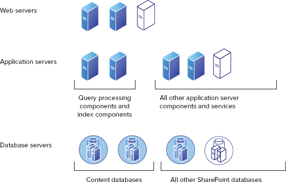
A small or single-tier topology commonly consists of a single server deployment in which all components required to instantiate a SharePoint environment are installed on one machine including the database server. Figure 1-2 shows an example of a single-tier topology, which is designed to support development or small businesses where scale and redundancy are not concerns.
A single-tier topology does not provide any level of redundancy. Therefore, it requires an aggressive backup-and-restore strategy to be implemented because this is the extent of data protection that can be provided in this deployment topology. Because all components are installed on a single server, single-tier topologies are the least flexible and do not support seamless scale.
Medium or Two-Tier Topology
A medium or two-tier topology consists of two or more servers that support separation of SharePoint and SQL Server components. This includes one or more web servers installed with SharePoint 2013, and one or more database servers installed with SQL Server. Medium or two-tier topologies benefit from their flexibility in that they can seamlessly scale to meet the changing business needs or the demands of the organization.
Figure 1-3 shows a minimal two-tier topology composed of one web server running SharePoint Server 2013 in the web tier and one database server running SQL Server 2008 R2 SP1 or SQL Server 2012 in the database server tier.

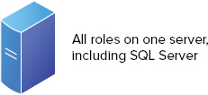
Figure 1-4 shows a scaled, two-tier topology that includes two load-balanced web servers running SharePoint Server 2013 in the web server tier and two database servers running SQL Server 2008 R2 SP1 or SQL Server 2012 in the database server tier that can be clustered or mirrored to provide high availability and redundancy.
The two-tier topology provides the most flexible deployment type and is recommended for organizations of all sizes as a base topology. This topology can be expanded or contracted through the addition or removal of server machines. As such, it is one of the most common deployments of a server farm, providing a flexible and scalable solution. A two-tier server farm enables an organization to seamlessly implement hardware or software load balancing such as Windows NT Load Balancing Service (WLBS) to distribute incoming HTTP requests evenly between web servers. This provides a means to handle an increase in demand as the number of requests submitted to it rise (for example, as the result of a merger or acquisition).
A two-tier server farm can also seamlessly scale at the database server tier through the introduction of additional database servers in a mirrored or clustered configuration. This provides additional resiliency and distribution of load within a server farm environment.
Large or Three-Tier Topology
A large or three-tier topology is designed for large organizations that require performance, scale, and adherence to strict business-continuity management objectives.
Figure 1-5 shows a three-tier topology that consists of two or more web servers installed with SharePoint 2013, one or more application servers installed with SharePoint 2013, and two or more database servers installed with SQL Server.

The physical topology selected for SharePoint 2013 can drive the layout of the service application topology. In many cases, it may be easier to map the service-application topology to a physical topology to help ensure that sufficient resources exist to support the overall deployment.
Geographically Distributed Topology
Geographically dispersed deployments refer to distributing SharePoint resources to support regional or global users. For example, an organization may have its headquarters in Seattle, Washington. However, many users may be distributed globally to support various corporate functions, or to respond to opportunities in specific geographic locations.
In this scenario, it can be costly to deploy a dedicated instance of SharePoint 2013 to support small pockets of users. Therefore, the organization may opt to introduce WAN optimization devices, whether symmetric or asymmetric, to accommodate latency or leverage technologies such as BranchCache in Windows Server 2008 R2 or Windows Server 2012.
In scenarios in which the geographically dispersed user base is substantial enough to justify the cost of a localized, dedicated SharePoint 2013 deployment, an organization can opt to federate or publish service applications from the centralized server farm to the distributed regional server farms. This provides a unified experience to the remote user base. You could optionally isolate these server farms to support regulatory compliance related to those specific geographic locations.
SERVICE APPLICATION ARCHITECTURE
This section focuses on helping you understand services in SharePoint 2013. The objective is to make you familiar with the service application architecture in SharePoint 2013, and how this architecture is used in the platform to offer new and improved functionality.
Service Application Model
SharePoint 2013 uses the service application model first introduced in SharePoint 2010. Starting with SharePoint 2010 and continued in SharePoint 2013, SharePoint Foundation 2013 provides the infrastructure for hosting service applications. Figure 1-6 shows the service application model in SharePoint 2010 and 2013.

The idea with the service application model in SharePoint 2013 is simple. If you don’t need a particular service application, you don’t deploy it to your farm — period! In addition, you can deploy multiple instances of the services. Actually, you can create as many instances of a given service application as you like.
The second layer of granular configuration with the service model comes at the web application level. In SharePoint 2013, web applications can be configured with the service applications they want to consume, and in which combination.
After you have an instance of a service application deployed to your farm, it can be shared across multiple web applications in the same farm, or even across different farms. Regardless of the sharing model, you can always modify the association between a web application and service applications at a later time.
Service applications can be deployed to different application pools to support process isolation. You can pick and choose which service applications should be within the same process, or within separate processes.
Figure 1-7 shows how various services are distributed in two application pools.
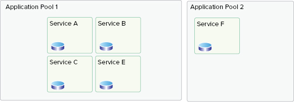
Although in most implementations, the performance of your farm is best optimized if services exist in one application pool; in some scenarios the highest physical isolation of services is required. The SharePoint 2013 service application model enables you to create separate instances of service applications and place them in different application pools.
Service applications provide a better scalability model. You can select which servers host and run a particular service application service using the Services on Server page in Central Administration.
SharePoint 2013 provides a basic load balancer that uses a round-robin algorithm to send requests to service applications. When a web application requests an endpoint for an associated service application (through a proxy), the out-of-the-box load balancer returns the first available endpoint. Certain services (such as Excel Calculation Services) provide their own software load-balancing feature to ensure that no instance of a given service is overloaded at any time.
SharePoint 2013 supports cross-farm service applications. In other words, any farm can both publish and consume service applications from other farms. Each farm can consume services from more than one parent farm. This enables web applications in your SharePoint 2013 farm to use both local and remote service applications.
Available Service Applications
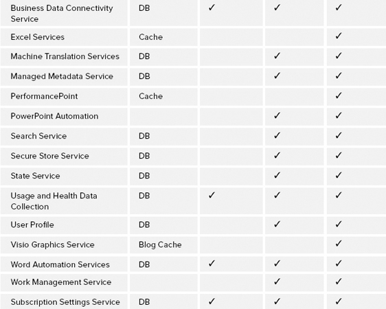
As an architect or developer, you must know what service applications your licensed edition of SharePoint provides. Table 1-1 provides an overview of all the service applications that ship out-of-the-box with different editions of SharePoint 2013, excluding service applications provided by other Microsoft products such Project Server, PowerPivot service, and so on.
TABLE 1-1: Service Applications Available by SharePoint 2013 Editions
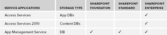
Following are descriptions of each service application:
- Access Services — This service application enables you to create, view, edit, and interact using either the access 2013 office client or in the browser.
- Access Services 2010 — This service application enables continued maintenance of SharePoint 2010 Access service applications by using Access 2010 and 2013 Office clients. It does not enable users to create new applications.
- App Management Service — The App Management Service enables you to install apps from the internal App Catalog or the public SharePoint store.
- Business Data Connectivity Service — The Business Connectivity Service (BCS) enables you to upload data (BDC) models that define interfaces of other enterprise line-of-business (LOB) systems and enables connectivity to those systems.
- Excel Services — This service application enables viewing and interacting with Excel files from within the browser.
- Machine Translation Services — This service provides automatic machine translation of files and sites.
- Managed Metadata Service — This service application enables you to manage taxonomy hierarchies, keywords, and social tagging features of SharePoint 2013. This service application also handles content-type publishing across site collections.
- PerformancePoint — This service application supports configuration and monitoring of PerformancePoint as a business intelligence (BI) product integrated with the Enterprise edition of SharePoint 2013.
- PowerPoint Automation Service — This service application enables server-side presentation conversions to and from a variety of file formats.
- Search Service — As its name implies, this service application (which comes with its own topology management configuration) is used to index content and serves search queries performed by users or custom code.
- Secure Store Service — This is a credential mapping service to access other enterprise-level service applications or back-end enterprise systems.
- State Service — The State Service provides temporary storage of any data that deals with a user session.
- Usage and Health Data Collection — This service application provides storage usage and health information at the farm level, and provides various reporting functionality on such data.
- User Profile — This user profile service application is one of the core service applications in SharePoint 2013. This service application supports features such as My Sites, My links, Colleague tracker, profile pages, personal tags and notes, and other social features.
- Visio Graphics Service — This service application enables viewing, interacting, and refreshing of Visio diagrams within a browser.
- Word Automation Services — This service application enables you to view and edit Word documents in a web browser. It can also be used for document conversions.
- Work Management Service — This Work Management Service enables key user-related information to be aggregated to a central location. The service supports a provider model to enable other systems to leverage this service.
- Subscription Setting Service — This is the key enabling component of the Multitenancy features provided by the SharePoint 2013 platform.
Now that you are familiar with service applications in different editions of SharePoint, consider the life cycle of a service application.
Service Application Life Cycle
A typical life cycle for a service application consists of several stages. When you plan your service application, consider each stage of this cycle. For example, you should understand when you should use the Configuration Wizard to provision your service applications or use Windows PowerShell, and when you should create a custom proxy group for your service applications.
Figure 1-8 shows the stages in a life cycle for a service application.

Starting Services
Although service applications are different from services, they still confuse many people working with SharePoint 2013.
If you browse to the Services on Server page in SharePoint Central Administration, that page lists all services that can be started and stopped on specific servers of the farm, as shown in Figure 1-9.
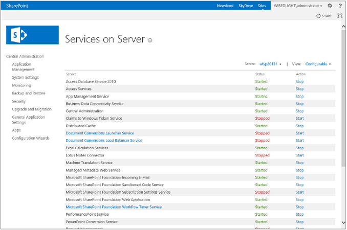
These services are mostly SharePoint wrappers around Windows services and may or may not have an associated service application. For example, Central Administration is just a service that can be started on a server of the farm to turn it into a server that can host the Central Administration site — there is no service application associated with it.
As mentioned earlier in this chapter, a service application represents a specific instance of a given service that can be configured and shared in a particular way. Service applications are composed of Windows services, timer jobs, caching, SQL databases, and other stuff. They are just a broader concept than Windows services.
Deploying Service Applications
You can deploy service applications within a farm by using the following methods:
- Selecting the service applications in the Initial Configuration Wizard of your farm
- Adding new service applications or new instances of the existing service application in the Central Administration site
- Using Windows PowerShell
Table 1-2 describes the Windows PowerShell commands that you can use to manage service applications.
TABLE 1-2: Service Application Windows PowerShell Commands

Regardless of your deployment approach, service applications can be isolated. To do so, during the provisioning process, you can either specify to use an existing application pool, or create a new application pool and have the service application run in its own worker process.
Configuring Service Applications
After the service applications are configured at the farm level, they can all be managed in the Central Administration site. When you click Manage Service Applications, you are taken to the Service Applications page, as shown in Figure 1-10.

In the Service Applications page, you should note three things:
- All deployed service applications are listed.
- All service application connections (proxies) are listed.
- You can add new service applications by clicking the New button on the Ribbon.
When service applications are provisioned, if you open up the Internet Information Services (IIS) manager, you can see that there is a web application called SharePoint Web Services, and underneath that web application are a bunch of virtual directories. Each of those virtual directories is seen by a globally unique identifier (GUID), or its identifier for the service application, as shown in Figure 1-11.
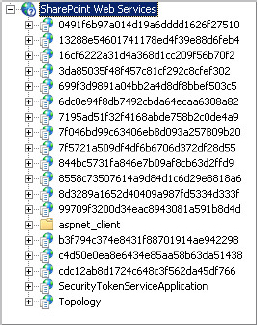
At a service database level, most of the service applications use their own set of databases.
One issue with configuring service applications using the Configuration Wizard is that the associated virtual directory databases can end up having a lot of GUIDs. For example, the name for one of the User Profile databases could be User Profile Service Application_ProfileDB_899fd696a54a4cbe965dc8b30560dd07.
Though this might be acceptable in some cases, generally, a more intuitive naming convention makes a more sense. One way to resolve this issue is to use the Manage Service Applications page in the Central Administration site to add service applications individually and then specify meaningful database names. The other alternative approach is to use Windows PowerShell to provision your service applications.
The following code snippet shows how you can provision a State Service service application using Windows PowerShell. Note how the SQL Server database and server name are specified in the code.
New-SPStateServiceDatabase -Name "StateServiceDatabase" -DatabaseServer
     "dhsqlsrv" | New-SPStateServiceApplication -Name "State Service Application"
     | New-SPStateServiceApplicationProxy -Name " State Service Application Proxy"
     -DefaultProxyGroup > $null
As mentioned previously, you can create and deploy your own service application. In that case, you can override the previous Windows PowerShell commands and add your own parameters.
Configuring Service Application Proxies
If you deploy your service applications using either the Configuration Wizard or via Central Administration, service-application proxies are automatically created for you. If you use Windows PowerShell, then you must also manually create the proxy that goes along with that service application.
So, what’s the service application proxy, anyway?
Essentially, the service application proxy is a virtual link that connects web applications to a particular service application. So, when you create your web application, you can specify your association to a service-application proxy, and it’s the proxy that actually manages the communication back and forth.
In addition to linking web applications to service applications, some proxies also include settings that can be modified independently from the service applications. For example, the proxy for the Managed Metadata Service application indicates whether the associated service application is the default storage location for the corporate taxonomy store (such as keywords and column-specific term sets), as shown in Figure 1-12.

Configuring Proxy Groups
As its name implies, a service application proxy group is a grouping for service application proxies that are selected for a Web application. A single service application proxy can be included in multiple proxy groups, or a proxy group may choose not to include a service application proxy based on the requirements of the target Web applications.
When you set up your farm, a default proxy group is created that includes all service application proxies. During the creation of a Web application, you have your choice to select the default proxy group or create a custom proxy group. Figure 1-13 shows the list of service applications configured in the default proxy group.

From Windows PowerShell you can run the Get-SPServiceApplicationProxy cmdlet, as shown in Figure 1-14, and that lists the service application proxy IDs. You can then use Remove-SPServiceApplicationProxy (which takes the ID as a parameter) and Add-SPServiceApplicationProxyGroupMember to remove a service application proxy, or to add a member to the service application proxy group.

Consuming Service Applications
By default, all web applications in the local farm are associated with the default proxy group. This means that consuming the services in the local farm is not something that you must worry about, and it’s automatically set up for you. If you decide to create a custom proxy group, you must decide how you want a specific web application to consume service applications.
To change the default proxy group for a web application, you must select Application Management in the Central Administration site, and click Configure Service Application Associations. In the Service Application Association page, you can see the default text under the Application Proxy Group heading. If you click it, you go to a page where you can manage the members of that default proxy group. In addition, if there were any custom proxy groups for each web application, they would be listed in the same page.
Again, it’s worth mentioning that some connections might include settings that can be modified. For example, if a web application is connected to multiple instances of the Managed Metadata Service, you must indicate which service application hosts the corporate taxonomy.
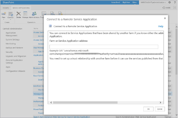
Publishing Service Applications
A service application can be consumed with one or more web applications within the local farm, or it can be consumed by web applications in a remote farm.
Before going into more detail, consider some terminology to ensure that you have a clear understanding:
- Publishing a service application — This means making a service application available for consumption across farms.
- Cross-farm service application — This is a service application made available to be consumed by remote farms.
At a high level, three things must happen to deploy service applications across farms:

Not all service applications can be shared between farms. For example, BCS is a cross-farm service application, whereas other service applications are not designed to be shared between farms. Some cross-farm service applications are not recommended for use in wide area network (WAN) environments. Simply put, those cross-farm service applications that use Windows Communication Foundation (WCF) endpoints are the ones that use ASMX web service.
Table 1-3 lists current recommendations for deploying service applications across farms or over a WAN.
TABLE 1-3: Recommendations for Deploying Service Applications
| SERVICE APPLICATIONS | CROSS-FARM | WAN-FRIENDLY |
| Access Services | No | N/A |
| Access Services 2010 | No | N/A |
| App Management Service | No | N/A |
| Business Data Connectivity Service | Yes | With limitations |
| Excel Services | No | N/A |
| Machine Translation Services | Yes | Yes |
| Managed Metadata Service | Yes | Yes |
| PerformancePoint | No | N/A |
| PowerPoint Automation | No | N/A |
| Search | Yes | Yes |
| Secure Store Service | Yes | No |
| State Service | No | N/A |
| Usage and Health Data Collection | No | N/A |
| User Profile | Yes | No |
| Visio Graphics Service | No | N/A |
| Word Automation Services | No | N/A |
| Work Management Service | No | N/A |
| Subscription Settings Service | No | N/A |
MULTITENANCY HOSTING ARCHITECTURE
Multitenancy is the ability to host unique deployments for multiple tenants on the same SharePoint 2013 server farm by isolating the data, operational services, and management of a tenant from other tenants using the same farm.
The traditional (and most accurate) definition of Multitenancy is a single instance of software that services multiple organizations or clients, virtually partitioning its data and configuration, which enables clients to work within a customized application instance. The features and capabilities delivered by SharePoint Server 2013 contribute to supporting true multitenant architectures that are useful not only to hosting providers, but also equally to the enterprise.
When carefully planned and applied within the enterprise, Multitenancy is one of many solutions that contribute to reduced cost, complexity, and overall management.
In SharePoint 2013, multitenancy requires configuring the server farm, and its service applications, to support multiple tenants. To achieve Multitenancy–based architectures requires a combination of the following key capabilities:
- Site subscriptions
- Service application partitioning
- Tenant administration
- Feature packs
Now look at each of these in more detail.
Site Subscriptions
Site subscriptions are the core of the hosting feature set in SharePoint 2013. Site collections are grouped together by their subscription ID, which forms the basis of the tenant. The subscription ID is used to map features, settings, and service partitions to tenants. In other words, site subscriptions can be loosely described as a collection of sites that subscribe to a set of service partitions, settings, and individual features. Site subscriptions are also known as tenants.
You can approach site subscriptions as a loose association of content. In the object model, site subscriptions are represented through Microsoft.SharePoint.SPSiteSubscription.
The limitations and constraints of this are as follows:
- Site collections grouped within a site subscription cannot span farms.
- Site subscriptions with site collections that span web applications cannot be managed through the Tenant Administration template. (More information about this is described in the section “Tenant Administration.”)
- Multiple site subscriptions are supported within a single web application and content database.
- Services can be partitioned and served to specific tenants to enable granular data isolation.
- Tenants can consume non-partitioned services.
Service Application Partitioning
Data, usage, and operational isolation are provided through new service application capabilities. The capability to partition many of the SharePoint 2013 service applications enables individual and unique tenants to consume the service application, while maintaining logical separation from other tenants also consuming from the partitioned service application.
To create a new partitioned service application in SharePoint Server 2013, an administrator must follow these steps:
Figure 1-17 shows the relationships between these concepts in a hosting model.

SharePoint 2013 uses the Subscription ID for the site subscription to map to the Partition ID, which represents the subset of data exposed to the tenant.
Figure 1-18 shows a practical implementation of Multitenancy in SharePoint 2013. This implementation has one web application with two tenants, each owning a few site collections within the same web application. The web application consumes service applications that are multitenant-aware, and service data for each tenant is partitioned in the back-end database (that is, data isolation). Although both tenants use the same service application, they have no visibility to the other tenant’s data because the service data is partitioned.
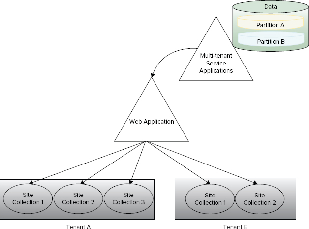
Two things about the Figure 1-18 are highlighted here:
First, not all service applications can be partitioned. That’s because some services do not need to store tenant data, so they can be shared across multiple tenants without risk of exposing tenant-specific data. Table 1-4 lists the service applications that don’t include the capability to be partitioned. Second, a service application that cannot be partitioned is not a multi-tenant aware service application.
TABLE 1-4: Service Applications That Cannot Be Partitioned
| SERVICE APPLICATIONS | MULTITENANT-AWARE |
| Access Services | No |
| Access Services 2010 | No |
| App Management Service | No |
| Business Data Connectivity Service | Yes |
| Excel Services | No |
| Machine Translation Services | Yes |
| Managed Metadata Service | Yes |
| PerformancePoint | No |
| PowerPoint Automation | No |
| Search | Yes |
| Secure Store Service | Yes |
| State Service | No |
| Usage and Health Data Collection | No |
| User Profile | Yes |
| Visio Graphics Service | No |
| Word Automation Services | Yes |
| Work Management Service | No |
| Subscription Settings Service | Yes |
Service Applications can be configured to partition data that resides in a single database.
If you decide to keep all your tenants in one web application using different site collections, several new or improved site collection features are at your disposal:
- Additional support is provided for vanity domains using host header site collections (that is, multiple root-level site collections within a web application).
- Host header site collections support managed paths. (For example, site collections http://foo.com and http://foo.com/sites/foo for tenant A, and http://bar.com and http://bar.com/sites/bar for tenant B can coexist in the same web application.)
- Additional wildcard is now available for managed host header paths in SharePoint 2013.
- Load balancer Single Sockets Layer (SSL) termination support is included.
- The Windows PowerShell cmdlet New-SPSite accepts a parameter that enables you to target a site collection to reside in a specific content database.
- Pluggable custom code (Site Creation Provider) enables you to enforce database organization across all your tenants. This is basically to ensure that if a tenant creates a new site collection, that site collection ends up in the database you want, not just following the out-of-the-box, round-robin algorithm.
- Sandboxed solutions enable each tenant to deploy custom code to their own site collections.
Although partitioned service applications and new features of site collections in SharePoint 2013 play an important role in the overall multi-tenant architecture, in reality, many features enable Multitenancy in SharePoint 2013. Following are some of these features:
- Microsoft SharePoint Foundation Subscription Settings Service adds multitenant functionality for service applications (available in all editions of SharePoint).
- Feature sets are groups of product features allowed by farm administrators for tenants to activate and use.
- Site subscriptions are a logical group of site collections that can share settings, features, and service data. Each site subscription has a subscription ID that is used to map features, services, and sites to tenants, as well as partitioning their service data.
- Centralized and delegated administration allows the delegation of certain Central Administration tasks to tenant administrators using their own administration user interface, while the main Central Administration site is used to administer the entire SharePoint installation.
Tenant Administration
The management of site subscriptions occurs through a new administration site template, Tenant Administration, which is used to manage many aspects of the site collections that consume services from their assigned subscription. Multiple tenants are supported within a single server farm environment, which enables IT administrators to centrally manage the deployment of both features and capabilities. In addition, the IT administrator can delegate specific administrative control of site collections contained within a tenant, to the respective owner or business administrator.
For example, in a hosting scenario, the organization hosting the server farm environment manages farm-level settings and configurations. The consumer (or tenant) can manage the site collections, and, specifically, delegated features and capabilities (such as services). Figure 1-19 shows the Tenant Administration user interface.
To create a new site subscription object in SharePoint Server 2013, an administrator must create an SPSiteSubscription object and then create and add an SPSite object to SPSiteSubscription.
To create a new SPSiteSubscription object, follow these steps:
$subscription=New-SPSiteSubscription

$site=New-SPSite -Url http://AdventureWorks.com/sites
  /TenantAdministration -Template TenantAdmin#0
  -OwnerEmail [email protected]
  -OwnerAlias DomainUsername
  -SiteSubscription $subscription
Set-SPSiteAdministration -Identity http://AdventureWorks.com/sites
  /TenantAdministration
  -AdministrationSiteType TenantAdministration
Feature Packs
Feature packs are a method that enables the developer to group a collection of individual features (site- or web-scoped) into a larger overall package. Feature packs provide functionality or capabilities to individual site subscriptions in a multitenant model, enabling or preventing access to certain functionality or solutions on a tenant-by-tenant basis.
SEARCH ARCHITECTURE
SharePoint Server 2013 search architecture has been greatly improved with a new set of components to improve scalability and redundancy provided by the SharePoint server farm.
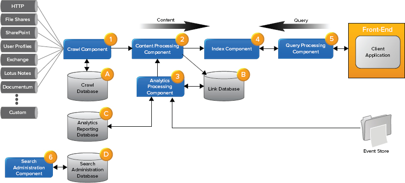
As you can see in Figure 1-20, the search architecture of SharePoint Server 2013 is now spread across four primary areas: crawl and content processing, analytics, index and query processing components, and search administration.
Now let’s have a look at each of these areas in more detail.
Crawl and Content Processing Components
In SharePoint Server 2013, the crawl and content processing architecture is responsible for crawling content from support content sources, delivering crawled items and their meta data to the content processing component, and processing the content. These break down into the following components
- Crawl component — The crawl component crawls configured content sources using the associated connectors and protocol handlers for the target content source. The actual content and associated meta data is then passed to the content processing component.
- Crawl database — The crawl database is used by the crawl component to store information about crawled items and to track information and history of crawls that have taken place.
- Content processing component — The content processing component receives items, processes and parses items using format handlers and iFilters, and transforms items into artifacts that can be added to the search index. This includes mapping extracted properties to properties defined using the search administration component.
- Link database — The Link database stores information relating to links and URLs found during the content processing process.
SharePoint Server 2013 crawl and content processing search architecture is flexible in that it enables you to scale out the crawl and content processing operations by seamlessly adding additional crawl component instances to your search topology.
Analytics Processing Component
In SharePoint Server 2013, the analytics processing component is now directly integrated into the search architecture and is no longer an individual service application. These break down into the following components
- Analytics processing component — The analytics processing component is responsible for processing search and user-based analytics. It performs search analytics by analyzing crawled items and usage analytics by analyzing how users interact with those items. For example, user interaction information is retrieved from the event store that has been aggregated from usage files on each of the web front ends in your server farm, and analyzed by the analytics processing component. This enables a wide range of sub-analyses to be performed.
- Content processing component — The content processing component receives search and user analytics results that in turn are used to update the index.
- Link database — The Link database stores information extracted by the content processing component. The analytics processing component updates the Link database to store additional analytical information, for example, the number of times an item was clicked.
- Analytics reporting database — The analytics reporting database stores the result of usage analysis.
SharePoint Server 2013 analytics processing search architecture is flexible in that it enables you to scale out analytics processing operations by seamlessly adding additional analytics component instances to your search topology. This enables analytics processing to complete faster.
Index and Query Processing
In SharePoint Server 2013, the indexing and query processing architecture is responsible for writing processed items received from the content processing component, handling queries and returning result sets for the query processing component, and moving indexed content based on changes to the search topology.
As shown in Figure 1-21, SharePoint Server 2013 search maintains an index of all processed content (including analytical information). The indexing component can scale using the following features:

- Indexing partition — Index partition is a logical portion of the entire search index. Index partitions enable horizontal scaling in that it enables you spread your entire index over multiple servers in your server farm.
- Index components — An individual index partition can be supported by one or more index components. These index components host a copy or replica of the index partition. A primary index component is responsible for updating the index partition, whereas passive index components are used for fault tolerance and increased query throughput. This, in essence, supports vertical scaling of your search topology.
- Query processing component — The query processing component is responsible for receiving queries from web front ends, analyzing and processing the query, and submitting the processed query to the index component.
Search Administration Component
In SharePoint Server 2013, the search administration component is responsible for running the system processes based on the configuration and search topology. The search administration component breaks down into the following components:
- Search administration component — The search administration component executes the system processes required for search, performs changes to the search topology, and coordinates activities of the various search components in your search topology.
- Search administration database — The search administration database stores search configuration information. This includes topology, crawl rules, query rules, managed property mappings, content sources, and crawl schedules.
Multi-Purpose (with Search) Medium-Sized Search Farm Topology Example
Figure 1-22 shows an example of a medium-sized search server farm topology. There are a few things to consider here. First, the term “medium-sized” refers to the number of items that can be handled by the search subsystems of the SharePoint topology. Second, although the farm shows the web tier and application tier, for this section ignore those and focus purely on the search-related aspects of this topology.
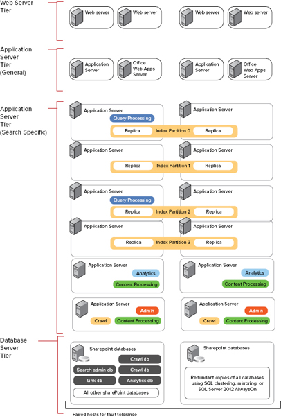
Third, this medium-sized search farm topology, based on the TechNet recommendation at http://www.microsoft.com/en-us/download/details.aspx?id=30383, can support approximately 40 million items in the index. Take a look at the key elements relating to this search topology:
- Search databases — Microsoft recommends fault tolerance at the database tier to keep your environment up in the case of a database tier failure. Although only one SQL cluster is recommended, keep in mind that the closer you get to 40 million items in the index, the more you should be thinking of moving search-related databases to a dedicated SQL cluster.
- Admin and crawl components — The admin and crawl components have been placed on two application servers. This provides fault tolerance to the administration components and increases capacity of the crawl operations over multiple servers.
- Content processing components — Items received from crawl operations are processed on four application servers. This contributes to decreasing the overall crawl time taken and thereby increases the search result freshness.
- Analytics components — The analytics component has been placed on two application servers. This provides fault tolerance in the event of failure of an application server hosting the analytics component.
- Indexing components — The global search index has been split into four partitions, and each partition resides on two application servers. This provides both fault tolerance and improves query latency and query throughput.
- Query processing — The query processing components have been placed on two application servers. This provides fault tolerance to the query processing components and increases the capacity to process queries received from the web server tier.
SQL SERVER DATABASE ARCHITECTURE
SharePoint Server 2013 relies heavily on well-planned and performant database tier. As a result, the Microsoft product group has invested heavily to improve the performance and manageability of the databases used by the SharePoint server farm.
Database Topologies
Determining the appropriate topology for your database server is an important step to ensure adequate overall SharePoint 2013 platform performance. As you begin to plan your hardware, you should understand that SharePoint 2013 is a 64-bit–only application and requires the 64-bit version of Windows and SQL Server products. Either SQL Server 2008 R2 Service Pack 1 or SQL Server 2012 are supported on Windows Server 2008 R2 Service Pack 1 or Windows Server 2012.
Single-Server Deployment
A single-server deployment configuration is recommended under the following circumstances:
- For small-to-moderate user volumes, and when the number of concurrent sessions is easily handled by the processing capability of the database server
- For developers who must develop custom solutions that integrate with SharePoint 2013
- When evaluating SharePoint 2013
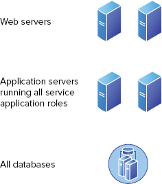
The single-server deployment configuration is the easiest to install and maintain. The default SQL Server installation options result in this deployment topology. During the evaluation, if you find that this deployment configuration meets the needs of your organization, you should continue with this deployment configuration, knowing that you can upgrade hardware or add additional server instances later when demand increases. Figure 1-23 shows an example of a single-server deployment configuration.

If you use a design based on a single SQL Server instance, you should consider the use of SQL Server connection aliases to allow seamless migration to a new database server topology (such as Failover Clustering or Database Mirroring).
Through the use of a connection alias, you can keep the application configuration the same. However, you must instruct the underlying operating system to look somewhere else for the database.
You can create an alias using one of two utilities:
- SQL Server Configuration Manager
- SQL Server Client Network Utility
Standard Server Deployment
In a standard server deployment, two database servers serve SharePoint databases in either a Failover Clustering or Database Mirroring design. Figure 1-24 shows an example of a standard server deployment configuration.
The standard deployment configuration is recommended for moderate user volumes where demand for processing is evenly spaced throughout the day, and the number of concurrent sessions is easily handled by the processing capability of the servers.
In addition to greater resiliency, the standard deployment scenario can offer improved performance over the single-server deployment. For example, in a Database Mirroring design, the load can be distributed across the principal and mirroring server, therefore mitigating common strains to include processing resources such as CPU time, memory, and disk access when they are hosted on the same computer. Some SharePoint operations are resource-intensive, so running these on separate servers can reduce the competition for processing resources. In addition, the footprint of a SharePoint database might be small at first, but disk space requirements and I/O subsystem utilization can grow significantly at run time.
When you are deciding whether to choose a single-server deployment or a standard server deployment, consider the following points based on your hardware configuration:
- Processing resources
- Memory resources
- Disk space availability
- I/O capacity
- Redundancy
If you find that this deployment configuration meets the needs of your organization, you should continue with this deployment configuration, knowing that you can upgrade hardware or add additional server instances later if demand increases.
Scale-Out Server Deployment
In a scale-out server deployment, multiple SQL Servers in a Failover Clustering or Database Mirroring configuration support SharePoint databases. Topologies include Active, Active, Passive (AAp) Failover Clustering topologies, or two distinct Database Mirroring pairs. Figure 1-25 shows an example of a scale-out server deployment configuration.

A scale-out deployment enables workload distribution in high-volume environments. In a scale-out deployment, each back-end database server in the deployment is referred to as a node.
A scale-out server deployment configuration is recommended for the following circumstances:
- For high-volume user loads, in which activity is measured in concurrent users, or in the complexity of operations that take a long time to process or render (such as high-capacity search scenarios)
- For high-availability scenarios, in which it is important that the SharePoint environment does not encounter unplanned downtime or become unavailable
- When you want to improve the performance of scheduled operations or service applications
By hosting your SharePoint databases on an instance that is part of a failover cluster, you can enhance the fault tolerance of your environment. Failover clustering is also possible for standard deployments, but typically there is less need for failover clustering when the environment is not configured for high-availability scenarios (such as environments with scale-out deployments).
You must determine and document carefully your availability needs, and test the solution to ensure that it provides the expected availability. Table 1-5 lists supported and non-supported high-availability configurations.
TABLE 1-5: Supported and Nonsupport High-Availability Configurations
| CONFIGURATION | SUPPORTABILITY STATEMENT |
| Failover Clustering | Supported |
| Log Shipping | Supported |
| Database Mirroring | Supported |
| Transactional Replication | Not Supported |
| Merge Replication | Not Supported |
| Snapshot Replication | Not Supported |
SharePoint 2013 Databases
If you’re new to SharePoint 2013, you may be astounded to see the number of databases used by SharePoint 2013. Don’t be alarmed; this is by design and is vital to the performance your SharePoint server farm. Table 1-6 provides an overview of the databases in SharePoint 2013.
TABLE 1-6: SharePoint 2013 Core and Related Databases


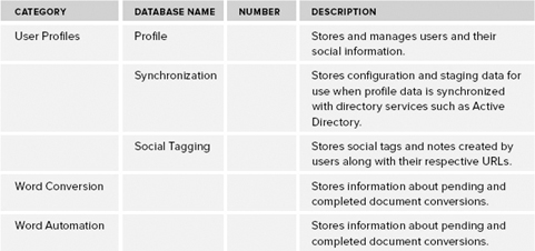
SharePoint 2013 uses a variety of databases (refer to Table 1-6). The databases in your environment depend on a combination of the SKU and service applications you deploy. With proper database planning, you can meet current and future needs related to scale and performance. Make sure you understand what each database purpose is, as well as its characteristics, to provide seamless scalability and performance required by your database server tier.
CLOUD-HOSTED ARCHITECTURES
SharePoint Online is available in two unique offerings (Standard and Dedicated) tailored to an individual organization’s size, requirements, and objectives — each provided at a per-user monthly fee. The SharePoint Online offerings can be differentiated at a high level based on capabilities, flexibility, and pricing.
SharePoint Online provides a rich feature set and collection of capabilities to both serve as an organization’s primary collaborative platform, to augment an organization’s existing on-premise deployment to support lightweight extranet or external sharing scenarios, or to enable collaboration outside of an organization’s firewall.
SharePoint Online delivers SharePoint 2013 as a cloud service through Microsoft data centers across the globe, enabling people to share ideas and expertise, build custom sites and solutions, and quickly locate information to respond to changing business needs — without the need to deploy SharePoint in their own data centers. In addition to the services and solutions provided by SharePoint, SharePoint Online provides high availability, comprehensive security, and simplified management, so organizations can be confident in choosing it for a collaboration platform.
SharePoint Online is designed to support some of the most complex user distribution patterns, whether users are centrally located or geographically dispersed. Without the need to purchase and deploy servers, organizations can quickly deploy SharePoint to remote offices, or support growth as the result of acquisitions. This flexibility enables users to quickly benefit from SharePoint with minimal cost and delay.
Security Features
SharePoint Online provides business-class reliability and flexibility through a set of features that ensure a secure collaborative environment. SharePoint Online provides the following set of common features:
- Secure access — SharePoint Online is provided through 128-bit Secure Sockets Layer (SSL) or Transport Layer Security (TLS) encryption.
- Intrusion — SharePoint Online is continuously monitored for unusual or suspicious activity.
- Audit — Microsoft regularly assesses the SharePoint Online infrastructure to ensure compliance policies and antivirus signatures are available. Configuration settings and security updates include the following:
- Achieved ISO 27001 certification
- Completed Statement on Audit Status (SAS) 70 Type I and II audits
- Added controls that assist customers in complying with Health Insurance Portability and Accountability Act (HIPAA) and Family Educational Rights and Privacy Act (FERPA)
- Achieved the European Union (EU) Safe Harbor seal
Identity Features
SharePoint Online provides multiple methods for the management and consumption of identity — whether a small-to-medium business without an existing identity infrastructure or a larger organization using Active Directory Domain Services (ADDS).
Organizations with an existing identity infrastructure such as ADDS can implement a Single Sign-On (SSO) approach to authentication by configuring Active Directory Federation Services (ADFS) to federate with the Microsoft Online Services Federation gateway. Users whose identities are derived from the federated domain can use their existing credentials to automatically authenticate to the service.
Microsoft Online Services provides the Directory Synchronization Tool to facilitate directory synchronization. The Directory Synchronization Tool provides one-way directory synchronization of all user accounts and mail-enabled contacts and groups from your local ADDS directory service to Microsoft Online Services. The Directory Synchronization Tool should be installed on a server joined to the ADDS Forest to be synchronized and capable of reaching all domain controllers for each domain in your forest.
Administration Model
Microsoft Online Services provides a delegated and granular administration model through role-based access. User accounts can be assigned either global or password administrator rights that provide either full access to all settings of the service, or the capability to read company and user information, reset user passwords, and manage support requests.
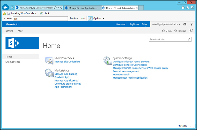
The administration of SharePoint Online occurs through a web portal where the SharePoint Online administrator creates and manages site collections, as shown in Figure 1-26.

The SharePoint Online administrative web portal is independent from the overall Microsoft Online Services administration portal. As shown in Figure 1-27, the SharePoint Online administrative web portal enables an administrator to manage site collections, configure Send To connections, configure InfoPath Forms Services and a web service proxy, manage user profiles, and manage the Term Store used by the service’s site collections.

SUMMARY
This chapter provides a broad view of the architecture in SharePoint 2013. It provides a good overview to help developers and architects understand where your customizations and add-ons “live.” Throughout the rest of the book, you learn more details about these new features and learn how to program against these features to build robust and capable SharePoint 2013 applications.