
C H A P T E R 8
Configuring Exadata
Oracle offers an optional service that handles the process of installing and configuring your Exadata Database Machine from start to finish. Many companies purchase this service to speed up their implementation time and reduce the complexity of integrating Exadata into their IT infrastructure. If you’re reading this chapter, you may be considering performing the configuration yourself, or perhaps you’re just interested in gaining a better understanding of how it’s done. The process we’ll discuss here closely resembles the installation process Oracle uses, largely because we will be using the same utility Oracle uses to configure Exadata. The utility is called OneCommand. It takes site-specific information you provide and performs the entire configuration from network, to software, to storage. When the process is complete, your Exadata Database Machine will be fully functional, including a starter database.
Exadata Network Components
Oracle database network requirements have evolved over the years, and with Exadata you will notice a few new terms as well as the addition of a new network. Traditionally, Oracle database servers required one public network link to provide administrative access (typically SSH), and database access (SQL*Net). With the introduction of 11gR2 Grid Infrastructure (formerly known as Oracle Clusterware), Oracle coined a new term for this network, the client access network. On the Exadata platform, administrative and database traffic have been separated with the creation of a new network for administrative access. This new network is known as the management network. The client access network is no longer accessible through SSH and is used only by the Oracle listener for incoming SQL*Net connections. In Exadata terms (and mostly in the context of configuration), these two networks are referred to as NET0 (management network), and NET1 (client access network).
The number and type of Ethernet ports on the compute nodes and storage cells varies between the V2, X2-2, and X2-8 models of Exadata. Hardware specifications for each model are detailed in the Exadata Database Machine Owner’s Guide. At a minimum, though, all models provide at least four embedded 1 Gigabit Ethernet ports. Oracle identifies these ports as NET0, NET1, NET2, and NET3. As noted, NET0 is used for the management network, and NET1 is used for the client access network. In RAC environments it is a common practice to bond two Ethernet devices together to provide hardware redundancy for the client access network. On Exadata, this is done by bonding the NET1 and NET2 ports together. The NET3 interface is unassigned and available to be configured as an optional network.
The Management Network
Exadata Database Machines have an Ethernet switch mounted in the rack that services the management network. The management network consists of the following links:
- One uplink from the management switch to your company's management network.
- One link to NET0 on each compute node and storage cell
- One link to the ILOM on each compute node and storage cell
- One link for the KVM
- One link for each of the two internal power distribution units (PDUs). This is optional and is only needed if you want to monitor electrical current remotely.
ILOM
In addition to the management network interface (NET0), compute nodes and storage cells come equipped with an Integrated Lights Out Manager (ILOM). The ILOM is an adapter card in each compute node and storage cell that operates independently of the operating system. The ILOM boots up as soon as power is applied to the server and provides Web and SSH access through the management network. The ILOM allows you to perform many of the tasks remotely that would otherwise require physical access to the servers, including gaining access to the console, powering the system off and on, and rebooting or resetting the system. Additionally, the ILOM monitors the configuration and state of the server's internal hardware components. The ILOM is linked via Ethernet port to the management switch within the Exadata enclosure.
KVM
Exadata also features an internal KVM (keyboard, video, and mouse) for managing the system. As you might expect, the KVM is a slide-out tray with a keyboard, touch pad, and flip-up monitor accessible from the front of the rack. The KVM also provides remote Web access to the operating system console of all compute nodes and storage cells. Like the ILOM, the KVM is linked via Ethernet port to the internal management switch.
![]() Note: The X2-8 model of Exadata does not come with a KVM. Compute nodes in V2 and X2-2 systems are a 2U form factor and on an Exadata full rack configuration take up a total of eight slots. The compute nodes (2) on the X2-8 occupy five slots each for a total of ten slots in the rack; displacing the 2U KVM switch.
Note: The X2-8 model of Exadata does not come with a KVM. Compute nodes in V2 and X2-2 systems are a 2U form factor and on an Exadata full rack configuration take up a total of eight slots. The compute nodes (2) on the X2-8 occupy five slots each for a total of ten slots in the rack; displacing the 2U KVM switch.
The Client Access Network
The client access network is used by the Oracle listener to provide SQL*Net connectivity to the databases. This network has traditionally been referred to, in RAC terminology, as the public network. One or two links (NET1, NET2) from each database server (compute node) connect directly to your corporate switch. Oracle recommends bonding NET1 and NET2 to provide hardware redundancy for client connections. If these ports are bonded, then each link should terminate at a separate switch to provide network redundancy.
The Private Network
The private network is serviced by the internal InfiniBand (IB) switches. This network manages RAC Interconnect traffic (cache fusion, heartbeat), as well as iDB traffic between the database grid and the storage grid. This network is self-contained within the InfiniBand network switch fabric and has no uplink to your corporate network. The network configuration can be found in the ifcfg-ib0 and ifcfg-ib1 configuration files in the /etc/sysconfig/network-scripts directory. They are configured as bonded devices, and the master device file is ifcfg-bondib0. For example, the following listing shows the Infiniband network configuration files from one of the database servers in our lab. Notice how the MASTER parameter is used to map these network devices to the bondib0 device.
/etc/sysconfig/network-scripts/ifcfg-bondib0

DEVICE=bondib0

USERCTL=no

BOOTPROTO=none

ONBOOT=yes

IPADDR=192.168.12.6

NETMASK=255.255.255.0

NETWORK=192.168.12.0

BROADCAST=192.168.12.255

BONDING_OPTS="mode=active-backup miimon=100 downdelay=5000 updelay=5000 num_grat_arp=100"

IPV6INIT=no

MTU=65520


/etc/sysconfig/network-scripts/ifcfg-ib0

DEVICE=ib0

USERCTL=no

ONBOOT=yes

MASTER=bondib0

SLAVE=yes

BOOTPROTO=none

HOTPLUG=no

IPV6INIT=no

CONNECTED_MODE=yes

MTU=65520


/etc/sysconfig/network-scripts/ifcfg-ib1

DEVICE=ib1

USERCTL=no

ONBOOT=yes

MASTER=bondib0

SLAVE=yes

BOOTPROTO=none

HOTPLUG=no

IPV6INIT=no

CONNECTED_MODE=yes

MTU=65520
Notice that the MTU size for the IB network devices is set to 65,520 (bytes). MTU stands for Maximum Transmission Unit and determines the maximum size of a network packet that may be transmitted across the network. Typical Ethernet networks support an MTU size of up to 1,500 bytes. In recent years, the Jumbo Frames technology has become a popular way to improve database performance by reducing the number of network round trips required for cache fusion between cluster nodes in an Oracle RAC cluster. Conventionally Jumbo Frames supports an MTU of up to 9,000 bytes. But some implementations may support an even larger MTU size.
![]() Note: Only the database servers are configured with a 64K MTU. Presumably this is to benefit TCP/IP traffic between the database servers, and between the database servers and any external host that is linked to the IB switch. You may be surprised to know that the IB ports on the storage cells are configured with the standard 1,500 byte MTU size. The large MTU size is not necessary on the storage cells, because I/O between the database grid and the storage grid utilizes the RDS protocol, which is much more efficient for database I/O and bypasses the TCP/IP protocol stack altogether.
Note: Only the database servers are configured with a 64K MTU. Presumably this is to benefit TCP/IP traffic between the database servers, and between the database servers and any external host that is linked to the IB switch. You may be surprised to know that the IB ports on the storage cells are configured with the standard 1,500 byte MTU size. The large MTU size is not necessary on the storage cells, because I/O between the database grid and the storage grid utilizes the RDS protocol, which is much more efficient for database I/O and bypasses the TCP/IP protocol stack altogether.
About the Configuration Process
Configuring Oracle database servers has always been a manual and somewhat error-prone process, especially for RAC environments. Exadata can be configured manually as well, but the complexities of the platform can make this a risky undertaking. Oracle has greatly simplified the configuration process by providing a utility called OneCommand. This tool uses input parameters you provide, and it carries out all of the low-level tasks for you. Even so, gathering all the right information required by OneCommand will likely be a collaborative effort, especially with the networking components. Figure 8-1 illustrates the Exadata configuration process using OneCommand.
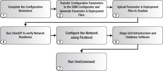
Figure 8-1. The configuration process
As indicated in Figure 8-1, the first step in the process is to fill out the configuration worksheet included in the Exadata documentation set. The purpose of this worksheet is to aid you in gathering all the information you will need to configure your system. When filling in the networking components of the worksheet you will need to enlist the help of your network administrator to reserve IP addresses and register new network names with the domain name server. It's important to understand how these configuration settings are used, so we'll spend a substantial amount of time discussing them in “Step 1: The Configuration Worksheet.”
Once you have completed the configuration worksheet, you will transfer that information to the DBM Configurator (dbm_configurator.xls). This is an Excel spreadsheet that generates all the parameter and deployment files OneCommand needs for configuring your system. In addition to parameter and deployment files, the DBM Configurator generates the checkip.sh script you should use to verify your network settings. This script validates the format of the IP addresses you entered, checks to see if any of them are already in use, and verifies that the network names you specified can be resolved by your DNS server. Once this is done, you are ready to upload these files to Exadata.
Before running OneCommand, you will need to stage the installation media for the Grid Infrastructure and the database (including any Oracle-prescribed patches). The final step of the process is to execute OneCommand. Its operation consists of multiple steps that configure all the components of your Exadata Database Machine. The top-level script that runs OneCommand is called deploy112.sh (112 presumably stands for 11gR2). This script can be run end-to-end, executing all of the steps automatically, or you may specify a step to run using command-line options. We strongly recommend running these steps one at a time. Doing so makes it much easier to troubleshoot if a step fails to complete successfully.
![]() Note: Rather than create an Exadata-specific release of their Grid Infrastructure, ASM, and RDBMS products, Oracle chose to integrate the Exadata specific code right into the same 11gR2 product you would install on non-Exadata platforms. When they did this, Oracle provided a mechanism for releasing Exadata-specific patches that could be managed separately from the mainstream product and coined a new term, bundle patches. Bundle patches are Oracle's way of tracking and distributing fixes for their storage cell software as well as Exadata-specific fixes for the Grid Infrastructure, ASM, and database software.
Note: Rather than create an Exadata-specific release of their Grid Infrastructure, ASM, and RDBMS products, Oracle chose to integrate the Exadata specific code right into the same 11gR2 product you would install on non-Exadata platforms. When they did this, Oracle provided a mechanism for releasing Exadata-specific patches that could be managed separately from the mainstream product and coined a new term, bundle patches. Bundle patches are Oracle's way of tracking and distributing fixes for their storage cell software as well as Exadata-specific fixes for the Grid Infrastructure, ASM, and database software.
When you take delivery of your Exadata Database Machine, certain tasks will he completed by an Oracle hardware technician. These tasks include connecting all the networked components inside the Exadata rack and configuring IP addresses for the private network (IB switch). When this process is complete, all compute nodes and storage cells will be connected together through the IB switch. OneCommand is only run from the first compute node and uses the private network to execute configuration commands on other servers and storage cells, as well as to install the Grid Infrastructure and RDBMS software on all database servers. There is no place in the configuration worksheet or the DBM Configurator to specify the network address, and the default is 192.168.10. If this network address is already in use elsewhere in your network infrastructure, this may create routing problems later. Be sure to mention this to your Oracle delivery coordinator early in the process so they can negotiate an appropriate network address for your InfiniBand network.
Configuring Exadata
The first step in configuring Exadata is generally to work through the configuration worksheet. If you are comfortable with the process, you can opt out of step 1 and enter your parameters directly into the DBM Configurator as you gather them. But don't underestimate the value of the configuration worksheet. It is an integral part of the process Oracle uses; and for good reason. Even experienced Exadata technicians continue to use the configuration worksheet. It is a good communication tool and helps to ensure that the installation goes smoothly.
Step 1: The Configuration Worksheet
The configuration worksheet is provided by Oracle as part of the Exadata documentation set. The documentation is not downloadable from any of the Oracle Web sites. Instead, it is installed in the /usr/share/doc/oracle/Exadata directory of the storage cells. Simply connect to one of the cells as root, celladmin, or cellmonitor and download it to your laptop. Open the welcome.html file in your Web browser and you will see a complete list of all the documents in HTML and PDF format. The one you are looking for is labeled Exadata Database Machine Configuration Worksheets. The worksheet is fairly well documented, but we'll go through it here and talk a little more about some of the parameters and settings you will need to provide. The information collected in the worksheet falls into four general categories:
- Exadata configuration parameters
- Oracle environment parameters
- Network settings
- Cell alert notification parameters
We'll be following a slightly different format here, but we'll discuss all of the configuration settings and parameters from the Oracle documentation and adding some commentary along the way.
Exadata Configuration Parameters
Exadata configuration parameters are system-wide settings, some of which are used for generating yet other parameters used in the configuration process. For example, the Exadata Database Machine Name you provide in the worksheet is used as a host name prefix for all network host names in your Exadata system, including compute nodes, storage cells, network switches, ILOMs, and the KVM. It is also used as a prefix for the cluster name and SCAN name required by Grid Infrastructure.
![]() Note: We recently noticed that the new version of the DBM Configurator now appends the Exadata Database Machine Name to the ASM disk group names. For example, if the machine name is ‘
Note: We recently noticed that the new version of the DBM Configurator now appends the Exadata Database Machine Name to the ASM disk group names. For example, if the machine name is ‘exa,' then the Configurator generates a disk group name of DATA_EXA, rather than DATA_DG, for the data disk group. This is the default behavior, but it may be overridden before generating your configuration files. We'll talk more about naming your ASM disk groups in “Step 2: The DBM Configurator.” You may notice that some of the other chapters of this book, Chapter 15, for example, use the old naming convention.
Table 8-1 shows the Exadata configuration parameters you will enter in the configuration worksheet.
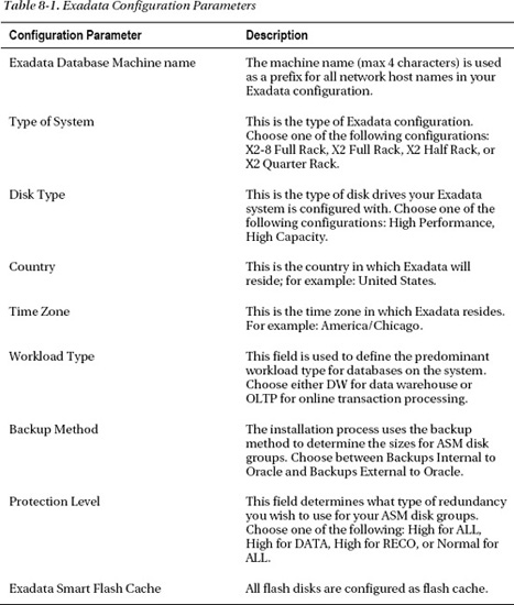
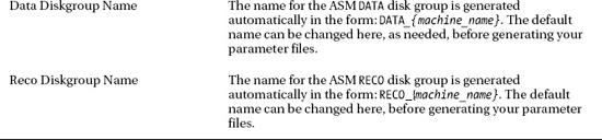
Some of the parameters, like Country and Time Zone, are pretty standard fare when configuring servers. Other parameters are Exadata-specific and will be new to you. One thing you may notice right away is that there is no way to name your ASM disk groups in the configuration worksheet. If you don't like the default names of DATA_{machine_name} and RECO_{machine_name}, you will have the opportunity to change them later in the DBM Configurator. The Exadata configuration parameters are described as follows:
Exadata Database Machine Name: This parameter can be 1–4 characters in length and is used to generate network host names for network endpoints in your Exadata frame. It is also used to name the RAC cluster and the Simple Client Access Name (SCAN) required by RAC. For example, a machine name of
exaproduces a cluster name of ‘exa_cluster'and a SCAN name ofexa-scan.ourcompany.com. This parameter is case-sensitive for all but the disk group name postfix, if any, in which case it is forced to uppercase. The following listing shows the management network host names generated for the database servers and storage cells in a quarter rack configuration. In step 2, we'll take a look at a complete listing of the names prefixed with the machine name for a quarter rack configuration.# Management Network
exadb01.ourcompany.com exadb01
exadb02.ourcompany.com exadb02
exacel01.ourcompany.com exacel01
exacel02.ourcompany.com exacel02
exacel03.ourcompany.com exacel03If there is a chance you will ever have more than one Exadata system in your data center, consider enumerating your machine name to provide uniqueness. For example a machine name of
exa1allows for future systems to be namedexa2,exa3, and so on.Type of System: The type of system determines how many compute nodes and storage cells are in your configuration. This field is presented as a drop-down list, illustrated in Figure 8-2.

Figure 8-2. The Type of System drop-down
This parameter is used to determine how many compute nodes and storage cells your system has when generating IP addresses and host names. We'll talk more about this later, in the “Network Settings” section, but OneCommand generates sequential IP addresses by starting with a base address for the first host and then incrementing from that address for each host. For example, if your management IPs start at 192.168.8.201, then the following IP addresses will be generated for the compute nodes and storage cells in a quarter rack.
192.168.8.201
exadb01.ourcompany.com192.168.8.202
exadb02.ourcompany.com192.168.8.203
exacel01.ourcompany.com192.168.8.204
exacel02.ourcompany.com192.168.8.205
exacel03.ourcompany.com
![]() Note: The way OneCommand assigns IP addresses sequentially from a base address can be problematic when adding compute nodes and storage cells to your configuration. We'll talk more about this later in the chapter when we look at upgrading Exadata.
Note: The way OneCommand assigns IP addresses sequentially from a base address can be problematic when adding compute nodes and storage cells to your configuration. We'll talk more about this later in the chapter when we look at upgrading Exadata.
Disk Type: This field is presented as a drop-down list. Exadata X2 models come in two flavors, High Capacity Disks and High Performance Disks. High-capacity disks have a capacity of 2 terabytes, while high performance disks have a capacity of 600 gigabytes. This information is used to calculate cell disk and grid disk sizes for the installation.
Workload Type: Several settings from the configuration worksheet are used to create a starter database during the installation process. These parameters are used to create a database template that is in turn used by the Database Configuration Assistant (
dbca) at the end of the installation process. The workload type you specify determines whether your default database is optimized for OLTP or DW workloads. Instance parameters such asSGA_TARGETandPGA_TARGETare sized based on the Workload Type you specified for your database.Backup Method: This setting determines how your disk groups are sized during the installation process. Disk space is allocated to the
DATAandRECOdisk groups as follows:Backups Internal to Exadata: If you plan to use the Fast Recovery Area (FRA) to store online database backups, choose Backups Internal to Oracle. When this allocation scheme is selected, disk space for the
DATAandRECOdisk groups will be allocated as follows:
DATA: 40%
RECO: 60%Backups External to Exadata: If you are planning to back up your databases directly to tape, NFS, or some other storage external to Exadata, choose Backups External to Exadata. When this allocation scheme is chosen, disk space will be allocated to the
DATAandRECOdisk groups as follows:
DATA: 80%
RECO: 20%Protection Level: This determines what level of redundancy will be configured for your ASM disk groups,
DATAandRECO. Similar to the Type of System field, this field is presented as a drop-down list from which you can choose the redundancy for your disk groups. Keep in mind that normal redundancy halves the usable space in your disk groups. Normal redundancy is the minimum allowable redundancy level. High redundancy provides the best protection from disk and storage cell failures, but it does so at the cost of reducing available space by two thirds. The following combinations are supported:High For All: This configuration can significantly reduce available space in your disk groups. According to Oracle, it is best used when the backup method chosen is Backups External to Oracle.
High For DATA: In this configuration, ASM redundancy is set to high for
DATA, whileRECOis set to normal redundancy. This is best suited for systems that back up the databases to external storage, such as tape, VTL, NFS, and so on.High For RECO: In this configuration, high redundancy is used for
RECOand normal redundancy is used for theDATAdisk group. This configuration is best suited for databases that back up to the FRA.Normal For ALL: This configuration uses normal redundancy for all disk groups. While it provides quite a bit more usable space in the disk groups, keep in mind that the simultaneous loss of one disk drive from two storage cells will cause ASM to dismount your disk groups. If that happens, your databases using those disk groups will also be offline.
As you consider which protection scheme is right for you, think about your pain tolerance where it comes to system outages. Normal redundancy provides more storage and less protection from disk/cell failures. Unless you can afford for your databases to be down for an extended period of time, you should lean toward high redundancy for the
DATAdisk group. If you can afford an outage while transient disk/cell failures are resolved, or in a worst-case scenario, wait for a full database recovery, then perhaps high redundancy for theRECOdisk group is a better fit. If space is very tight and you can tolerate these types of outages, then you may consider setting redundancy for all disk groups to normal.The redundancy level for your
SYSTEM_DG(orDBFS_DG) disk group, which stores the OCR and Voting files, will be automatically set to the maximum level supported by your Exadata rack configuration. High redundancy is not supported on quarter rack configurations, so normal redundancy is the best you can do for them. For half rack and full rack configurations, redundancy will always be set to high for theSYSTEM_DGdisk group.
![]() Kevin Says: Protection level is a very sensitive and seemingly politically charged topic. The manner in which ASM chooses partner disks leaves any normal redundancy disk group at much greater risk of data loss from a double-disk failure than would be the case with traditional RAID-style protection. While there may be hundreds of disks that could fail simultaneously in a double disk failure, it's just a matter of (bad) luck which ones fail. If the “wrong two disks” in a normal redundancy situation happen to fail, the administrator will have to deal with data loss. For this reason, the authors are correct to point out which high-redundancy scheme is recommended based on the backup strategy protecting the system.
Kevin Says: Protection level is a very sensitive and seemingly politically charged topic. The manner in which ASM chooses partner disks leaves any normal redundancy disk group at much greater risk of data loss from a double-disk failure than would be the case with traditional RAID-style protection. While there may be hundreds of disks that could fail simultaneously in a double disk failure, it's just a matter of (bad) luck which ones fail. If the “wrong two disks” in a normal redundancy situation happen to fail, the administrator will have to deal with data loss. For this reason, the authors are correct to point out which high-redundancy scheme is recommended based on the backup strategy protecting the system.
The topic of ASM normal redundancy protection from double disk failure scenarios is not Exadata-specific. However, until the advent of Exadata, customers rarely trusted their data to ASM protection—opting instead for external redundancy.
Exadata Smart Flash Cache: There is no mention of the flash cache in the configuration worksheet but there is in the DBM Configurator.
Oracle Environment Parameters
The next set of parameters is used to define the O/S user and group accounts, as well as the location for the Grid Infrastructure (Clusterware) and database software installation. These parameters are well known to DBAs who have been through an Oracle RAC 11gR2 installation or two. Table 8-2 shows the parameters you will need to provide. The parameters in italics cannot be modified in the configuration worksheet and are included for informational purposes only. Some of them, however, can be changed when you fill out the DBM Configurator later.


The InfiniBand private network is more commonly known to DBAs as the private Interconnect. This field shows starting IP address for the range of IPs the RAC cluster will use for cluster Interconnect traffic (heartbeat, cache fusion, and so on). If for some reason you have changed the IP addresses for the IB network you will need to also make that adjustment in the DBM Configurator when you transfer the worksheet parameters later.
![]() Note: OneCommand does not allow you to modify the character set parameters. So the default database created will use the AL32UTF8 database character set, and AL16UTF16 national character set. After the installation is complete, you may choose to drop the default database and create your own databases that meet the specific requirements of your environment. Keep in mind that Oracle recommends using Unicode for all new database implementations.
Note: OneCommand does not allow you to modify the character set parameters. So the default database created will use the AL32UTF8 database character set, and AL16UTF16 national character set. After the installation is complete, you may choose to drop the default database and create your own databases that meet the specific requirements of your environment. Keep in mind that Oracle recommends using Unicode for all new database implementations.
Network Settings
The final set of configuration parameters is where you specify the network settings for Exadata. OneCommand supports the configuration of up to four networks, identified as NET0 through NET3. NET0 and NET1 are required and are used for the management network and client access network, respectively. NET2 and NET3 are optional networks you may choose to configure if needed. Table 8-3 shows all the network settings used to configure Exadata.
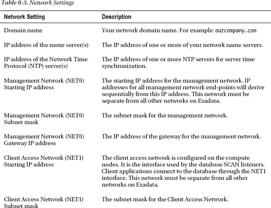
The domain name, DNS server, and NTP server settings are all standard network settings. These should be specified as you would for any other Oracle database server on your network. The remaining network settings are described as follows:
Management Network (NET0): The management network is used for administrative access to the database servers and storage cells. You can think of this network as your SSH entry point for logging into the compute nodes, storage cells, and IB switches. The management network is serviced by the internal Cisco network switch. Only one network drop is required to uplink the Cisco management switch to your company network. The management network also includes the ILOM interfaces on the compute nodes and storage cells.
Client Access Network (NET1): The client access network provides SQL*Net access to the database. This is the network used by the SCAN Listeners to establish client connections to the database. Only the database servers use this network; storage cells are not assigned an IP address on this network. And even though the database servers have an IP on this network, you cannot connect to these IP addresses using SSH, because SSH is not configured to listen on this network. One network drop (minimum) is required for each database server to provide access through your company network. If channel bonding is used to provide hardware redundancy, you will need two drops per database server. The cable pairs from the database servers should be connected to redundant network switches to provide full network redundancy. If channel bonding is configured for the client access network, OneCommand configures these devices in the
ifcfg-eth1andifcfg-eth2configuration files in the/etc/sysconfig/network-scriptsdirectory. They are bonded to thebondeth0device defined in theifcfg-bondeth0file. For example, the following listing shows how the master bond device is referenced by theeth1andeth2slave devices.# egrep 'DEVICE|MASTER|SLAVE' ifcfg-bondeth0 ifcfg-eth1 ifcfg-eth2
ifcfg-bondeth0:DEVICE=bondeth0
ifcfg-eth1:DEVICE=eth1
ifcfg-eth1:MASTER=bondeth0
ifcfg-eth1:SLAVE=yes
ifcfg-eth2:DEVICE=eth2
ifcfg-eth2:MASTER=bondeth0
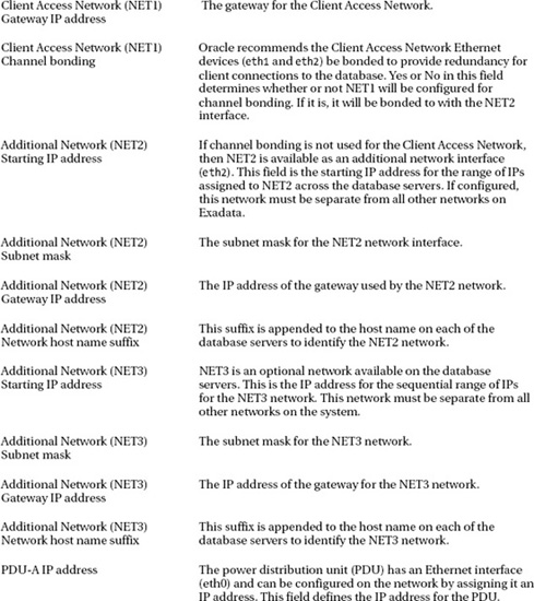
ifcfg-eth2:SLAVE=yesChannel Bonding (NET1): Oracle recommends that you configure NIC bonding for the client access network to provide network redundancy. If you choose to bond the client access network, OneCommand will use NET2 as the secondary network device.
Additional Network (NET2): If channel bonding is not configured for the client access network, NET2 is may be used to configure an additional network.
Additional Network (NET3): The NET3 device is available as an additional network if needed.
![]() Tip: In addition to the network devices we've discussed here, each Exadata X2-2 compute node features two 10 gigabit Ethernet (10gE) network ports. These ports are not ready to be used right out of the box. You must first purchase and install SFP transceiver modules in order to connect them to your network switch. Each Exadata X2-8 compute node has eight of these 10gE ports. If your backup media server supports 10gE, then this network could be used to improve the performance of your database backups.
Tip: In addition to the network devices we've discussed here, each Exadata X2-2 compute node features two 10 gigabit Ethernet (10gE) network ports. These ports are not ready to be used right out of the box. You must first purchase and install SFP transceiver modules in order to connect them to your network switch. Each Exadata X2-8 compute node has eight of these 10gE ports. If your backup media server supports 10gE, then this network could be used to improve the performance of your database backups.
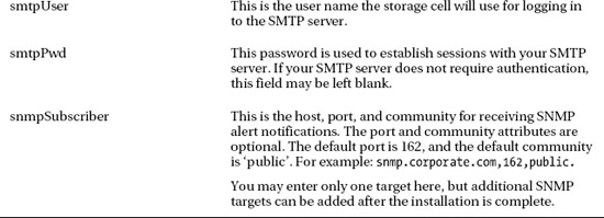
Cell Alert Notification Parameters
The cellsrv management service (on each storage cell) monitors the health of the storage cells and is capable of sending out SMTP and SNMP notifications if problems arise. Configuring email and SNMP alert notifications for the storage cells is optional but highly recommended. Table 8-4 describes the various parameters used to configure Cell Alert Notifications.

Step 2: The DBM Configurator
Once you've completed the configuration worksheet, the information you gathered can be transferred to the DBM (Database Machine) Configurator. The DBM Configurator is an Excel spreadsheet (dbm_configurator.xls) that generates all the input files OneCommand will need to carry out the installation process. The spreadsheet is located in the /opt/oracle.SupportTools/onecommand directory on every compute node. The DBM Configurator is heavily documented in the Exadata Database Machine Owner's Guide, so we won't be discussing all of the fields here. But we will take a look at how a few of them are used in the installation process. Table 8-5 describes a few of the key data-entry fields from the spreadsheet.

The DBM Configurator process is as follows:
- Enter the configuration parameters from the configuration worksheet into the DBM Configurator.
- Click the Generate button on the right side of the spreadsheet. A brief report showing the topology of your system is generated at the bottom of the spreadsheet. Scroll down to review your settings and make corrections to the output as needed. When you are finished making changes, you are ready to create the output files.
- The last step is to click the Create Config Files button. This generates the parameter and deployment files used by OneCommand. It also creates an installation template in a separate spreadsheet tab in the Configurator. The information in the template consists mostly of the input parameters you provided in an easy-to-read format. Review the template carefully and make changes in the data entry or topology report areas as needed. If you must go back and make any changes, you should click the Generate and Create Config Files buttons again so that your changes are written to the output files.
![]() Caution: Be careful when filling out the spreadsheet. It's very easy for a typo to slip through and cause you problems later. The topology report generated below the data entry fields is useful for catching errors in the host names and IP addresses you entered. This report is created when you click the Generate button.
Caution: Be careful when filling out the spreadsheet. It's very easy for a typo to slip through and cause you problems later. The topology report generated below the data entry fields is useful for catching errors in the host names and IP addresses you entered. This report is created when you click the Generate button.
Step 3: Upload Parameter and Deployment Files
The DBM Configurator generates a number of files that will be used to configure your Exadata Database Machine. These files are saved in the C:dbmachine_{company_name}{machine_name} directory. The files are primarily used by OneCommand to perform the installation and configuration process. But a few of the files are used by other processes. For example, the checkip.sh script uses the dbm.dat file to perform network readiness tests prior to running OneCommand. These files will be needed for various tasks going forward in the configuration, and they must be uploaded to the first compute node on your Exadata platform.
There are a couple of ways to transfer the parameter and deployment files to Exadata. One method involves setting up temporary network access to the first compute node. This network configuration will be replaced with permanent network settings by Firstboot or ApplyConfig in subsequent steps. The other option is to save the files to a portable USB flash drive and then, using the USB port on the front panel of the first compute node, copy the files to the OneCommand directory. We'll talk about where that directory is in the following example. The USB approach is as follows:
- Connect the USB flash drive to your laptop and copy the directory containing your configuration files to the USB drive. For example:
mkdir e:exa

copy C:dbmachine_OurCompanyexa e:exa


C:> copy dbmachine_OurCompanyexa e:exa

dbmachine_OurCompanyexaall_group

dbmachine_OurCompanyexaall_ib_group

dbmachine_OurCompanyexaall_nodelist_group

dbmachine_OurCompanyexacell_group

dbmachine_OurCompanyexacell_ib_group

dbmachine_OurCompanyexacheckip.sh

dbmachine_OurCompanyexaconfig.dat

dbmachine_OurCompanyexadatabasemachine.xml

dbmachine_OurCompanyexadbm.dat

dbmachine_OurCompanyexadbmachine.params

dbmachine_OurCompanyexadbMachine_exa

dbmachine_OurCompanyexadbs_group

dbmachine_OurCompanyexadbs_ib_group

dbmachine_OurCompanyexahosts.sample

dbmachine_OurCompanyexapreconf-11-2-1-1-0.csv

dbmachine_OurCompanyexapreconf-11-2-1-2-2.csv

dbmachine_OurCompanyexapreconf-11-2-2-1-0.csv

dbmachine_OurCompanyexapreconf.csv

dbmachine_OurCompanyexapriv_ib_group

19 file(s) copied. - Remove the USB flash drive from your laptop and connect it to the USB port on the front panel of the first compute node in your system. The servers are numbered from bottom to top in the rack, so the bottom-most compute node is the one you are looking for.
- Using the Exadata KVM, log in to the first compute node as root and check the
/var/log/dmesgfile to determine the device name assigned to the USB flash drive. For example, you should see a message something like the following:… Attached scsi removable disk sdbYou can confirm the partition and device name using the
fdiskcommand as follows: - Create a directory you can use as a mount point for the USB flash drive. For example,
/mnt/usb. - Mount the USB device using the following command.
# mount -t vfat /dev/sdb1 /mnt/usb - Copy the files to the
onecommanddirectory as follows:# cp /mnt/sdb1/exa/* /opt/oracle.SupportTools/onecommand - Unmount the USB flash drive as follows:
# umount /mnt/usb - You can now remove the USB flash drive from the compute node.
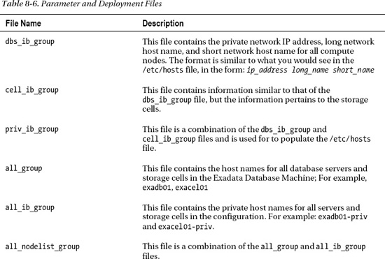
Table 8-6 describes what these files are and how they are used in the installation and configuration process.

In addition to the files listed in this table, OneCommand also creates a database template (dbmDBTemplate) used for creating your starter database. The template contains database parameters that should be used whenever creating databases on Exadata, such as these:
_file_size_increase_increment

_kill_diagnostics_timeout

_lm_rcvr_hang_allow_time
The template file, dbmDBTemplate.dbt, is installed in the $ORACLE_HOME/assistants/dbca/templates directory during the OneCommand installation process.
Step 4: CheckIP (checkip.sh)
One of the files the DBM Configurator generates is a shell script used to validate your network settings. The checkip.sh (CheckIP) script reads your network configuration settings from its parameter file (dbm.dat, also generated by the Configurator) and runs a variety of tests to verify network readiness before, during, and after the configuration process. CheckIP tests the network to confirm that the following conditions are met:
- IP addresses that should respond to a ping, do.
- IP addresses that should not respond to a ping, do not.
- Host names that must be registered in DNS can be both forward and reverse resolved using the first DNS server specified in the
dbm.datfile.
Before running OneCommand, the checkip.sh script (CheckIP) should be run to validate the readiness of your corporate network. The script has several modes of operation that validate your network configuration at various points of the configuration process. At this point, you should run CheckIP in pre_applyconfig mode from a server, external to Exadata platform. The server you choose to run CheckIP from must have the same network visibility as your Exadata system will have. For example, the server must have access to the same DNS server and NTP server, and it must be able to ping the IP addresses you listed in your network settings for Exadata. Ideally, the server you choose should run the Linux operating system, but Unix servers may work as well. CheckIP uses the Bash shell, which is popular on the Linux platform but also available on most versions of Unix. The O/S commands required by CheckIP include host, ping, ntpdate, tr, cut, sed, wc, grep, and head. Be aware that even if these commands are available on your Unix server, they may produce incompatible output and cause false failures in the output. The checkip.sh script and the dbm.dat parameter file are created in Linux/Unix format, so when you upload them from your laptop, be sure to transfer them in binary mode. If you want to be sure, you can use the dos2unix command after uploading them to ensure that the format is correct before executing the script. Upload the checkip.sh and dbm.dat files to a server on your network and run the following command as the root user:
./checkip.sh -m pre_applyconfig
CheckIP will print its progress out to the screen as well as build a dbm.out report file. The following listing shows sample output from the CheckIP script:
Running in mode pre_applyconfig

Using name server 192.168.10.15 found in dbm.dat for all DNS lookups

Processing section #

Processing section

Processing section DOMAIN
ourcompany.com

…

Processing section GATEWAY

GOOD : 10.34.96.1 pings successfully

GOOD : 10.34.97.1 pings successfully

GOOD : 10.34.97.1 pings successfully

GOOD : 10.34.98.1 pings successfully


Processing section SCAN

GOOD : exa-scan.ourcompany.com resolves to 3 IP addresses

GOOD : exa-scan.ourcompany.com forward resolves to 10.34.97.36

GOOD : 10.34.97.36 reverse resolves to ex01-scan.ourcompany.com.

GOOD : 10.34.97.36 does not ping

GOOD : exa-scan.your.ourcompany.com forward resolves to 10.34.97.37

GOOD : 10.34.97.37 reverse resolves to ex01-scan.ourcompany.com.

GOOD : 10.34.97.37 does not ping

GOOD : exa-scan.ourcompany.com forward resolves to 10.34.97.38

GOOD : 10.34.97.38 reverse resolves to ex01-scan.ourcompany.com.

GOOD : 10.34.97.38 does not ping


…

Processing section COMPUTE

GOOD : exadb01.ourcompany.com forward resolves to 10.34.96.20

GOOD : 10.34.96.20 reverse resolves to exadb01.ourcompany.com.

GOOD : 10.34.96.20 does not ping

GOOD : exadb02.ourcompany.com forward resolves to 10.34.96.21

GOOD : 10.34.96.21 reverse resolves to exadb02.ourcompany.com.

GOOD : 10.34.96.21 does not ping


…

Processing section CELL

GOOD : exacel01.ourcompany.com forward resolves to 10.34.96.28

GOOD : 10.34.96.28 reverse resolves to exacel01.ourcompany.com.

GOOD : 10.34.96.28 does not ping

GOOD : exacel02.ourcompany.com forward resolves to 10.34.96.29

GOOD : 10.34.96.29 reverse resolves to exacel02.ourcompany.com.

GOOD : 10.34.96.29 does not ping


…

Processing section SWITCH

…

Processing section VIP

…

Processing section NET3

…

Processing section SMTP
The output report generated in the dbm.out file contains the same information as we see in the display. If any validation errors occur, they are prefixed with ERROR,' and a message describing the failure indicates the problem encountered, and what the expected results should be. For example:
Processing section SCAN

GOOD : exa-scan.ourcompany.com resolves to 3 IP addresses

ERROR : exa-scan. ourcompany.com forward resolves incorrectly to 144.77.43.182 144.77.43.181 144.77.43.180 , expected 144.77.43.87

…

Processing section COMPUTE

GOOD : exadb01.ourcompany.com forward resolves to 10.80.23.1

GOOD : 10.80.23.1 reverse resolves to exadb01.ourcompany.com.

ERROR : 10.80.23.1 pings
The output from CheckIP must contain no errors. If you see any errors in the output, they must be corrected before running OneCommand. Check the dbm.dat file and make sure you didn't enter an IP address incorrectly, or mistype a hostname before opening a discussion with your network administrator. Sometimes a simple correction to a data entry field on the DBM Configurator is all that is needed. If everything looks in order from your side, then send the dbm.out file to your network administrator for remediation.
Step 5: Firstboot
When the Oracle hardware engineers complete their installation, you are ready to boot up the compute nodes and storage cells for the first time. When you are ready to begin configuring Exadata, open up the internal KVM and power up one compute node or storage cell at a time. It's not important which order you follow. The Firstboot process is not documented in the Oracle manuals, so we'll take a minute to talk through the boot process and what happens the first time you boot the servers and storage cells.
Every time a server boots up, the /etc/init.d/precel script is called at run level 3. This script calls the /opt/oracle.cellos/cellFirstboot.sh (Firstboot) script. Firstboot determines whether or not the network settings have been configured. This is undocumented, but it appears that it is triggered by the existence of the /opt/oracle.cellos/cell.conf file. This file is created and maintained by the /opt/oracle.cellos/ipconf.pl script (IPConf) and contains all the information about your network configuration. If the file exists, it is assumed that the system is already configured and the boot cycle continues. But if the file is not found, Firstboot calls IPConf and you are lead, interactively, through the network configuration process. IPConf is used to set the following network settings for your compute nodes and storage cells:
- Name Server (DNS)
- Time Server (NTP)
- Country Code
- Local Time Zone
- Hostname
- IP address, netmask, gateway, type, and hostname for all network devices. The type is required and used for internal documentation in the
cell.conffile. Valid types are Private, Management, SCAN, and Other.
For example, the following listing shows the prompts for configuring the management network:
Select interface name to configure or press Enter to continue: eth0

Selected interface. eth0

IP address or none: 192.168.8.217

Netmask: 255.255.252.0

Gateway (IP address or none) or none: 192.168.10.1


Select network type for interface from the list below

1: Management

2: SCAN

3: Other

Network type: 1

Fully qualified hostname or none: exadb03.ourcompany.com
When you have finished entering all your network settings, IPConf generates a new cell.conf file and reboots the system. Once the system has finished rebooting, it is ready for the O/S configuration and software installation performed by OneCommand.
ApplyConfig
For quarter rack and half rack configurations, it's a fairly trivial task to enter all your network settings using the Firstboot process. For full rack configurations, however,it can be a time-consuming and error-prone process. The applyconfig.sh script (ApplyConfig) automates the process. ApplyConfig is found in the /opt/oracle.SupportTools/firstconf directory of all compute nodes and storage cells. It is basically a wrapper script for the IPConf script we discussed earlier, for Firstboot). In step 3, we discussed the various parameter and deployment files generated by the DBM Configurator. Among these files was the preconf.csv parameter file, (see also preconf-11-2-1-1-0.csv, preconf-11-2-1-2-2.csv, and preconf-11-2-2-1-0.csv). The preconf.csv file contains all the network settings IPConf needs to create a cell.conf file for each compute node and storage cell.
IPConf may be run interactively (as we saw in the Firstboot example), allowing you to enter your network settings manually. IPConf may also be run non-interactively, taking its input from the preconf.csv parameter file. When run in this mode, IPConf creates a full set of cell.conf files, one for each compute node and storage cell. For example, the following command creates all the required cell.conf files for an Exadata half rack configuration:
[root@exadb01 root]# cd /opt/oracle.SupportTools/firstconf

[root@exadb01 firstconf]# /opt/oracle.cellos/ipconf

  –preconf /opt/oracle.SupportTools/onecommand/{company_name}/preconf.csv

  -generateall

  -generateorder /opt/oracle.SupportTools/firstconf/half
That last parameter (half) is a reference to a parameter file containing the factory default private IP address for all compute nodes and storage cells in an Exadata half rack configuration. The files generated by IPConf are saved in the /tmp/ipconf directory as follows:
[root@exadb01 firstconf]# ls -1 /tmp/ipconf

cell.conf.exacel01.ourcompany.com

cell.conf.exacel02.ourcompany.com

cell.conf.exacel03.ourcompany.com

cell.conf.exacel04.ourcompany.com

cell.conf.exacel05.ourcompany.com
cell.conf.exacel06.ourcompany.com

cell.conf.exacel07.ourcompany.com

cell.conf.exadb01.ourcompany.com

cell.conf.exadb02.ourcompany.com

cell.conf.exadb03.ourcompany.com

cell.conf.exadb04.ourcompany.com
ApplyConfig calls IPConf to generate these files and installs them as /opt/oracle.cellos/cell.conf in each compute node and storage cell. To run ApplyConfig, log in as root to the first compute node in your system and run applyconfig.sh as follows:
[root@exadb01 root]# cd /opt/oracle.SupportTools/firstconf

[root@exadb01 firstconf]# ./applyconfig.sh half

  /opt/oracle.SupportTools/onecommand/preconf.csv
Once the cell.conf files have been installed on all servers, ApplyConfig uses the dcli command to run the cleanup_n_reboot.sh script on all servers. As the name implies, this script performs cleanup tasks and reboots the servers. Once the servers complete the boot cycle, Exadata should be ready to be configured using OneCommand.
Whether you choose to configure the Exadata network components manually, using Firstboot, or by running ApplyConfig, you should verify the network configuration once again before proceeding with the installation process. Run the CheckIP post_applyconfig process to verify your configuration as follows:
# cd /opt/oracle.SupportTools/onecommand

[root@exadb03 onecommand]# ./checkip.sh -m post_applyconfig


Exadata Database Machine Network Verification version 1.9

Network verification mode post_applyconfig starting ...

Saving output file from previous run as dbm.out_8385

Using name server 192.168.10.19 found in dbm.dat for all DNS lookups

Processing section DOMAIN  : SUCCESS

Processing section NAME    : SUCCESS

Processing section NTP     : SUCCESS

Processing section GATEWAY : SUCCESS

Processing section SCAN    : SUCCESS

Processing section COMPUTE : SUCCESS

Processing section CELL    : SUCCESS

Processing section ILOM    : SUCCESS

Processing section SWITCH  : SUCCESS

Processing section VIP     : SUCCESS

Processing section SMTP    : SMTP "Email Server Settings" mail.ourcompany.com 25:0 SUCCESS
Again, the output from all tests must be SUCCESS before continuing with the installation. If errors occur, you can review the dbm.out file for the reason of the failure.
Step 6: Staging the Installation Media
The last step before running OneCommand is to make sure you have the necessary Oracle install media properly staged on the first compute node. OneCommand will handle unzipping the installation files to a working directory and perform the entire installation automatically. My Oracle Support (MOS) note 888828.1 contains a complete list of Oracle software and patches supported for the Exadata Database Machine. However, the version of OneCommand that came with your Exadata system only supports automatic installation of certain software versions and patches.
The Exadata Owner's Guide that came with your system specifies the RDBMS and Grid Infrastructure installation media OneCommand needs for the installation. The patches and install media required by OneCommand tends to change as new versions of OneCommand are released. Currently, the following media is required by OneCommand:
- Oracle RDBMS & Grid Infrastructure 11.2.0.2 (patch 10098816)
p10098816_112020_Linux-x86-64_1of7.zipp10098816_112020_Linux-x86-64_2of7.zipp10098816_112020_Linux-x86-64_3of7.zip
The Readme file included within the onecommand directory states which bundle patches are supported by the version of OneCommand installed on your system. For example, we recently installed a quarter rack X2-2 system in our lab. The following listing shows the patches supported by it in the Readme file:
# egrep 'PATCHES|bundle patch' /opt/oracle.SupportTools/onecommand/README

PATCHES Applied with this version

Bug 10252487 - 11.2.0.2 db machine bundle patch 1
Checking MOS note 888828.1, we see that Bundle Patch 1 for 11.2.0.2 is patch 10252487.
- Bundle Patch 1 (patch 10252487)
- p10252487_112020_Linux-x86-64.zip
The install media (zip files) listed above may already be installed on the first compute node of your Exadata Database Machine. So it's worth a look, and it may save you some time to check before downloading the installation files. If necessary, download and stage the installation files in the /opt/oracle.SupportTools/onecommand directory on the first compute node.
Step 7: Running OneCommand
Although Exadata can be configured manually, OneCommand is the preferred method. OneCommand is an Oracle-provided utility consisting of several configuration steps, (31 as of this writing). OneCommand provides two very important benefits to Exadata customers and Oracle's support staff. First, it creates a limited number of standardized (and well known) configurations, which makes the platform much easier to support. After all, who wants to hear “oh, I've never seen it configured that way before” when we finally get a support tech on the phone? This is one of Exadata's key strengths. Second, it provides a simplified and structured mechanism for configuring Exadata from start to finish. This means that with very little knowledge of Exadata internals, an experienced technician can install and configure Exadata in a matter of hours. It's unclear whether Oracle originally intended to provide support for OneCommand externally, but about the same time the X2 began shipping, Oracle added it to the Exadata Owner's Guide. The instructions in the Owner's Guide are not very extensive, but the Readme included with the utility does a fairly good job of explaining how to run it, and what to watch out for. OneCommand comes preinstalled in the /opt/oracle.SupportTools/onecommand directory on your compute nodes. If you need access to the latest version of OneCommand, it is available for download from Oracle's Technology Network. The download link is password-protected however, and you will need to open a service request with Oracle Support to request temporary access to download it.
OneCommand is a multiple-step process that is run from a shell script called deploy112.sh. These steps can be run end-to-end or one at a time. Table 8-7 shows each step in the OneCommand process along with a brief description of what the step does.


The main script used to run OneCommand is deploy112.sh (Deploy112). The 31 installation steps may be listed by running Deploy112 as follows:
[root@exadb01 onecommand]# ./deploy112.sh -i –l

The steps in order are...

Step 0 =  ValidateThisNodeSetup

Step 1 =  SetupSSHForRoot

Step 2 =  ValidateAllNodes

Step 3 =  UnzipFiles

Step 4 =  UpdateEtcHosts

Step 5 =  CreateCellipnitora

Step 6 =  ValidateHW

Step 7 =  ValidateIB

Step 8 =  ValidateCell

Step 9 =  PingRdsCheck

Step 10 =  RunCalibrate

Step 11 =  ValidateTimeDate

Step 12 =  UpdateConfig

Step 13 =  CreateUserAccounts

Step 14 =  SetupSSHForUsers

Step 15 =  CreateOraHomes

Step 16 =  CreateGridDisks

Step 17 =  InstallGridSoftware

Step 18 =  RunGridRootScripts

Step 19 =  Install112DBSoftware

Step 20 =  Create112Listener

Step 21 =  RunAsmCa

Step 22 =  UnlockGIHome

Step 23 =  ApplyBP

Step 24 =  RelinkRDS

Step 25 =  LockUpGI

Step 26 =  SetupCellEmailAlerts

Step 27 =  RunDbca

Step 28 =  SetupEMDbControl

Step 29 =  ApplySecurityFixes

Step 30 =  ResecureMachine
![]() Note: OneCommand is constantly changing to improve the installation process and to support additional bundle patches. The number of steps and what they do is very likely to change with each version of Exadata. So be sure to review the README file for instructions on how to run OneCommand on your system before you begin.
Note: OneCommand is constantly changing to improve the installation process and to support additional bundle patches. The number of steps and what they do is very likely to change with each version of Exadata. So be sure to review the README file for instructions on how to run OneCommand on your system before you begin.
There are number of ways Deploy112 may be used. For example, the following command-line options process all 31 steps of the installation process, only stopping if a step failes:
[root@exadb01 onecommand]# ./deploy112.sh -i -r 0-30
Each step must complete successfully before you can proceed to the next. Oracle recommends running the steps one at a time, reviewing the output at the end of each before proceeding on to the next. Deploy112 provides this capability with the -s command line option. For example, the installation procedure would look something like the following:
[root@exadb01 onecommand]# ./deploy112.sh -i -s 0
Check output for errors…
[root@exadb01 onecommand]# ./deploy112.sh -i -s 1
Check output for errors…
[root@exadb01 onecommand]# ./deploy112.sh -i -s 2
Check output for errors…
[root@exadb01 onecommand]# ./deploy112.sh -i -s 3
and so on…
Deploy112 takes as input the parameters from the files you generated earlier using the DBM Configurator. Log files are created each time Deploy112 is called to execute a configuration step, and for some steps, it dynamically generates and executes a shell script that carries out all the tasks required. Reviewing these files can be very useful in determining why a step failed. The log files and dynamically generated shell scripts are stored in the onecommand/tmp directory.
The output generated by the various installation steps varies quite a bit. But in general, Deploy112 displays some header information telling you what step it is running, where to find the log file, and whether it completed successfully. For example, the following output was generated by running step 1 on the quarter rack system in our lab:
Script started, file is /opt/oracle.SupportTools/onecommand/tmp/STEP-1-exadb01-20110513110841.log

=========== 1 SetupSSHForRoot Begin ===============

Setting up ssh for root on ALL nodes....

Checking nodes in /opt/oracle.SupportTools/onecommand/all_group

......

INFO: We're running... /opt/oracle.SupportTools/onecommand/setssh-Linux.sh -s -c Y -h /opt/oracle.SupportTools/onecommand/all_group -p welcome1 -n N -x

...................................setssh-Linux.sh Done.

SUCCESS: Running SetSSH completed successfully...Return Status: 0 Step# 1

exadb01: Fri May 13 11:09:50 CDT 2011

exadb02: Fri May 13 11:09:50 CDT 2011
exadb03: Fri May 13 11:09:50 CDT 2011

exadb04: Fri May 13 11:09:50 CDT 2011

exacel01: Fri May 13 11:09:50 CDT 2011

exacel02: Fri May 13 11:09:50 CDT 2011

exacel03: Fri May 13 11:09:50 CDT 2011

exacel04: Fri May 13 11:09:50 CDT 2011

exacel05: Fri May 13 11:09:50 CDT 2011

exacel06: Fri May 13 11:09:50 CDT 2011

exacel07: Fri May 13 11:09:50 CDT 2011

SUCCESS: Running dcli completed successfully...Return Status: 0 Step# 1

INFO: Copying required files to all nodes...please wait...

INFO: Waiting for copies to complete...


INFO: Did SSH setup correctly...

Time spent in step 1 SetupSSHForRoot = 69 seconds

=========== 1 SetupSSHForRoot completed ===============

Running single step at a time....Exiting now

Exiting...

Script done, file is /opt/oracle.SupportTools/onecommand/tmp/STEP-1-exadb01-20110513110841.log
Upgrading Exadata
With all the companies out there adopting the Exadata platform, we expect hardware upgrades to be an increasingly popular topic in the near future. Our foray into the Exadata space began over a year ago with an Exadata V2 Quarter Rack configuration. A couple of months ago we upgraded our system to a half rack. Of course, the V2s are no longer in production, so our upgrade came in the form of two X2-2 database servers, and four storage cells. The configuration options we considered were as follows:
- Configure the new X2 equipment as a separate RAC cluster and storage grid, creating two somewhat asymmetric quarter rack configurations within the same Exadata enclosure. Oracle refers to this as a “split rack” configuration.
- Add the new X2 equipment to our existing quarter rack cluster; effectively upgrading it to a half rack.
Creating a New RAC Cluster
The DBM Configurator doesn't directly support upgrading a system in this manner, but with a few adjustments it can be used to generate all the files OneCommand needs to perform the installation. Once the parameter and deployment files are uploaded to Exadata, you should have no problem running through all of the configuration steps without impacting your existing cluster. One coworker actually used this process to create a separate Exadata configuration on the new equipment while leaving the existing system untouched.
For the most part, you simply fill in the DBM Configurator spreadsheet as if you are creating a typical quarter rack configuration. The tricky part is making sure the sequentially assigned network IP addresses don't conflict with your current system. There are a few items you will need to consider when using the DBM Configurator for this type of Exadata upgrade:
Name Prefixes:– It is not required, but you may want to set your Database Machine Name, Database Server Base Name, and Storage Servers Base Names values to match your existing Exadata configuration. That way, if you ever decide to merge these servers into your old cluster, you won't have to make changes to the host names. For example, our quarter rack configuration had database host names of
enkdb01andenkdb02. Adding the new servers continued with the namesenkdb03, andenkdb04. Likewise, the storage cell host names continued withenkcel04throughenkcel07.Client Access SCAN Name: This procedure will be creating a new RAC cluster, so you will need a new SCAN name for it. You will also need to see that it and all of the other new host names are properly registered in your company's DNS server (just as you did when your existing Exadata system was installed).
Country Code / Time Zone: Of course, these settings should match your existing Exadata system.
NTP and DNS Servers: These should also match your existing Exadata environment.
Oracle Database Machine Model: This setting determines how many compute nodes and storage cells the Configurator will use when creating host names and IP addresses. You will want to set this to X2-2 Quarter Rack, since it is the closest choice to what you are actually configuring. Remember, though, that upgrading from a quarter to half rack adds four storage cells, not three.
Oracle Exadata Storage Server Nodes: You will need to adjust this number to reflect the actual number of storage cells in the upgrade. The default number of storage cells in a quarter rack configuration is 3. But since you are upgrading to a half rack, you will need to set this to 4.
Network IP Addresses: You should continue to use the networks you configured for the Exadata rack you are upgrading. As you enter the starting IP addresses for hosts in the DBM Configurator, take care that you are not creating any address conflicts with existing hardware on your network.
O/S User & Group Accounts: It is not required, but you should use the same user/group names and user/group IDs when configuring your new cluster. This is especially true if there is any chance these user accounts will ever interact between the new system and the old system. OneCommand will not establish user equivalency between the old and new servers for you. So that must be done manually after the upgrade is complete.
When you are finished entering your settings, click the Generate button on the right side of the spreadsheet. This creates a network topology report below the data entry area of the spreadsheet. This report area of the spreadsheet is a place where you can manually override some of the settings generated in the data entry area of the spreadsheet. You will need to scroll down and adjust a few settings in this area before you are ready to create your parameter files and upload them to Exadata. You will notice that the topology report shows incorrect host names for the compute nodes and storage cells. Of course, this is because the DBM Configurator assumes this is a new configuration, not an upgrade. The host names for the compute nodes are postfixed with 01–02, and the storage cells are postfixed with 01–03. Make the necessary changes to the host names in the report, so they reflect compute node names of 03–04 and storage cell host names of 04–07. Once you've made all the necessary changes, click the Create Config Files button to generate your parameter and deployment files. Take a few minutes to review contents of the files to be sure they are correct before you upload them to the /opt/oracle.SupportTools/onecommand directory of the first new compute node, {machine_name}db03.
From this point forward, the process is no different than it is for a fresh install. First you will need to configure the network components using Firstboot or ApplyConfig as we discussed earlier. Then simply log in to the first new compute node as root and run through the Deploy112 configuration steps. When you are finished, you will have a new RAC cluster, complete with starter database.
Upgrading the Existing Cluster
If you're upgrading your Exadata to a half or full rack configuration and want to integrate the new servers and cells into your existing RAC cluster, you must configure the new servers and cells manually. The Exadata Owner's Guide has a section called “Configuring the Replacement Database Server” that discusses the process in detail. First, we'll take a look at the basic steps for configuring the new database. Then we'll take a look at how you can add the new cells to your existing storage grid.
![]() Caution: The steps in this section are not intended to be a comprehensive guide and are subject to change. Refer to your Exadata documentation for details specific to your version of Exadata.
Caution: The steps in this section are not intended to be a comprehensive guide and are subject to change. Refer to your Exadata documentation for details specific to your version of Exadata.
Configuring Database Servers
The process for configuring the new database servers are as follows:
- Upgrade the firmware on your IB Switch to the current release or latest patch. The Oracle hardware technician who installed your new hardware can do this for you or you can download the latest patch and install it yourself. Recommended firmware patches can be found in MOS note: 888828.1.
- If possible, update the Oracle Grid Infrastructure, and database software to the most current bundle patch for the version of the software your existing system is running. Ideally, the software should be running at the latest release and bundle patch.
- Use the DBM Configurator to generate IP addresses, and host names for the new compute nodes and storage cells.
- Register the new host names and IP addresses in your DNS server.
- Boot your new compute nodes one at a time. The first time they are booted, IPConfig will start automatically, allowing you to enter your network settings.
- On the database servers, copy the following files from one of your existing database servers to the new database servers:
/etc/security/limits
This file is the same on all compute nodes./etc/profile
This file is the same on all compute nodes./etc/oracle/cell/network-config/cellip.ora
This file is the same on all compute nodes./etc/oracle/cell/network-config/cellinit.ora
Thecellinit.orafile should be updated with the private InfiniBand IP address of the compute node where the file is installed. Each compute node will have a unique version of this file.
- Update the
/etc/hostsfile with the contents of thepriv_ib_groupfile generated from DBM Configurator. Use the hosts file on one of your other compute nodes as a guide. It is very important not to remove comments such as the following:#### BEGIN Generated by Exadata. DO NOT MODIFY #### - Update the
/opt/oracle.SupportTools/onecommand/*.groupfiles on all compute nodes, adding the nodes to the configuration. - Create the O/S users and groups as they are defined on the other compute nodes. The
fingercommand may be used to compare user account definitions as follows. - Set up SSH user equivalency between the new and old compute nodes for the Oracle software owner.
- Follow the steps in the Owner's Guide for cloning the Grid Infrastructure and database homes to a replacement server. That section of the Owner's Guide is discussing the replacement of a failed database server. Of course you will not be replacing a server so you can skip over any steps having to do with removing a failed server from the cluster.
![]() Note: The Exadata platform consists of multiple software and hardware components that require periodic updates. These updates come in three forms: Storage Server patches, Database Server patches (bundle patches), and InfiniBand Switch updates. Considering the complexity of Exadata, it is more important than ever to keep your system fairly current with the latest software and firmware patches. A word of caution though, we recommend that you wait at least a month after a patch is available before installing it on a production system. Even for test and development systems, we recommend you wait at least 2–3 weeks after a patch is available before installing it. Oracle maintains a document on My Oracle Support (MOS) containing a list of all supported software and patches available for Exadata, starting with version 11.2. The document is continually updated with useful information, instructions and links to the latest patches as they become available. The document is MOS note 888828.1 “Database Machine and Exadata Storage Server Release 2 (11.2) Supported Versions”. See Appendix B for a list of other useful MOS notes relating to the Exadata platform.
Note: The Exadata platform consists of multiple software and hardware components that require periodic updates. These updates come in three forms: Storage Server patches, Database Server patches (bundle patches), and InfiniBand Switch updates. Considering the complexity of Exadata, it is more important than ever to keep your system fairly current with the latest software and firmware patches. A word of caution though, we recommend that you wait at least a month after a patch is available before installing it on a production system. Even for test and development systems, we recommend you wait at least 2–3 weeks after a patch is available before installing it. Oracle maintains a document on My Oracle Support (MOS) containing a list of all supported software and patches available for Exadata, starting with version 11.2. The document is continually updated with useful information, instructions and links to the latest patches as they become available. The document is MOS note 888828.1 “Database Machine and Exadata Storage Server Release 2 (11.2) Supported Versions”. See Appendix B for a list of other useful MOS notes relating to the Exadata platform.
Configuring Storage Cells
Adding new cells to your existing storage grid is a fairly simple process. There may be other ways to simplify the process by cloning an existing storage cell, but we'll take a look at the manual process so you can see the commands and files involved. The process is as follows:
- Your new storage cells will come with the latest version of the Exadata cell software installed. Before you begin, check the version of software on the new cells and upgrade your old cells to match. The
imageinfocommand can be used to display this information. - Locate the
cellinit.orafile on one of your old cells and copy it over to the new cells. Modify thecellinit.orafile on the new cells and change theipaddress1field to the private InfiniBand address of the cell. Login as the root account when configuring the storage cell. The$OSSCONFenvironment variable should point to the location of the correctcellinit.orafile. - Update the /
etc/hostsfile with the contents of thepriv_ib_groupfile generated from DBM Configurator. Use the hosts file on one of your other storage cells as a guide. It is very important not to remove comments such as the following:#### BEGIN Generated by Exadata. DO NOT MODIFY #### - Reboot the new cells and verify that they restart properly.
- Verify that the cell services are running using the CellCLI command
list cell. If the cell services are down you may see an error such as this:CELL-01514: Connect Error. Verify that Management Server is listening
at the specified HTTP port: 8888.
Cell Services must be stopped and started from the root or celladmin
user accounts. The following commands may be used to manually shutdown
and startup the services:
CellCLI> alter cell shutdown services all;
CellCLI> alter cell startup services all; - Configuring the storage cell is done using the
ALTER CELLcommand. For example storage cell alert notification can be configured using the following command:ALTER CELL smtpServer='mail.ourcompany.com', -
smtpFromAddr='[email protected]', -
smtpFrom='Exadata', -
smtpToAddr=''[email protected],[email protected]'', -
notificationPolicy='critical,warning,clear', -
notificationMethod='mail,snmp' - Your current cell configuration may be displayed using the
LIST CELL DETAILcommand. Once you are finished configuring the cell, stop and restart the cell services to pick up the new settings. - Configure the cell smart flash cache using the
CREATE FLASHCACHE ALLcommand. - Configure all cell disks using the
CREATE CELLDISK ALLcommand. - Using one of your old storage cells for reference, create your grid disks using the
CREATE GRIDDISKcommand. We discuss using this command in Chapter 14. Be sure you create your grid disks in the proper order, as this will impact the performance of the disks. If you still have the original create scripts generated and run by OneCommand on the first compute node of your existing cluster, you will find all the commands you need for creating your grid disks in the proper order. The scripts arecreateocrvotedg.shandCreateGridDisk.shand should be located in the/opt/oracle.SupportTools/tmpdirectory. If these files are not available, you can use the size and offset attributes of theLIST GRIDDISK DETAILcommand to determine the proper size and creation order for the grid disks. - Once you are finished configuring the cells and creating your grid disks, you can add the cell to the storage grid. This is done on the compute nodes by adding the cell's private InfiniBand network IP address to the
/etc/oracle/cell/network-config/cellip.orafile on each database server.
Summary
Configuring Exadata is a very detailed process, and some things tend to change somewhat as new versions of the software become available. This chapter discussed some of the main points of configuring Exadata compute nodes and storage cells, but it is not intended to be a substitute for the official Oracle documentation. Oracle has done an excellent job of documenting the platform, and you will find the Owner's Guide and User's Guide to be invaluable assets when learning the ins and outs of configuring Exadata. There is some overlap in subject matter covered in this chapter with the topics discussed in Chapters 9 and 15, so you might find them helpful as a cross reference for some of the configuration tasks discussed here.