
Chapter 4

Redevelopment of Place Van Zeeland, Belgium
Nicolas Rateau graduated in landscape architecture in 2005 and quickly found himself a place in the Poly’ Art practice as a project assistant. To better communicate the projects in which he took part, he decided to plunge into the universe of 3D modeling and turned to SketchUp. He quickly realized the program’s potential for his work as a landscape architect, and SketchUp has become for him the perfect decision-making tool in facing ever-present time constraints and a wide client base.
Project: Redevelopment of Place Van Zeeland for the town of Soignies, Belgium
Tools: SketchUp 7, plug-ins, AutoCAD LT 2007, Kerkythea
This development project for Place Van Zeeland was carried out by Hugues Sirault of the Poly’ Art design office under a government works contract issued by the city of Soignies in 2005. It formed part of an urban redevelopment project for the center of Soignies. The project meant many modifications to the square, and given the sensitive historic and social context of the redevelopment, a 3D model soon proved itself indispensable.
The production of a model of the existing square, the proposed development, and a video showing various perspectives allowed the Poly’ Art practice to explain the project to the client and to gain approval from local residents.
The redevelopment project for Place Van Zeeland was carried out within the framework of an urban renovation initiative at the heart of the historic center of Soignies in Belgium. The model enabled us to gain approval from the clients and the residents and was a key tool in communicating the aims of the project to all concerned.
Project Context
Parking is the biggest problem in Place Van Zeeland, a consequence of its irregular, organic development over the course of its history. With a steady fall of 4 m from east to west and with building façades of varying orientations and from various periods in history, the square was very difficult to read. The project brief allowed for a reorganization of the entire square and the creation of new, clearly identifiable subzones.
Since the organization of the square was somewhat chaotic and changes are often difficult within a particular historic and social context, it was vital that we were able to communicate the project to all concerned – both the client and the residents of Place Van Zeeland.
The adoption of 3D so early in the project was done so that we could use the model as a means of communication and also as a tool to assist in taking internal design decisions. The modeling tool should, therefore, be easy to learn and have the capability to evolve with the needs of the project.
The choice of 3D modeling software depended on several factors:
• It should be able to import AutoCAD files to use as a basis for modeling.
• It should be able to model terrains efficiently and quickly.
• It should be easy to understand and have as short a learning curve as possible.
Why We Chose SketchUp?
SketchUp’s ease of use and intuitive nature is almost disconcerting when you are used to other 3D software. In a professional context, where 3D training is not always possible because of time and money constraints, SketchUp is an indispensable asset and quickly finds its place in the production pipeline.
SketchUp has one extremely efficient tool that is a must-have for any landscape architect, the Sandbox. It enables you to make any terrain model quickly and precisely. The other decisive factor in the choice of SketchUp is its active and productive user community. This community contributes to the development of numerous complementary plug-ins for SketchUp that soon become indispensable if your goal is efficiency and precision.
In this chapter, I will be revealing the working method of the Place Van Zeeland project from beginning to end, a method that is the fruit of experience garnered from various projects and of the desire not to forgo precision for productivity.
Technical Aspects
The original modeling for the Place Van Zeeland project was done with SketchUp 5, using very few additional plug-ins. Since then, however, the number of plug-ins has grown considerably. They greatly increase SketchUp’s productivity and efficiency, either by implementing functions not present in the original program or by offering versions of SketchUp’s tools that are more capable. To bring this project together, I used the entire suite of plug-ins that I use regularly in my day-to-day work:
• Projections version 2.0 (by Didier Bur): This plug-in allows you to extrude edges along an axis defined by a user.
• Joint Push Pull Visual Edition (by Fredo6): This plug-in improves and complements SketchUp’s Push/Pull tool.
• Tools on Surface (by Fredo6): This plug-in allows you to draw and create extrusions on complex surfaces and to go back and edit them.
• Three Line Tools (by Chris Fullmer): With one simple click, this tool allows you to create vertical lines at a specified height or elevation.
• Front Face (by Tomasz): This plug-in automates the process of flipping backwards/facing faces in SketchUp.
• Drop to Intersection (by TBD): This plug-in allows you to drop components on any angled surface.
• SU2KT: This plug-in allows you to set parameters for, and to export to, the free Kerkythea rendering engine.
New Approaches
Nicolas Rateau: “This project demonstrates how landscape architects and others involved in terrain development can use SketchUp to model their projects, and how they can discover the capabilities of SketchUp’s Sandbox tool and the potential of the main plug-ins to produce precise terrain models in a reasonable amount of time.
I divided the modeling work into four stages:
1. Gathering the necessary data for modeling
2. Preparation of the template files and import into SketchUp
3. Actual modeling work
4. Production of some simple scenes for export into the Kerkythea renderer
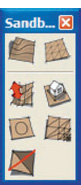
FIG 4.1 SketchUp’s Sandbox tools.
In addition to the mouse and keyboard, for all my modeling work I used 3D Connexions’ Space Explorer, a peripheral that allows me to navigate efficiently around the model. In addition to the main joystick, it has several programmable buttons to which you can assign SketchUp’s tools and commands.”
Stage 1: Gathering the Data
Objective: To bring together all the information needed for modeling
Data: Plans of the project area, photographs of the site and of the built context, surveys of the heights of the cornices of buildings surrounding the square, aerial photograph of the site
Tools: Pencil sketches, laser telemetry to measure the buildings surrounding the square, digital camera
First of all, a visit to the square and produced thorough notes of all the visible elements that needed to be modeled. Once the notes were done, the survey of cornice heights and the photographs of the square allowed the modeling of the existing elements that would be conserved throughout the project: buildings, spaces bordering on the square, street furniture or street lighting, etc.
The aerial photograph, taken from the community digital photograph survey provided by the region of Wallonia, provided additional information on the front-to-back depth of the buildings.
After this data was collected, two versions of the project plan were prepared:
• A paper version on which all the necessary levels for modeling the project were marked.
• A digital version in DWG format for import into SketchUp, which would serve as a template for modeling.
Stage 2: Preparation and Import of Plan Files
Objectives: Optimizing the files to be imported into SketchUp and adjusting the import properties
Data: Dimensioned drawing of the square
Tools: AutoCAD LT to prepare the file in DWG format
To make the template, all the existing line drawings of the square were merged into a single file. In order to cut down on the file size as much as possible before it was imported into SketchUp, all the nonmodeling elements were deleted. All the line elements were then transferred to a single layer. The file was then purged in order to delete all inessential information: empty layers, unused blocks, external references, etc.
Once the file was saved, it could be imported into SketchUp. In SketchUp’s menu bar, go to File > Import; from the drop-down menu in the resulting dialog box, choose ACAD Files (*.dwg, *.dxf), and click on the Options button. In the dialog box that appears, choose meters as the unit from the Scale drop-down menu and click on OK twice. The file is now ready to serve as a template for modeling.

FIG 4.2 Imported project template.
Stage 3: Modeling the Project
Objectives: Modeling the entire square and organizing the elements of the model
Data: Paper plan of the project with levels; color swatch chart for the materials; supplementary components for the project entourage such as vegetation, street furniture and lighting, vehicles, and pedestrians
Tools: SketchUp, plug-ins, Google 3G Warehouse online component library
To model the whole of the projected terrain, the square was divided into logical subgroups such as roadways, sidewalks, and esplanades, which were further subdivided according to different material types or sudden changes in level (curbs, terraces, etc.).
Sidewalk curbs and any other structures were modeled and combined with the previously created surface to obtain the final terrain model.
Stage 3.1: Surface Modeling
The surfaces were modeled one-by-one in the following stages:
1. Contour elevations
2. Surface modeling
3. Any necessary retouching followed by application of materials
In order to set up the contour elevations of the surface, I used Chris Fullmer’s Three Line Tools plug-in. By clicking on the Vertical Lines by Length option and then on a point in the model, one can enter the elevation height of the line directly in the VCB. Then you just need to hit Enter to set the elevation of the line. I followed the same procedure for all the points that described the boundary of the square and for all the intermediate elevation points that were necessary to model the precise contours of the square’s surface. In order to model the square’s surface, I joined all the elevation points of the perimeter using the Line tool, and then deleted the perimeter verticals.

FIG 4.3 Elevating the contours with the Three Line Tools plug-in.
As there were not enough perimeter verticals to properly describe the curve of the square’s perimeter, the following method was used: The curve shown in Figures 4.4–4.6 corresponded to three perimeter verticals, so the tops of these were joined using the Line tool. Then, by using the Line tool again, a line was traced in the X (red) axis from the lower perimeter vertical back to the middle perimeter vertical, forming a triangular surface. The same was done for the higher perimeter vertical (Fig. 4.5). This resulted in a triangulated surface that represented the fall across the two ends of the curve.
The Extrusion function of the Projections plug-in was used to extrude the curve on the DWG-derived plan so that it intersected with the newly created triangular surface (Fig. 4.6). Both the extruded curve and the triangulated surface were now selected and intersected using the Intersect Selected function (right-click on the selection and choose from the contextual menu). The extruded and triangulated surfaces were then deleted, leaving only the curve. This process was repeated for the entire perimeter of the square.

FIG 4.4 Parts of square’s outline to be modeled.

FIG 4.5 Modeling the slope of the curve.
The entire perimeter was then selected, as well as any isolated verticals. Then, from the Sandbox tools, From Contours was selected. After a short wait for the calculation, the surface was created and automatically grouped.

FIG 4.6 Intersecting the slope with the outline.
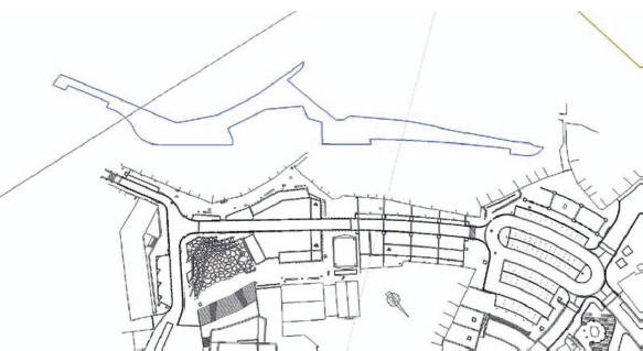
FIG 4.7 Perimeter of the surface, raised off the plan.
Tip
The Sandbox tools only work with contours: They will not work with a cloud of isolated elevation points. You can get around this limitation by using vertical lines whose ends correspond to the isolated points. The Sandbox will then take these vertical lines into account when generating the surface, but will ignore their lower extremities.

FIG 4.8 Surface generated by the Sandbox tools.
With complex surfaces, the Sandbox tool often generates faces outside the perimeter of the desired surface. To delete these faces, you can enter the surface group and, from the menu bar, choose View > Hidden Geometry. This allows you to see any hidden edges that lie outside the contour surface. You can then delete these using the Eraser tool.
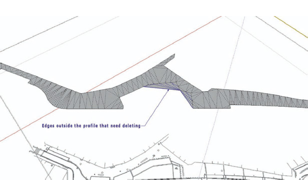
FIG 4.9 Cleaning up the faces outside the perimeter.
The surface was then assigned a color using the Paint Bucket tool. At this stage, you can Copy–Paste the surfaces just created into a second model inside the same file. This way, you can get the already created surfaces out of your way and begin drawing the next surfaces using the imported DWG file as a template. Any previously created contours can be easily reused if required. The bounding box around the model can also be used to put elements back rapidly and without error.

FIG 4.10 Surface moved to one side, given a material.
Stage 3.2: Modeling the Curbs
The curbs were modeled directly from the Sandbox surface derived in the previous stage, which represents the sidewalk. The edges of this sidewalk surface were selected and, using the Extrusion function of the Projections plug-in, the entire pavement surface was extruded in the Z axis up to the curb height (see Fig. 4.11). The Projections plug-in must be used here because SketchUp’s normal Push/Pull tool works only on planar faces.

FIG 4.11 Extrusion of the edges of the curb.
Often, this extrusion generates polygons with flipped faces – the blue back faces will point outward. For final rendering in Kerkythea, it is essential that all faces in the model have their front face showing; otherwise, Kerkythea it will not “see” the surface. The Front Face plug-in was used to flip the faces back again: By simply running the cursor over the flipped faces, they are flipped back automatically. Then you can just click on the Select tool to terminate the Front Face operation.
The Tools on Surface plug-in was then used to carry out an Offset on Surface operation for the part of the sidewalk surface that corresponds to the width of the curb. Since the offset operation is carried out all around the perimeter of the surface, the Line on Surface and Erase Contours on Surface functions of the plug-in should be used to correct any discrepancies in the offset.

FIG 4.12 Offsetting the curb.
The next stage was to create the underside of the sidewalk, corresponding to the width of the curb and the vertical extrusion corresponding to its height. These elements were selected and grouped, separating the sidewalk surfaces from those of the road.

FIG 4.13 Isolating the faces of the curb in their own group.
The same steps were taken to model stepped terraces as for the modeling of the surfaces and the curb, with the apron of each terrace being modeled like a surface and the risers between each terrace step being modeled like a curb.

FIG 4.14 The modeled terraces.
Stage 3.3: Modeling the Buildings and Other Built Elements
At the center of the model of Place Van Zeeland, three types of buildings had to be constructed that corresponded to three levels of detail, based on the size and the function of the buildings. The residential premises were modeled very quickly, since their role in the model was to show the sizes and the different sorts of openings in the façades that surround the square.
Another architect modeled the building that faces the amphitheater, imported it into SketchUp, and cleaned it up to reduce its poly count as much as possible. Materials were then applied to this model according to the color chart that was put together from on-site photographs.
The former school was modeled in more detail, since it has a very imposing presence at the southeast of the square. The same was done for the school near the covered market, reproducing the characteristic rhythm of the fenestration on the main façades.

FIG 4.15 The model of the cultural centre.

FIG 4.16 The model of the school.

FIG 4.17 The model of the former school.
The covered market, which was one of the centerpieces of the project, had been modeled in some detail since the preproject stages because of its central role in the regeneration of the square and because we wanted to put particular emphasis on its final appearance, particularly on its white-painted, tubular-steel framework (see Fig. 4.18).

FIG 4.18 The model of the covered market.
Stage 3.4: Adding the Entourage
Placing the discrete elements from the project (education, vehicles, pedestrians, and street furniture) can be fiddly and time consuming, especially if you have a lot of complex components.
Here, the positions for each type of component were marked out by using basic forms, like simple cubes. For each type of component (trees, pedestrians, etc.), a basic symbol was defined that could be placed quickly and easily into the model. This means SketchUp’s graphical display does not slow down while you are working with it.
Once all these basic placeholders are in the scene, they can all be replaced by their more complex counterparts. Simply right-click, and from the contextual menu choose Reload option. Then select the replacement component from the window that opens.
If you want to work with components, you can generally find anything that you want in Google’s 3D Warehouse. Any components that do not fit your needs exactly can always be reworked in SketchUp to suit your working methods and your graphical style.
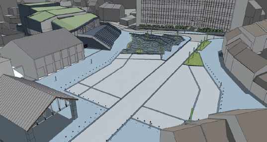
FIG 4.19 Putting in the placeholder components.
Tip
Placing components precisely on complex surfaces can prove to be difficult, mainly because of SketchUp’s inference system, which can sometimes get in the way. The Drop to Intersection Ruby plug-in makes this operation easy, allowing you to drop components placed above a surface directly onto it.
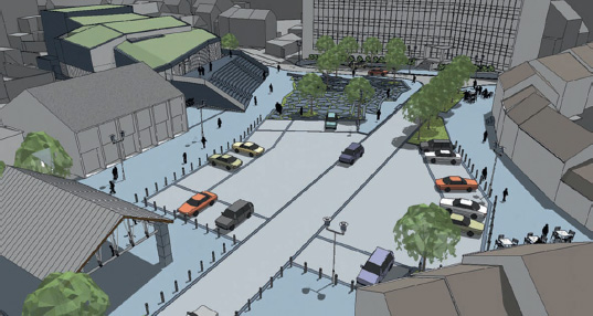
FIG 4.20 Model updated with the final, detailed components.
Stage 3.5: Assigning Model Elements to Layers
If necessary, the surfaces generated can be subdivided by projecting the outlines of drainage channels, paving borders, and other landscaping elements from the imported DWG. This can be done by using the Project function from the Sandbox tools: Select the template DWG, click on Project, and click on the surface to be subdivided. At this stage, you can explode the initial surface group and regroup according to your newly created surfaces.
Since each group is associated with a particular material, the model was organized using SketchUp’s Layer by Material option. Additionally, naming each group as you create it enables you to more easily find your way up and about within your model using the Outliner palette (from the Menu, choose Window > Outliner).
There is also a plug-in called Layer Manager that offers some additional options for the management and use of layers in SketchUp. In our practice, we increasingly use this plug-in on complex models like the Place Van Zeeland project.
Tip
The Project function from the Sandbox tools should be used only with caution: If too many elements are selected, it can cause SketchUp to crash. You should always save your model before using Project, and if the operation does not work as hoped at first, you can run it multiple times on the same surface to achieve the desired effect. If the same problems occur repeatedly, you can use the Extrude Edges function of the Projections plug-in, intersecting the extruded faces with the target surface.
Stage 4: Rendering Scenes in Kerkythea
Objectives: Preparing the scenes and the animation path for export into Kerkythea
Data: Color swatch chart based on the materials used in the project
Tools: SketchUp and Kerkythea
For the Place Van Zeeland project, a simplified color swatch chart was chosen based on a unified range of colors. The level of detail in the project did not justify the use of more realistic textures; furthermore, photorealism was never the goal of this model.
Scenes were created in SketchUp that corresponded to particular views that we wanted to render in Kerkythea. Features like the time of year, day, and shadows were then defined by clicking on the Shadow Settings icon (see Fig. 4.21). For specifying shadow settings on the Mac, from the Menu Bar choose Window > Shadows. Once all these parameters were set, the scene was added to the Scenes palette by clicking on the “+” button.
Once all the various scenes were created, the model was sent down the pipeline to Kerkythea by clicking on the Export Model to Kerkythea icon. In the dialog box that appears, click on YES to choose the options Exported Geometry and Export Lights. You should choose NO for all the other options, and then click OK. Now it is just a question of choosing an appropriate filename and clicking on the Save option. Once the export process is complete, the model can be opened directly in Kerkythea.
Rendering can now be started directly: From the Menu Bar, choose Render > Start. Parameters can also be set from the Camera and Settings window. For the Place Van Zeeland renders, the Ambient Occlusion setting was chosen, since this gives a good approximation of radiosity without the time and calculation overheads.
Kerkythea offers many more advanced photorealistic rendering possibilities, should you need them. It can also be used for the creation of walk-through animations: Kerkythea simply takes the scenes that are stored in the imported file and uses them as keyframes, “tweening” all the intermediate frames as necessary.
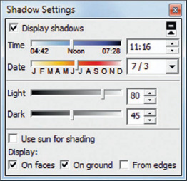
FIG 4.21 SketchUp’s shadow settings palette.

FIG 4.22 Kerkythea’s dialog box for rapid rendering setup.
In our practice, SketchUp fits perfectly into our production pipeline: First, it imports AutoCAD DWG files directly. Also, if you are a landscape architect, its tool set, enriched by the plug-ins created by and for the user community, gives you a terrain modeling tool that is almost made to measure. SketchUp is really unmatched in efficiency and in the intuitive nature of its tools. Its approach to modeling still lets you retain the feel of traditional, hand-sketched design and is extremely easy to understand.
Still, at the end of the day, SketchUp has its limitations: As models grow in complexity, they can start to slow the program down; navigation and working on the model can become difficult, even on the most high-end graphic workstations. The limitation lies in the software, and not in the hardware.
Dealing with shadows can often prove problematic. With a complex model, shadow calculations can take several seconds, which means that navigation in real time can soon become all but impossible. On top of this, there is a bug at the heart of the OpenGL rendering engine that can create artifacts whenever a component finds itself between the camera and the source of illumination. Luckily, Kerkythea is not plagued by these problems.

FIG 4.23 View of the southwest corner of the square toward the amphitheater.
Originally intended as a tool to demonstrate the preproject design to the client, over the course of the project the model proved itself to be an indispensable means of communication on numerous occasions that we had simply not foreseen, such as meetings with other residents, project planning, and phasing of works. Finally, it was instrumental in the town being awarded second prize in a competition organized by the Walloon Land Development Ministry for recognizing the best project among subsidized community projects.

FIG 4.24 View of Place Verte, with Place Van Zeeland in the background.

FIG 4.25 View of the square looking toward the former school.

FIG 4.26 Panorama of the final, constructed terraces.
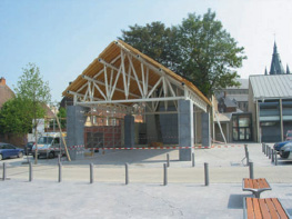
FIG 4.27 Photograph of the covered market under construction.
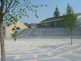
FIG 4.28 View of the cultural center seen from the terraces.
Resources
Autodesk AutoCAD LT 2007
Kerkythea Echo Render Engine 2008 (free): Available at: http://www.kerkythea.net
3D Space Explorer peripheral: http://www.3dconnexion.com/3dmouse/spaceexplorer.php
Plug-ins (All free unless otherwise stated)
These plug-ins are available on the SketchUp community forums, http://forums.sketchucation.com/ and on the CRAI-ENSAN site, http://www.crai.archi.fr/RubyLibraryDepot/Ruby/fr_RUBY_Library_Depot.html or on http://www.smustard.com
Projections version 2.0 by Didier Bur
Joint Push Pull Visual Edition by Fredo6
Tools on Surface version 1.3 by Fredo6
Three Line Tools by Chris Fullmer
Drop to Intersection by TBD
Front Face by Tomasz ($10).
Layer Manager by Didier Bur