
The line follower of GoPiGo3 is composed of six pairs of LED phototransistors. The LED emitter is the right-most part of each pair when you position the sensor in front of you to read the letters. This can be seen in the following photograph, which is a picture of the powered sensor, although you cannot yet see the LED light beams:

Why don't you see them in the picture? Because LEDs emit infrared light, which can't be detected by your eyes; however, it can be revealed by a phone camera (by default, the optics of these cameras do not include infrared filters). So, if, later on, you find that the line follower does not work properly, the first thing you must check is the hardware. To do this, simply take a photo with the camera app that ships with your smartphone.
In the following image, the sensor view has been intentionally blurred so that you can see the rays and confirm that the light beams come from the right-hand side of the LED phototransistor. The receiving part—that is, the phototransistor—is the component that detects whether there is reflected light coming from the LED emitter. The product page for this component can be viewed at https://www.dexterindustries.com/product/line-follower-sensor/:

Now, you are in a position to understand the working principles of the line-follower sensor:
- If the rays are reflected off the floor because it is white, the phototransistor receives the mirrored beam and provides this information in the data sensor stream.
- If the sensor is over a black surface, the phototransistor does not receive any reflected light and lets the robot know.
Reflection makes the sensor electronics report a signal close to 1 (white surface), while absorption provides a value close to 0 (black surface). But what if the sensor is far away from the floor or not facing it? Well, from the point of view of the sensor, absorption is equivalent to the lack of reflection. Therefore, the reported signal is close to zero. This property allows GoPiGo3 not only to follow a black path on the ground, but also to walk along edges avoiding drops that could damage the robot.
Since you have six pairs, you will have six signals, where each reports 0 or 1. These six numbers will allow us to infer how well centered the robot is over a black line. The sensor's specifications are as follows:
- I2C sensor with a Grove connector.
- Six analog sensors, each giving a value between zero and one, depending on how much light it receive from the floor, with 0 indicating black and 1 indicating white.
- The sensor can be polled up to 120 Hz.
- An easy library (https://di-sensors.readthedocs.io/en/master/api-basic.html#easylinefollower) and a driver-level library (https://di-sensors.readthedocs.io/en/master/api-advanced.html#linefollower) are available and fully documented. The easy library provides methods that do the heavy lifting for you.
The following is a bottom view of the emitter-receiver. This face is the one that has to be a few millimeters above the floor to ensure a proper reflection of the LED's emission:

The following image shows the line follower sensor mounted on the GoPiGo3 at the proper position—that is, above the floor:
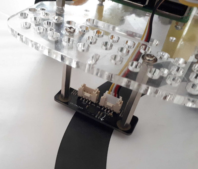
For instructions on how to assemble and calibrate the sensor, go to https://www.dexterindustries.com/GoPiGo/line-follower-v2-black-board-getting-started/. For connecting, you can use either of the two available I2C connectors on the line-follower sensor. Remember that one of them will be in use by the distance sensor.
The line follower can also be connected to one of the AD ports if you are using Raspbian For Robots (https://www.dexterindustries.com/raspberry-pi-robot-software/). It's for more advanced use, and coding for this setup is slightly different.
For the purposes of introducing robotics, we will take it easy by connecting the sensor to an I2C port and use the more friendly DexterOS (https://www.dexterindustries.com/dexteros/). In Chapter 2, Unit Testing of GoPiGo3, we will go over a specific test you can run with your robot to check that this unit works properly.