

I/O virtualization
I/O virtualization is the process of allowing a single I/O adapter to be used by many virtual machines. It is very common for network, storage, and USB.
There are basically three types of I/O virtualization, all covered in this chapter:
•Hypervisor virtualization
•Hardware virtualization
•Device assignment without virtualization (passthrough)
6.1 Types of virtualization
With hypervisor virtualization, the I/O device is virtualized by the hypervisor. In this model, the hypervisor needs to multiplex the virtual devices and control the I/O on the real devices.
6.1.1 PowerKVM supported devices
As part of I/O virtualization, IBM PowerKVM supports the following device modes:
•Storage
– virtio-scsi
– virtio
– spapr-vscsi
•Network
– virtio
– e1000 (Intel)
– RTL (Realtek)
– spapr-vlan
•Graphic models
– VGA
|
Note: The SPICE graphical model is not supported for IBM PowerKVM v2.1.
|
6.1.2 PCI I/O passthrough
I/O passthrough is not a method of I/O virtualization. It consists of giving a guest direct access to an I/O device. The adapter is assigned to a virtual machine, and the virtual machine can use this I/O exclusively.
For more information about I/O passthrough, see 6.4, “I/O passthrough” on page 98.
|
Note: On PowerKVM version 2.1 the PCI passthrough function is a technology preview.
|
6.2 Network virtualization
A virtual machine frequently needs to have network connectivity to access external servers and other virtual machines. The network is an important area in virtualization. Currently, there are different ways to allow a virtual machine to access the external network, and those methods are explained breifly in this chapter.
A network card be assigned directly to the VM using the I/O passthrough method.
These are the current network virtualization methods that are available:
•User mode networking
•NAT networking
•Bridged networking
•PCI passthrough
•Open vSwitch
See 3.3, “Network” on page 52 for how to create NAT and bridged networks by using Kimchi.
6.2.1 User mode networking
In this scenario, the traffic is sent through QEMU by using a user space socket that drives the packet to the whole network. This mode also uses the concept of network address translation (NAT) to translate packets from one VM to the external network. The big advantage of user mode networking is that the users on the system do not need to have privileged permissions to enable networking on the guest.
|
Note: In the QEMU emulator, user mode networking is called SLIRP:
|
Considerations
The main consideration of this scenario is that the virtual machine is not visible from the external network. For example, the virtual machine will be able to access the Internet, but it will not be able to host an external accessible web server.
There are also two other considerations:
•There is significant overhead during the packet translation, which makes the performance very poor.
•Internet Control Message Protocol (ICMP) does not work with the user mode networking approach.
6.2.2 Network address translation networking
Network address translation (NAT) networking uses a range of IPv4 private addresses in the guests and translates those addresses to a host address when routing to the external network. Guests that are using the same NAT network can communicate directly, as if they were on the same Ethernet broadcast domain.
6.2.3 Bridged networking
This is the approach that gives better performance than user mode, mainly because the guest network interface is exposed to the external network. Consequently, it can be accessed externally as with a non-virtualized system, as shown in Figure 6-1 on page 94.
A network bridge is an interface that connects other network segments that are described by IEEE 802.1D standard.
A bridge is capable of passing Layer 2 packets using the attached network interfaces. Because the packet forwarding works on Layer 2, any Layer 3 protocol works transparently.
The main limitation of bridged networking is that most wireless adapters do not accept it.

Figure 6-1 Bridge architecture
To manage the bridge architecture on the host, use the brcrtl command. For example, to create a bridge network interface, execute the following command:
# brctl addbr <example_bridge_device>
6.2.4 Open vSwitch
Open vSwitch is an open source, multilayer distributed virtual switch. It supports standard management protocols and interfaces, such as NetFlow, sFlow, SPAN, LACP, and 802.1ag. The key advantage of it that Open vSwitch can be distributed across many physical machines. By providing APIs for automation, Open vSwitch becomes an almost perfect solution for OpenStack deployments.
If you already created a bridge with linux-bridge-tools, you can’t reuse that bridge. The bridge must be re-created by using ovs tools.
It is required to have Open vSwitch service up and running before plugging virtual machines into the Open vSwitch network. See “Configuring network from CLI” for information about the initial configuration.
See the documentation on the Open vSwitch website for more information:
6.3 Storage pools
A storage pool is a pool of disks that are in the hypervisor and can be assigned to virtual machines. Different storage pools can be created and backed up by different technologies:
•File system directory
•Physical disk device
•Preformatted block device
•iSCSI target
•Logical Volume Manager (LVM) volume group
•Multipath devices
•Network exported directory
•SCSI host adapter
6.3.1 Storage volume
A storage volume is a storage device that is usually assigned to a guest as a virtual disk. The virtual machine sees the device as a physical disk. The physical location of this block depends on the storage pool configuration.
Storage pools can be logically divided in two categories. Block device and file-backed pools.
6.3.2 Block device pools
Block device pools are pools such as the following kinds that reside on block devices:
•Logical volume pool
A virtual machine volume created on top of an LVM pool is an LVM logical volume.
•iSCSI volume pool
A volume in an iSCSI pool is a LUN presented by the iSCSI target, as shown in Figure 6-3 on page 96.
•SCSI volume pool
A volume in a Fibre Channel (FC) pool is a LUN that is mapped to specific scsi_host adapter, as shown in Figure 6-5 on page 97.
•Disk volume pool
A volume in such a pool is a partition on the physical disk.
|
Note: You can’t create new volumes on iSCSI and SCSI through a libvirt API. Volumes must be created manually on a target, instead.
|
6.3.3 File-backed pools
File-backed pools are file systems mounted to PowerKVM host. There are two types: File system pools and network file system pools.
File system pool
A volume in a file system storage pool is an image file that is stored in specified format, as shown in Figure 6-2 on page 96.
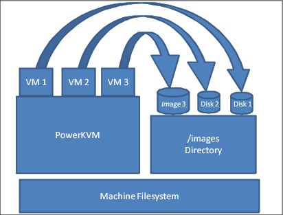
Figure 6-2 File-backed pool
The file system can be backed by iSCSI, as shown in Figure 6-3.

Figure 6-3 iSCSI-backed storage pool
Network file system pool
This is nearly the same as a file system pool, but it is hosted on a remote file system (NFS), as shown in Figure 6-4 on page 97.

Figure 6-4 NFS backed Storage Device
Either file system type can be on iSCS or Fibre Channel, as shown in Figure 6-5.

Figure 6-5 Fibre Channel-backed storage device
6.4 I/O passthrough
I/O passthrough is a method to give to the virtual machines the I/O adapters that are plugged into the host machine. There are three types:
•SCSI passthrough
•USB passthrough
•PCI passthrough
6.4.1 SCSI passthrough
By default, QEMU is between the virtual machine and the physical block device. It provides a general SCSI device to a virtual machine. If you want to connect a passthrough SCSI device directly to a VM, set device='lun' as Example 6-1 shows.
Example 6-1 LUN passthrough
<disk type='block' device='lun'>
<driver name='qemu' type='raw'/>
<source dev='/dev/sdn'/>
<target dev='sda' bus='scsi'/>
<address type='drive' controller='0' bus='0' target='3' unit='0'/>
</disk>
6.4.2 USB passthrough
It is also possible to pass through a USB host device to a virtual machine that is running under PowerKVM. First, determine the vendor and ID values of the device by using the lsusb command. The output is shown in Example 6-2.
Example 6-2 lsusb command output
[root@powerkvm ~]# lsusb
Bus 001 Device 003: ID 058f:6387 Alcor Micro Corp. Flash Drive
Bus 001 Device 001: ID 1d6b:0002 Linux Foundation 2.0 root hub
Bus 002 Device 001: ID 1d6b:0001 Linux Foundation 1.1 root hub
Bus 003 Device 001: ID 1d6b:0001 Linux Foundation 1.1 root hub
|
Note: There are limitations, though:
•Only USB 2.0 and USB 3.0 devices work for USB passthrough.
•The device must not be used by the host system at the same time that the virtual machine is using it. To prevent that, kernel modules must be unloaded with the rmmod command.
•If the device is a flash drive, the only requirement is to not have it mounted by host.
|
You must prepare an XML file with a device description. There are two options available:
|
Tips: We’ve discovered during testing that vendor, product definition works only with a cold plug (the virtual machine is in shut-off state). The bus, device combination works quite well for a hot plug.
|
Example 6-3 USB XML description example based on vendor, product (IDs) pair
<hostdev type='usb'>
<source>
<vendor id='0x058f'/>
<product id='0x6387'>
</source>
</hostdev>
Example 6-4 USB XML description example based on bus, device pair
<hostdev type='usb'>
<source>
<address bus='1' device='3'/>
</source>
</hostdev>
Example 6-5 shows how to check what it is currently connected to the virtual machine.
Example 6-5 lsusb command output from a virtual machine
sles11vm01:~ # lsusb
Bus 001 Device 001: ID 1d6b:0001 Linux Foundation 1.1 root hub
When you are ready to add the device, you can plug it in by using the virsh attach-device command, as shown in Example 6-6.
Example 6-6 Attach the device to a VM
# virsh attach-device sles11vm01 usb-bus.xml
Device attached successfully
# virsh console sles11vm01
Connected to domain sles11vm01
Escape character is ^]
# lsusb
Bus 001 Device 001: ID 1d6b:0001 Linux Foundation 1.1 root hub
Bus 001 Device 003: ID 058f:6387 Alcor Micro Corp. Transcend JetFlash Flash Drive
|
Note: To make live change persistent, use the --persistent option.
|
To detach a USB device, use the virsh detach-device command, as shown in Example 6-7.
Example 6-7 Detaching a USB device from a guest
# virsh detach-device sles11vm01 usb-bus.xml
Device detached successfully
# virsh console sles11vm01
Connected to domain sles11vm01
Escape character is ^]
# lsusb
Bus 001 Device 001: ID 1d6b:0001 Linux Foundation 1.1 root hub
sles11vm01:~ #
6.4.3 PCI passthrough to a virtual machine
To pass through a specific adapter to a virtual machine, the adapter first needs to be described in an XML-formatted file. You can use either lspci (see Example 6-8) or virsh nodedev-list | grep pci (see Example 6-9 on page 101) to find the device address of a card that you want to pass through.
Example 6-8 lspci command output
# lspci
0000:00:00.0 PCI bridge: IBM Device 03b9 (rev 10)
0000:01:00.0 PCI bridge: PLX Technology, Inc. PEX 8624 24-lane, 6-Port PCI Express Gen 2 (5.0 GT/s) Switch [ExpressLane] (rev bb)
0000:02:04.0 PCI bridge: PLX Technology, Inc. PEX 8624 24-lane, 6-Port PCI Express Gen 2 (5.0 GT/s) Switch [ExpressLane] (rev bb)
0000:02:05.0 PCI bridge: PLX Technology, Inc. PEX 8624 24-lane, 6-Port PCI Express Gen 2 (5.0 GT/s) Switch [ExpressLane] (rev bb)
0000:02:06.0 PCI bridge: PLX Technology, Inc. PEX 8624 24-lane, 6-Port PCI Express Gen 2 (5.0 GT/s) Switch [ExpressLane] (rev bb)
0000:02:08.0 PCI bridge: PLX Technology, Inc. PEX 8624 24-lane, 6-Port PCI Express Gen 2 (5.0 GT/s) Switch [ExpressLane] (rev bb)
0000:02:09.0 PCI bridge: PLX Technology, Inc. PEX 8624 24-lane, 6-Port PCI Express Gen 2 (5.0 GT/s) Switch [ExpressLane] (rev bb)
0000:40:00.0 RAID bus controller: IBM Obsidian-E PCI-E SCSI controller (rev 01)
0000:60:00.0 RAID bus controller: IBM Obsidian-E PCI-E SCSI controller (rev 01)
0000:80:00.0 PCI bridge: PLX Technology, Inc. PEX8112 x1 Lane PCI Express-to-PCI Bridge (rev aa)
0000:90:01.0 USB controller: NEC Corporation OHCI USB Controller (rev 43)
0000:90:01.1 USB controller: NEC Corporation OHCI USB Controller (rev 43)
0000:90:01.2 USB controller: NEC Corporation uPD72010x USB 2.0 Controller (rev 04)
0000:a0:00.0 Ethernet controller: Broadcom Corporation NetXtreme BCM5719 Gigabit Ethernet PCIe (rev 01)
0000:a0:00.1 Ethernet controller: Broadcom Corporation NetXtreme BCM5719 Gigabit Ethernet PCIe (rev 01)
0000:a0:00.2 Ethernet controller: Broadcom Corporation NetXtreme BCM5719 Gigabit Ethernet PCIe (rev 01)
0000:a0:00.3 Ethernet controller: Broadcom Corporation NetXtreme BCM5719 Gigabit Ethernet PCIe (rev 01)
0001:00:00.0 PCI bridge: IBM Device 03b9 (rev 10)
0001:01:00.0 Ethernet controller: Mellanox Technologies MT26448 [ConnectX EN 10GigE, PCIe 2.0 5GT/s] (rev b0)
0002:00:00.0 PCI bridge: IBM Device 03b9 (rev 10)
0002:01:00.0 RAID bus controller: IBM Obsidian-E PCI-E SCSI controller (rev 01)
0003:00:00.0 PCI bridge: IBM Device 03b9 (rev 10)
0003:01:00.0 RAID bus controller: IBM Obsidian-E PCI-E SCSI controller (rev 01)
0004:00:00.0 PCI bridge: IBM Device 03b9 (rev 10)
0004:01:00.0 RAID bus controller: IBM Obsidian-E PCI-E SCSI controller (rev 01)
0005:00:00.0 PCI bridge: IBM Device 03b9 (rev 10)
0005:01:00.0 RAID bus controller: IBM Obsidian-E PCI-E SCSI controller (rev 01)
Example 6-9 virsh nodedev-list command output
# virsh nodedev-list | grep pci
pci_0000_00_00_0
pci_0000_01_00_0
pci_0000_02_04_0
pci_0000_02_05_0
pci_0000_02_06_0
The next example shows passing through a Mellanox adapter. As you can see in Example 4-22, the device has a 0001:01:00.0 PCI address, and virsh represents it as pci_0001_01_00_0. To make sure that you’ve found the correct match, using virsh nodedev-dumpxml pci_0001_01_00_0 will provide more information about the device, as shown in Example 6-10.
Example 6-10 virsh nodedev-dumpxml command output
# virsh nodedev-dumpxml pci_0001_01_00_0
<device>
<name>pci_0001_01_00_0</name>
<path>/sys/devices/pci0001:00/0001:00:00.0/0001:01:00.0</path>
<parent>pci_0001_00_00_0</parent>
<driver>
<name>mlx4_core</name>
</driver>
<capability type='pci'>
<domain>1</domain>
<bus>1</bus>
<slot>0</slot>
<function>0</function>
<product id='0x6750'>MT26448 [ConnectX EN 10GigE, PCIe 2.0 5GT/s]</product>
<vendor id='0x15b3'>Mellanox Technologies</vendor>
<iommuGroup number='4'>
<address domain='0x0001' bus='0x01' slot='0x00' function='0x0'/>
</iommuGroup>
</capability>
</device>
Next, the PCI adapter needs to be detached from a host system. You can use the virsh nodedev-detach command to do that (see Example 6-11).
Example 6-11 virsh nodedev-detach command
# virsh nodedev-detach pci_0001_01_00_0
Device pci_0001_01_00_0 detached
After the PCI adapter is detached from the system, the adapter needs to be described in a virtual machine configuration. To put the adapter description in the <devices> section, edit the virtual machine configuration by using the virsh edit command (see Example 6-12). Then, save the file, and the machine is ready to be started.
Example 6-12 PCI adapter description
# virsh edit sles11vm01
<hostdev mode='subsystem' type='pci' managed="yes">
<source>
<address domain='0x0001' bus='0x01' slot='0x00' function='0x00'/>
</source>
<driver name=’vfio’/>
</hostdev>
|
Note: The status of the managed mode can be either “yes” or “no:”
•yes: libvirt will unbind the device from the existing driver, reset the device, and bind it to pci-stub
•no: You must take care about those aspects manually
|
Now, you’re ready to start the guest with the assigned adapter. In Example 6-13, you can see that the virtual machine detects the card correctly. Example 6-14 shows that additional Ethernet interfaces are available.
Example 6-13 lspci command output within the VM
sles11vm01:~ # lspci
0000:00:01.0 Ethernet controller: Red Hat, Inc Virtio network device
0000:00:02.0 USB controller: Apple Inc. KeyLargo/Intrepid USB
0001:00:00.0 Ethernet controller: Mellanox Technologies MT26448 [ConnectX EN 10GigE, PCIe 2.0 5GT/s] (rev b0)
Example 6-14 List of available interfaces
# ip a s
1: lo: <LOOPBACK,UP,LOWER_UP> mtu 16436 qdisc noqueue state UNKNOWN
link/loopback 00:00:00:00:00:00 brd 00:00:00:00:00:00
inet 127.0.0.1/8 brd 127.255.255.255 scope host lo
inet 127.0.0.2/8 brd 127.255.255.255 scope host secondary lo
inet6 ::1/128 scope host
valid_lft forever preferred_lft forever
2: eth0: <BROADCAST,MULTICAST,UP,LOWER_UP> mtu 1500 qdisc pfifo_fast state UP qlen 1000
link/ether 52:54:00:de:18:a2 brd ff:ff:ff:ff:ff:ff
inet 192.168.122.213/24 brd 192.168.122.255 scope global eth0
inet6 fe80::5054:ff:fede:18a2/64 scope link
valid_lft forever preferred_lft forever
3: eth1: <BROADCAST,MULTICAST> mtu 1500 qdisc noop state DOWN qlen 1000
link/ether 00:02:c9:2b:98:00 brd ff:ff:ff:ff:ff:ff
4: eth2: <BROADCAST,MULTICAST> mtu 1500 qdisc noop state DOWN qlen 1000
link/ether 00:02:c9:2b:98:01 brd ff:ff:ff:ff:ff:ff
6.4.4 I/O limits
It is possible to override certain properties of the block device, such as disk geometry or logical and physical block sizes. Those tunables might be especially useful during development and testing of software on a PowerKVM virtual machine. Example 6-15 shows examples of how to use <blockio>, <geometry>, and <target> within the <disk> element.
Example 6-15 Change disk properties
<disk type='block' device='disk'>
<driver name='qemu' type='raw'/>
<source dev='/dev/sdn'/>
<target dev='sda' bus='scsi'/>
<geometry culs='16383' heads='16' secs='63' trans='lba'/>
<blockio logical_block_size='512' physical_block_size='4096'>
</disk>
It is also possible to limit I/O throughput of a device with the <iotune> subelement of a <disk> element. These are the options:
total_bytes_sec Total throughput limit in bytes per second
|
Note: total_bytes_sec conflicts with read_bytes_sec and write_bytes_sec.
|
read_bytes_sec Read throughput in bytes per second
write_bytes_sec Write throughput in bytes per second
total_iops_sec Total I/O operations per second
|
Note: total_iops_sec conflicts with read_iops_sec and write_iops_sec.
|
read_iops_sec Read I/O operations per second
write_iops_sec Write I/O operations per second
Example 6-16 shows the complete <disk> element of a virtual machine.
Example 6-16 iotune example of a disk element
<disk type='file' device='disk'>
<driver name='qemu' type='qcow2' cache='none'/>
<source file='/var/lib/libvirt/images/sles11vm04.qcow2'/>
<target dev='sda' bus='scsi'/>
<address type='drive' controller='0' bus='0' target='0' unit='0'/>
<iotune>
<total_bytes_sec>10000000</total_bytes_sec>
<read_iops_sec>400000</read_iops_sec>
<write_iops_sec>100000</write_iops_sec>
</iotune>
</disk>
6.5 Hot plug
You can use a hot plug to add or remove devices on the system while it is online, without rebooting the system. This section covers SCSI disk hot plugs to the guest that is running under PowerKVM.
|
Note: The PowerKVM 2.1 release does not support PCI, CPU, or memory hot plugs for the guests. Those capabilities are likely to be added in future releases.
|
To add a disk to the guest online, use the virsh attach-disk command, as shown in Example 6-17.
Example 6-17 vSCSI disk hot plug
# virsh attach-disk sles11vm04 --source /var/lib/libvirt/images/sles11vm04_1.qcow2 --target sdf
Disk attached successfully
The disk hot plug works in the same way. A new LUN will be attached to existing SCSI bus of a guest. If the guest has multiple SCSI adapters defined, libvirt picks the first one. If you want to use a specific one, use the --address argument.
After the disk is hot plugged to the guest, rescane the SCSI bus within the guest.
|
Note: You can use the rescan-scsi-bus.sh script from the sg3-utils package to rescan.
|
Example 6-18 shows the details of the process.
Example 6-18 vSCSI hot plug attachment to the guest
on the guest:
sles11vm04:~ # lsscsi
[0:0:0:0] disk QEMU QEMU HARDDISK 1.6. /dev/sda
[0:0:0:1] cd/dvd QEMU QEMU CD-ROM 1.6. /dev/sr0
on the host:
[root@powerkvm ~]# virsh vol-create-as default hotplug.qcow2 --format qcow2 20G --allocation 1G
Vol hotplug.qcow2 created
[root@powerkvm ~]# virsh attach-disk sles11vm04 --source /var/lib/libvirt/images/hotplug.qcow2 --target sdc --persistent
Disk attached successfully
on the guest:
sles11vm04:~ # rescan-scsi-bus.sh
/usr/bin/rescan-scsi-bus.sh: line 647: [: 1.11: integer expression expected
Host adapter 0 (ibmvscsi) found.
Scanning SCSI subsystem for new devices
Scanning host 0 for SCSI target IDs 0 1 2 3 4 5 6 7, all LUNs
Scanning for device 0 0 0 0 ...
OLD: Host: scsi0 Channel: 00 Id: 00 Lun: 00
Vendor: QEMU Model: QEMU HARDDISK Rev: 1.6.
Type: Direct-Access ANSI SCSI revision: 05
Scanning for device 0 0 0 1 ...
OLD: Host: scsi0 Channel: 00 Id: 00 Lun: 01
Vendor: QEMU Model: QEMU CD-ROM Rev: 1.6.
Type: CD-ROM ANSI SCSI revision: 05
Scanning for device 0 0 0 2 ...
NEW: Host: scsi0 Channel: 00 Id: 00 Lun: 02
Vendor: QEMU Model: QEMU HARDDISK Rev: 1.6.
Type: Direct-Access ANSI SCSI revision: 05
1 new or changed device(s) found.
0 device(s) removed.
sles11vm04:~ # lsscsi
[0:0:0:0] disk QEMU QEMU HARDDISK 1.6. /dev/sda
[0:0:0:1] cd/dvd QEMU QEMU CD-ROM 1.6. /dev/sr0
[0:0:0:2] disk QEMU QEMU HARDDISK 1.6. /dev/sdb
|
Notes:
--target SDC doesn’t reflect the device name shown in the guest. Instead, it shows the name used by QEMU to identify the device. Also, based on the device name, the bus is automatically determined. Examples: sdX for vSCSI and vdX for Virtio devices, where X is a, b, c, and so on.
spapr-vscsi has a limit of 7 devices being attached to the same bus.
|
To remove a disk from the system, use the virsh detach-disk command, as shown in Example 6-19.
Example 6-19 Detach a disk from the guest
On the host:
[root@powerkvm ~]# virsh detach-disk sles11vm04 sdc
Disk detached successfully
On the guest:
sles11vm04:~ # rescan-scsi-bus.sh -r
/usr/bin/rescan-scsi-bus.sh: line 647: [: 1.11: integer expression expected
Host adapter 0 (ibmvscsi) found.
Syncing file systems
Scanning SCSI subsystem for new devices and remove devices that have disappeared
Scanning host 0 for SCSI target IDs 0 1 2 3 4 5 6 7, all LUNs
Scanning for device 0 0 0 0 ...
OLD: Host: scsi0 Channel: 00 Id: 00 Lun: 00
Vendor: QEMU Model: QEMU HARDDISK Rev: 1.6.
Type: Direct-Access ANSI SCSI revision: 05
Scanning for device 0 0 0 1 ...
OLD: Host: scsi0 Channel: 00 Id: 00 Lun: 01
Vendor: QEMU Model: QEMU CD-ROM Rev: 1.6.
Type: CD-ROM ANSI SCSI revision: 05
sg2 changed: LU not available (PQual 3)
REM: Host: scsi0 Channel: 00 Id: 00 Lun: 02
DEL: Vendor: QEMU Model: QEMU HARDDISK Rev: 1.6.
Type: Direct-Access ANSI SCSI revision: 05
0 new or changed device(s) found.
1 device(s) removed.
sles11vm04:~ # lsscsi
[0:0:0:0] disk QEMU QEMU HARDDISK 1.6. /dev/sda
[0:0:0:1] cd/dvd QEMU QEMU CD-ROM 1.6. /dev/sr0
|
Note: To find the target name of a device to detach, first find the LUN number of the device (0:0:0:2 in this example). That is the third (starting from zero) letter from the alphabet. Therefore, in this example, that is c, so that is the SDC target to detach.
|
6.5.1 Adding a new vSCSI adapter
To add more than seven devices to a vSCSI bus, a new adapter needs to be created. To do so, a guest needs to be modified with the virsh attach-device command, as shown in Example 6-20.
Example 6-20 Additional adapter definition
# cat scsi.xml
<controller type='scsi' index='2'>
<address type='spapr-vio' reg='0x4000'/>
</controller>
# virsh attach-device sles11vm04 scsi.xml --config
Device attached successfully
|
Note: --config instructs libvrit to add an adapter definition, which will be available after the next boot.
|
..................Content has been hidden....................
You can't read the all page of ebook, please click here login for view all page.