In the previous chapters we covered basic modeling techniques to construct a simple building. We skipped over many additional features so that you can get a handle on essential workflows, the user interface, and making modifications to the model. In this chapter we'll cover more advanced features that are available any time you're modeling in Revit. As you'll see, with a little refinement and creativity, you can make almost anything using standard creation tools. Topics we'll cover include:
Walls: advanced modeling features
Curtain walls: advanced design techniques
Roofs and floors: advanced shape editing
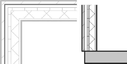
With Revit, walls are made from layers of materials that represent the construction materials used to build real walls. These layers can be assigned functions, allowing them to join and react to other similar layers in the model when walls, floors, and roofs meet. The wall core is one of these special layers, and understanding it will help you when you're designing your walls.
Revit has a unique ability to identify a wall core that is much more than a layer of material. The core influences the behavior of the wall and how the wall interacts with other elements in the model. Every wall type in Revit has a core material with a boundary on either side of it. These core boundaries can be dimensioned and snapped to. When other host elements (walls, floors, ceilings, roofs) are drawn, you can use wall-core boundaries to maintain critical relationships. For example, a floor sketch can be constrained to the structural stud layer of walls by using the wall-core boundary to create the sketch. If walls change size or are swapped, the floor sketch maintains its relationship to the core boundary and will adjust automatically.
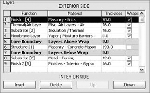
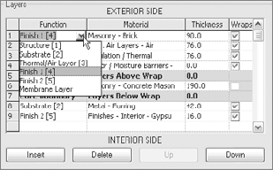
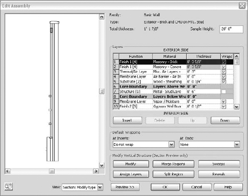
To access and edit wall-core boundaries and material layers, select a wall, select Element Properties and in the Instance Properties dialog box, click Edit Type to open Type Properties, and then click the Structure parameter. This will open a new Edit Assembly dialog box. Here you can define materials, move layers in and out of the core boundary, and assign functions to each layer (see Figure 6.1).
To get a feel for how core layers are used in relation to a floor, start a new Revit session and follow these steps:
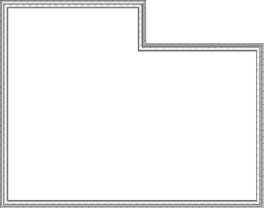
Open a new project, and draw a simple floor plan using the Wall tool. Select a multilayered wall type in order to understand the value of the exercise — the Brick on CMU wall type works well. Draw some walls in the shape shown in Figure 6.2.
Use the View Control bar to switch to fine or medium level of detail so you can see all wall layers. (In coarse views, wall layers are never displayed.)
On the Build panel of the Home tab, select the Floor tool, keep the default selected Pick Walls tool in the Draw panel, and in the Options bar (Figure 6.3) check the Extend into Wall (To core) option.
Position your mouse over an edge of the wall (do not click the mouse yet), press Tab to highlight all the walls, and then click to select. Zoom in. A sketch line indicating the shape of the floor will be created. This sketch line indicates the position of the floor relative to the wall — it's drawn at the exterior edge of the wall core. Make sure you've selected all walls as a reference to create the floor, and click Finish Sketch.
From the View tab, select the Section tool, create a section through the wall, and open the section view. Again, make sure your view is set to medium or fine level of detail. You'll see the edge of the floor and how it aligns with the wall construction (Figure 6.4).
Go back to the floor plan, and select all elements in the view. Click the Filter button on the Multi-Select tab, and uncheck all but the Floor category. Click OK. To edit the floor sketch, select the Edit Sketch tool from the Edit panel of the Modify tab. Revit returns you to Sketch mode.
Tab-select the floor lines to pick all lines in the sketch. In the Options bar, set an offset of 6″ (150 mm).
Finish the sketch by clicking the Finish Floor button in the Create Floor Boundary tab.
Switch back to the section view (Figure 6.5). The floor now extends 6″ (150 mm) beyond the edge of the core.
You can continue by changing the wall type to another type and see that the floor always maintains its position relative to the core of the new wall. If you change your design and move your walls to make the floor plan bigger or smaller, the floor will always adjust with the change.

As mentioned in Chapter 4, "Modeling Basics," the wall-layer priority determines the interaction and cleanup of joins between walls of different types. There are six functions (levels of priority of wall layers), with Structure having the highest priority (as shown in Figure 6.6).
When you create a new wall type and begin adding material layers to the wall, you need to assign a material, thickness, and priority to the layers. When you're assigning a priority, think about the function of the layer in the wall — is it finish? Substrate? Structure? This decision will help clean up your walls down the road.
If you encounter situations where the automated wall cleanup doesn't correspond to your expectations, Revit will let you cycle through a range of possible layer configurations using the Wall Joins tool, located in the Edit Geometry panel of the Modify tab.

The Wall Joins tool lets you edit wall-join configurations. The default wall join is set to butt join. Activate the Wall Joins tool, and place your mouse over a wall join. (This can be a corner where two walls meet.) The Options bar shows some alternative configuration options: Miter and Square. A miter join is shown in Figure 6.7.

Disallow Join is another tool designed to provide more flexibility in wall-join behavior. If you select a partition wall that cleans up with your exterior wall but that isn't the desired behavior for that partition wall, you can right-click the blue control dot at the end of the wall and select Disallow Join from the context menu. Doing so breaks the autojoin cleanup. Figure 6.8 shows the walls intersecting in a Disallow Join condition. Note that once a join has been disallowed, a re-allow join icon will appear when the wall that is disjoined is selected. Clicking this icon will rejoin the two walls. Note that the controls are available at wall ends (T-join of walls) and mid-end joins (vertical lines in elevation profile in the middle of the wall or in wall opening); and they only appear when a single wall is selected.
Walls in a building, especially exterior walls, are often composed of different wall types that vertically stack on top of one another over the height of the façade. At the very least, most walls sit on top of a foundation wall. To guarantee that in case the foundation wall changes position, the walls above it also move, you can create a special wall type in Revit: Stacked Wall. (See Figure 6.11 later in this section for the final look of a stacked wall.) All individual walls stacked on top of each other in a stacked wall will behave as one entity.
Stacked walls allow you to create a single wall entity composed of vertically stacked different wall types. The wall types that make up the stacked wall need to be existing types already available in the project. Note that stacked walls may only be composed of basic walls — single or multilayered — but not of curtain walls or other stacked walls.
To understand how stacked walls work and how to modify one, follow these steps:
Open a new session of Revit, and make sure three levels are defined (if you don't have three levels defined, go to an elevation view, add a third level, and then go back to your Level 1 floor plan view).
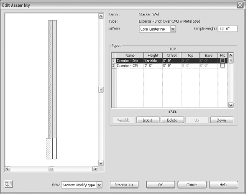
Select the Wall tool, and then click on the Change Element type: this opens the Type Selector list. Select the Stacked Wall: Exterior – Brick Over CMU with Metal Stud (located at the bottom of the list). Click the Element Properties button to open the Instance Properties dialog box, then click the Edit Type button to open the Type Properties dialog box, and then duplicate the wall type to create a new stacked wall (Figure 6.9).
Edit the Structure parameter, and click the Preview button to see the wall in section (Figure 6.10). When you're editing the stacked wall type, you'll notice that the dialog box is slightly different than when you're working with a basic wall. Rather than editing individual wall layers, this dialog box allows you to stack predefined wall types on top of each other.
Click the Insert button to add a new wall. A new row appears in the list and allows you to select a new wall. Select the Generic wall type from the Name list, and set the Height value; you also may need to define an Offset value to make the three walls flush with the interior face. With a new row selected, click the Variable button. This will allow the wall to vary in height to adjust with levels.
Go back to your plan view and draw the new wall, making sure that you set its top constraint to Level 3. In 3D, the wall should look similar to Figure 6.11.
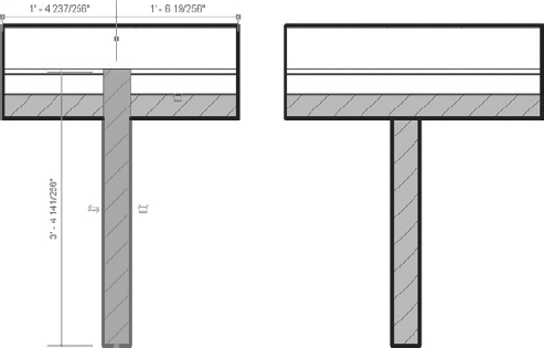
Cut a section through the model and change the heights of Level 1 and Level 3 to see the effect this has on the wall. (Make sure the level of detail is set to medium/fine to see the wall layers.) You'll see that changing Level 2 does not change the bottom walls, as they are fixed in height. However, changing the height of Level 3 will change the height of the variable wall (see Figure 6.12).


Note
In Revit it is never too late to add or change something. There is no need to rearrange things to accommodate late changes to the project, because that is exactly where Revit excels — it revises instantly when you apply a change to one place.
Walls are often complex, highly articulated compositions. Cornices, reveals, corrugated metal finish, and other projections are used all the time to give texture and delineate space. Revit can accommodate any of these types of design elements. Four examples of so-called compound walls are shown in Figure 6.13.
Note
Use these walls sparingly if you have really large projects or underpowered hardware. Model patterns are computationally much lighter than geometry.

In the Edit Assembly dialog box of any basic wall, you can enable a preview of the wall. This preview allows you to view the wall in either plan or section. When the section preview is active, additional tools also become active and allow you to place geometric sweep and reveal components on the wall (see Figure 6.14).
Clicking the Sweeps or Reveals button in the Edit Assembly dialog box opens a new dialog box where you can define profile families to use as sweeps or reveals. These profiles, which are no more than 2D shapes made out of simple lines, are then swept along the length of the wall at a specified height. Many profiles representing cornices, skirting, and chair rails are included as part of the Revit installation; but if you need to create a custom profile of your choice, you can create one using the Family Editor and the Profile Family template. To do that, open the Application Menu and choose New → Family, and then choose the profile template (Profile.rft or Metric Profile.rft). The Revit Family Editor opens with the correct template for creating your own profile; you draw one closed loop of lines at the desired real-world scale, save the family, and then load the profile back into your project. (Note that you cannot have more than one closed loop of lines when creating profiles in the Family Editor.)
Revit offers two different techniques of creating wall sweeps and reveals. In the following example, we will cover the first one, called integrated wall sweeps and reveals. Later in this chapter we will discuss the host sweeps and reveals.
To place an integrated wall sweep onto a wall type, follow these steps:
From the Home tab, click the Wall tool and select a Generic wall from the type selector.
Select Element Properties to open the Instance Properties dialog box, click Edit Type, and click Duplicate. Give the wall a new name.
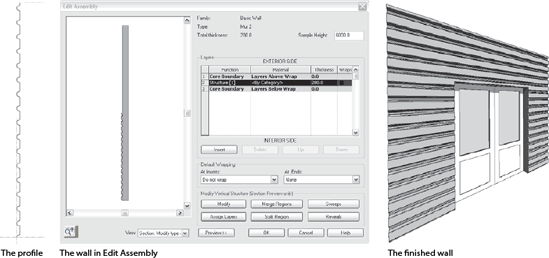
Using the Insert button, add new layers as shown in Figure 6.15. Use the Up and Down buttons to move layers in the assembly.
If not already in section view, switch the wall preview using the View drop-down menu in this dialog box. The six Modify Vertical Structure options become active at the bottom of the dialog box, as shown in Figure 6.16.
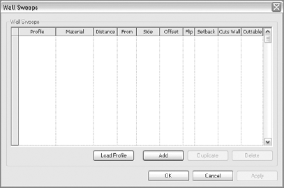
Click the Sweeps tool to open the dialog box shown in Figure 6.17. At present, no sweeps are defined in your wall, so let's add some.
Click the Load Profile button, browse to the Profiles folder, and load these two profiles, as shown in Figure 6.18:
Cornice : Metal Panel.rfaBase 2.rfa
Note that selecting those two profiles loaded them in your project, but you still have to add them to the wall sweep in order to actually use them.
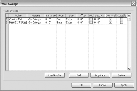
Click the Add button. This adds a row in the dialog box in which the current profile is a Default profile. Click in the first row on the Default profile. When a little arrow appears, click the arrow, and from the list of available loaded profiles, select the Cornice profile. Repeat the same in the second row and select the Base profile.
Set the Cornice profile's From value to Top and the Base profile's From value to Base. Doing so attaches the profiles to the top and bottom of your wall. Figure 6.19 shows the profiles loaded in the wall.
Click OK. Figure 6.20 shows the profiles attached to the top and bottom of the wall.
Back in the main window (the drawing area), draw a segment of this wall. Make a section through the wall and check out the wall in section and 3D views to see the resulting wall. Figure 6.21 shows the final result of the wall.


In real practice, not all layers in a single wall extend all the way from the bottom to the top of the wall: in a bathroom the tiles sometimes only go up to 5′-0″ (1.50 m) and a façade finish material may start at 20″ / 50 cm off the ground. To make it possible to have wall components finish earlier or start later within the height of the wall, there is another useful feature that enables you to unlock wall layers and manipulate their heights. Here's how to do this:
Switch to the section preview in the Edit Assembly dialog box, click Modify, and using the SteeringWheels icon, zoom in to the bottom of the wall. Hover the mouse over the bottom edges of the layers in the preview, and they will highlight.
With the help of the Tab key, select one of the bottom edges of one of the wall layers and a lock icon will appear. By default, all top and bottom edges of layers are locked into place; however, if you unlock this edge it becomes free to move up and down.
Note
Note that once you have unlocked a wall layer, you can do the actual changing of its height only in the project environment once you place a wall. This editing can't be done in the Assembly dialog box. This is why the unlocked component may not move up or down as expected.
Once the wall is placed in a project, you can manipulate individual layers dynamically in a section view or with parameters. When you unlock layers, the instance parameters for Base and Top Extension Distance become enabled. Figure 6.22 shows the lock and the ability to unlock the material and extend it further than the wall base.
Note
Use caution when pressing the Esc button while in the Edit Assembly dialog box. This will exit you from the dialog box and you will lose all the work you just did on the wall.
Using the same principles outlined for adding traditional-looking elements, you can get creative and add any type of profile you want. Figure 6.23 shows a wall with a corrugated siding added as an integrated wall sweep.

Reveals can be added to a wall using the same workflow as with sweeps; the only difference is that the profile is subtractive rather than additive. Note that the profile must overlap the geometry of the wall when used to create a wall reveal. Paradoxically, in many cases using reveals to remove geometry can result in more predictable behavior than adding sweeps to create geometry, particularly in the case of attached top/bottom wall joins.
When you're working on traditional architectural projects, the wall sweeps usually wrap around door openings in thick walls. This is a detail that rarely any software will help you do without too much hassle. Revit can accommodate this using a specifically designed tool for the job: the Modify Returns tool available in the Modify tab, under the Wall Sweep panel. Note that this tool will only work for wall sweeps created with the second method, explained in the example that follows. It will not work with integral wall sweeps or reveals.
To understand this feature, follow this simple exercise:
Open a new session of Revit and place a generic wall.
Rather than placing an integral sweep in the wall type, we can use another method for placing sweeps; the Wall Sweep tool that is available when you expand the Wall tool in the Build panel of the Home tab (shown in Figure 6.24).

Add a horizontal sweep to the middle of the wall. Use the temporary dimensions to place the sweep at the desired height.
Switch to the Modify tab, select the Openings tool, pick the wall, and draw an opening that intersects the sweep, as shown in Figure 6.25.


Note
Wall sweeps created as host sweeps using the Wall Sweep tool from the Build panel of the Home tab can be scheduled in Revit. Integral wall sweeps created from within the wall properties cannot be scheduled in Revit at present. That and the ability to manipulate directly the position of a wall sweep that you created in this last example are the main differences between wall sweeps created with these two methods.
When you're working on traditional architecture or restoration of historic buildings, you'll often need to create walls that are irregular in shape. The Component – Model In-Place tool, located on the Build panel of the Home tab, lets you address such wall styles. Figure 6.27 shows an example.

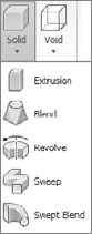
This tool allows you to create a family using solid or void geometry that can be made from extrusions, sweeps, revolves, blends and swept blends. Each in-place model can be assigned a specific category that is later used to control visibility and behavior in the model. For example, assigning the family to the Wall category allows the wall to host inserts such as windows and doors, as well as schedule a wall. Figure 6.28 shows the available modeling techniques for modeling in-place.
For example, Figure 6.29 shows an example of the type of forms you can create using this Swept Blend modeling tool.

Let's look once more at the wall in Figure 6.27, which was created using a series of blends assigned to the wall category. It still behaves as a wall: you can make doors and windows, and they cut through the geometry of the wall as with standard walls. Various wall types can be created using this method.
The beauty of Revit modeling tools is that you can always go back to the sketch and change your base idea (the sketch), and all related changes will happen automatically. You do not need to redraw the profile. The same applies for the sweep path — if you used the sweep technique, you can edit the path at any point while keeping the profile. Figure 6.30 demonstrates various types of irregularly shaped walls created using techniques similar to the ones described before.

The Curtain Wall tool is designed with flexibility in mind. You can use it to generate anything from simple storefronts to highly articulated structural glass façades. In this section, we'll look at the basic principles and how to extend these principles to create a range of designs.
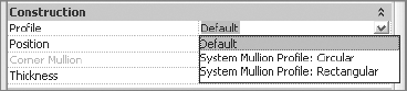
As we mentioned in Chapter 4, "Modeling Basics," the composition of a curtain wall is divided into the three primary elements shown in Figure 6.31 — curtain grids, mullions, and curtain panels — plus the entire curtain wall unit and its geometric extents.

- Curtain wall
A curtain wall is drawn like a basic wall and is available in the Type Selector when you click the Change Element Type button when the Wall tool is active or a wall in a project is selected. It has top and bottom constraints, can be attached to roofs, can have its elevation profile sketch edited, and schedules as a wall type.
- Curtain grid
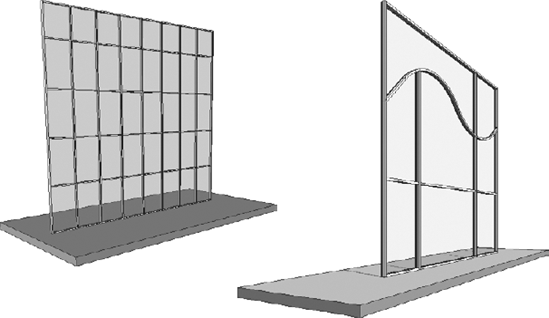
The curtain grid is the layout grid that defines the divisions of the curtain wall facade, which is used to set panel sizes and mullion placement. The layout grid can be designed freely as a combination of horizontal and vertical segments or can be a type with embedded rules that specify regular divisions. Figure 6.32 shows two dramatically different types of curtain wall systems.
- Mullions
The mullions represent wood, metal, or PVC profiles on a glass or any panelized façade, and in Revit they follow the geometry of the grid. They can have any shape that is based on a mullion profile family.
- Curtain panels
The curtain panels fill in the space between gridlines and are always one of the following:
- Empty panels
No panel is placed in the mullions.
- Glazed panels
These panels can be made out of different types of glass that can have any color or transparency.
- Solid panels and panels with wall types
These panels can take on any geometry you wish, allowing the creation of interesting structures like the one shown in Figure 6.33.

Revit provides specially tailored selection options in the context menu to aid with workflow and interaction when working with curtain walls. When you hover over or select an element in a curtain wall, take note of the status bar in the lower left of the screen; it tells you exactly the type of element you're about to select or have already selected. Depending on what the mouse is hovering over, and with the help of the Tab key, you can cycle through various selection options. The elements you can select include the following:
The entire curtain-wall entity (this selection is indicated by a green, dashed line surrounding the curtain wall)
A gridline
A mullion
A curtain panel
To select the element you want, use the Tab key until the element of choice is highlighted.
In this exercise, we'll walk through the creation of a simple curtain wall. To draw a curtain wall, you can either draw a standard wall and then change its type to Curtain Wall, or select the Wall tool and then select a Curtain Wall type from the Wall Type Selector available when choosing the Change Element Type button. Follow these steps:
On the Home tab, in the Build panel, select the Wall tool.
From the Element panel, click Change Element Type and, from the Type Selector list, select Curtain Wall.
In the Level 1 plan view, draw a curtain wall. Use the wall type Curtain Wall 1.
Once you've drawn the curtain wall, press Esc to finish the command, and from the Quick Access toolbar in the top left of the screen, click the 3D icon to toggle the view to 3D.
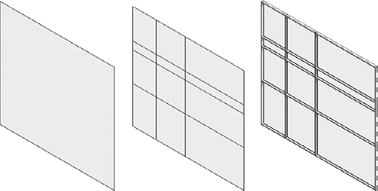
To divide the wall into panels, use the Curtain Grid tool, also available in the Build panel of the Home tab. Mouse over the edges of the wall to get a preview of where the grid will be placed. Revit has some intelligent snapping built into grid placement that looks for midpoints and points that will divide the panel into thirds.
You can then start placing mullions using the Mullion tool located on the Home tab. Place one mullion at a time by selecting separate segments; or, if you want to apply the same mullion on all segments, hold the Ctrl key and click a gridline to select all segments and apply the mullions. The series of images in Figure 6.34 shows the approximate results you should get.
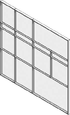
Let's say you want to add more mullions, but this time you don't want them to extend the entire height of the curtain wall. Select the Curtain Grid Line tool, and place new grids as shown in Figure 6.35.

To change mullion types — in this case, the border mullions — use the context menu to isolate mullions for selection. Hover the cursor over a mullion, right-click, and select Mullions → Border Mullions to select all border mullions.
Swap them for another type using the Change Element Type option that appears when you select the mullion. If you don't find a mullion type with the dimensions you need, no worries — it's easy to create a new one on the fly:
Open the mullion's element properties.
Select Edit Type, and then click Duplicate.
Name the mullion type. In the Type Properties, change the thickness to the new value to 8″ (200 mm) and the two parameters for width (this represents half the width of the mullion) to 1.25″ (35mm). Figure 6.37 shows the finished exterior mullions.


The result shows thicker mullions on the border of your curtain wall.
Curtain mullions are usually rectangular, and you can make new types of different sizes on the fly, as shown in the previous exercise. However, not all mullions are simple rectangles. With Revit, you can use complex profile shapes as extruded mullions. Mullion profile families can be made with the Family Editor.
The default library provides some mullions that use custom profiles. To use these, load them into your project, duplicate an existing mullion type, and set the type parameter profile to one of the newly loaded profiles. A list of available profiles loaded into the project appears in the field shown in Figure 6.38.
Note
In reality, curtain-wall mullions can have complex internal details from a manufacturing perspective. Many curtain-wall manufacturers provide DWG details showing the actual manufactured look of the mullions. You'll probably want to show more of those details when you do detailed drawings.
Curtain panels fill the space between the curtain grids or between the mullions. These elements are created in the Family Editor using the Curtain Panels family template. You can create a new curtain wall panel any time by going to the Application menu and choosing New → Family and from the list of Family Templates, select the Curtain Wall Panel.rft. The Revit default project template has a couple of curtain panels preloaded for you: System Panel Glazed and System Panel Solid.
You can duplicate different types of these families and change the material, thickness, and offset to customize the appearance.
By default, Revit applies glazed curtain panels as panels for the curtain wall. Using the method explained earlier, select one of the curtain panels and use the Change Element Type command to open the Type Selector and select System Panel Solid. Your curtain wall panel will look like Figure 6.39.

Curtain walls can host specially designed doors and windows. Keep in mind that standard doors and windows cannot be hosted by a curtain wall. These specially designed curtain wall elements are recognizable by their name, indicating that they are curtain wall doors or windows and that they schedule as doors and windows, but that their behavior is dependent on the curtain wall. Curtain-wall doors and windows adapt their width and height to fill in grid cells. Essentially, they behave exactly like panels — they've just been made to appear and schedule as doors or windows.

To insert a door within a curtain wall, you will first need to load one in your project: in the Build panel of the Home tab, expand the Component button and choose Place a component. From the Model panel, select Load Family. Navigate to the Doors folder, and select a Curtain Wall Door (Single or Double). After loading the curtain door family, tab-select a curtain panel you want to exchange with the door. Then click Change Element Type and select the loaded door family. A door is added to the curtain wall, as shown in Figure 6.40.
Note
Be sure you make the distance between gridlines or between mullions reflect a standard door size. You can do this before or after the placement of the door. The curtain wall is highly parametric, so changes are allowed at any time during the design process.
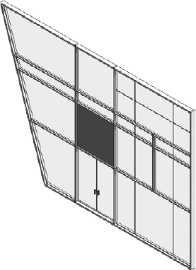
You can edit the profile shape of a curtain wall, just like a basic wall. Select the curtain wall assembly (make sure you cycle with the Tab key until you select the entire assembly represented with dashed lines) and click the Edit Profile button in the Modify Wall panel to start editing the sketch outline of the wall. Follow these steps:
Select the curtain wall you created in the previous steps.
Click the Edit Profile button in the Modify Wall panel. You will be switched to a Sketch mode in which the outer shape of the curtain is represented as a sketch of connected lines. Change the sketch similar to the final image shown in Figure 6.41.
Switch to 3D view.
The resulting curtain wall should look like the one in Figure 6.41.
To prepare for the next exercise, undo this last profile edit.
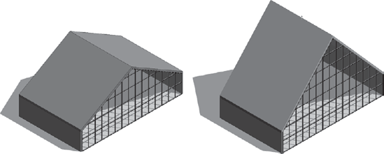
Curtain walls have a highly parametric relationship with other modeling elements. Like a basic wall, when a curtain wall is attached to a roof, it maintains its connection to the roof as the roof shape adjusts. To see how this works, start a new session of Revit and follow these steps:
Draw four generic walls on Level 1, similar to the ones shown in Figure 6.42.
Add a Roof by Footprint on Level 2, picking all four walls with the Tab key. By default all four sides will have slope assigned.
While still in Sketch mode, select one of the sketch lines and on the Options bar uncheck the Defines Slope option for it. Repeat the same for the opposite side of the roof sketch. Finish the sketch. This will generate a gable roof.
Switch to 3D view.
Change one wall to the Curtain Wall: Storefront type by selecting it and clicking the Change Element Type option.
Tab-select all four walls, and attach them to the roof using the Top/Base Attach button located in the Modify Wall panel of the Modify tab.
Select the roof and drag the blue arrow on the top to make the roof pitch higher. The curtain wall automatically readjust its size and shape to accommodate the change, as shown in Figure 6.42.
Note
It's really important to make the wall higher (or lower) than you need and attach it "down" to the roof or "up" to the floor. This prevents hosted elements from getting lost if the wall becomes detached. For example, suppose a 10′ wall is attached to the roof 100′ above Level 1. Windows and other hosted elements are then placed in the wall throughout the elevation. Then someone deletes or modifies the roof so that the wall becomes detached. All the hosted elements are deleted as well. Very bad.
Curtain walls can also use standard wall types in lieu of panels. Using the same method described previously, select a curtain panel and exchange it with a basic wall using the Channel Element Type tool.
Look at the complex-shaped curtain panels in Figure 6.43. You may think, "Oh, I can never do that!" Well, Revit can help you do it — and do it easily. To be fair, you'll need to have some mileage in using Revit before you can create such a curtain wall. But isn't it inspiring to look at all the possibilities that you'll be able to master one day?
The creation principle behind any of these types of curtain walls is the same as we just reviewed. All that differs is the geometry of the curtain panel.
The curtain walls in Figure 6.44 were created with curtain panels that — instead of a standard rectangular solid shape — are made of a solid extrusion that is perforated with four corner openings. An additional solid geometry represents one quarter of the spider clamp. Put all together, it creates a powerful, fully parametric curtain wall!


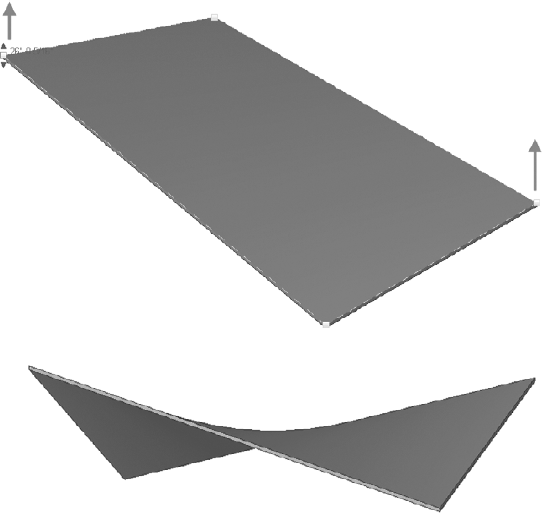
No flat roof is ever really flat! And Revit is equipped with smart tools that allow for tapered insulation over a flat roof and similar conditions. A rich set of shape editing tools for roofs and floors help create and modify such conditions in no time. These powerful tools are modifiers that are applicable to roofs and floors and will allow you to model concrete slabs with multiple slopes, often referred to as warped slabs (see Figure 6.45).


Here is what each tool is meant to do (left to right):
- Modify Sub Elements
This tool allows you to direct edit element geometry using selection and modification of points (vertices) and edges.
- Add Point
This tool allows you to add points on the top face of a roof or floor. Points can be added on edges or surfaces.
- Add Split Line
This tool allows you to sketch directly on the top face of the element, which adds split lines to the floor and roof so that hips and valleys can be created.
- Pick Supports
This tool allows you to pick linear beams and walls to create new split edges at the correct elevation automatically.
As you will see, once any of these modifiers are applied to a floor or roof, a new Reset Shape button appears in the tab. When you click it, this button will remove all modifiers applied to the floor or roof that you have selected.
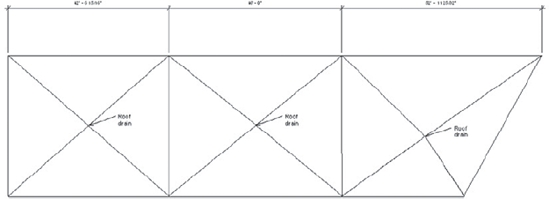
Let's do a short exercise that shows how to make a sloped roof like the one in Figure 6.46 (shown in plan view).
Follow these steps:
Open
Modifying Roof Shape start.rvtfrom the book's companion web page (www.sybex.com/go/masteringrevit2010).Select the roof that has already been prepared for you.
From the Shape Editing panel, click the Add Split Line tool (note that the color of the rest of the model grays out while the roof lines are dashed green).
Sketch ridge lines to divide the roof into areas that will be independently drained. The ridge lines will be drawn in blue color.
Using the same tool, draw diagonal lines within those areas to create the valleys. Zoom in closely when drawing the diagonal lines to be sure that you are snapping in the exact same diving points. (If you notice that you have not snapped well, select the Modify Sub Elements tool, delete the incorrect segments, and try again.)
You have split the roof surfaces into many subfloors, but they are still all at the same height and inclination. You should have a roof that looks like Figure 6.47. Press Esc to stop the editing mode.
Switch to a 3D view.
To add a slope, you need to edit the height of the drainage points. Tab-select the crossing point of the diagonals. New controls that allow you to edit the text appear, and you can either move the arrows up and down or type in a value for the point height. As shown in Figure 6.48, type in –0′ 5″ (−13 cm).
Repeat steps 1–7 for all three drainage points.
If you need to move the point to another position (perhaps to accommodate what's happening in the room below the roof), select the point and drag it, as shown in Figure 6.48.
Make a section through the roof — if possible, somewhere through the drainage point. Open the section; change the detail level to Fine to see all layers. The entire roof structure is now sloped toward the drainage point, as shown here:


Figure 6.48. Drag the drainage points to change their height or type in a new value in the numerical field
What if you wanted the insulation to be tapered but not the structure? For that, the layers of the roofs can now have variable thickness. Let's see how to apply a variable thickness to a layer.
Select the roof, and navigate to its type properties to edit its structure.
Activate the preview. You will notice that in the roof structure preview, you do not see any slopes. That is correct and will not change. This preview is just a schematic preview of the structure and does not show the exact sloping. Look for the Variable column under Layers (see Figure 6.49). This allows layers of the roof to vary in thickness when slopes are present. Check Variable for the insulation material.
Go back to section view and take a look at the difference that this change provoked. As you can see here, only the insulation is tapered now, while the structure remains flat:


Warped surfaces can also be created using this tool. Using the Roof by Footprint method, draw a flat roof (no slopes) and then select the roof. Using the Modify Sub Elements tool from the Shape Editing panel, you can start moving edge points up and down (Figure 6.50).