
Now that we have developed a language for working within Revit, let's look at how you can use it to work and communicate with others. The building industry is a complex organism with many moving parts and participants. Partners, consultants, contractors, subcontractors, and owners are all involved in the process and need the ability to exchange vital design information. Because of the robustness of information within the Revit model, it's possible to do things with data that weren't possible with basic 2D drafting. Even so, data exchange with other applications is still a requirement. Revit provides tools to import and export a wide range of information.
In this chapter, we'll show you how to export your Revit model in forms that others can read and how to import information that is relevant to your project from other sources. We'll first review all the possible export and import file formats, and then we'll dig into more detailed use cases. Topics we'll cover include:
Exporting your data
Exporting DWG drawings
Importing and linking
Working with imported files
Working with civil engineering DWG files
Converting 2D drawings into a 3D BIM model
Starting a new project
Starting a model from a scanned drawing
You can find the Export options under the Application menu R → Export. Revit offers several export formats depending on the format and type of data you want to export.
Here's a list of the types of files that Revit can export using information from the Revit model:
At the end of the Export file list you will also find an Options button—here you will find exporting options relevant to exporting Revit categories to layers (DWG or DGN) as well as an IFC mapping file.
Export CAD Formats lets you export a view or sheet of the model into a 2D or 3D CAD format. The following CAD file formats can be exported directly from Revit: .dwg, .dxf, .dgn, and .sat.
DWG refers to the original patented Autodesk exchange format, RealDWG. DWG has been the established standard for exchange of digital data in the construction industry for the last 20-plus years. Revit can export a part of or an entire project, collections of sheets and views, or any individual sheet or view to the DWG format.
Revit exports views to DWG in two different manners: it exports a 2D DWG drafting format (from a majority of the views) and 3D DWGs (from the 3D views). The 3D DWG exports can be viewed in a 3D environment in AutoCAD or any other application that reads DWG. When exporting to DWG, some of the metadata (property information) of elements is also exported and can be read within AutoCAD.
Exporting DWG files is discussed in more detail later in this chapter (see "Exporting DWG Drawings").
Data Exchange Format (DXF) is an open format for storing vector data supported by many CAD applications. DXF is regarded as a legacy standard and is almost out of use in the industry. However, in some parts of the world or with some strongly established practices, it still finds its use, and for those reasons Revit supports exchange with DXF. If you haven't used DXF files in the past, be careful exporting 3D data to DXF. A file can get very large very quickly!
DGN is the name used for CAD file formats supported by Bentley Systems's MicroStation and Intergraph's Interactive Graphics Design System (IGDS) CAD programs. Note that Revit supports export to DGN file formats only up to MicroStation V7.
SAT stands for Standard ACIS Text and it's a format for ACIS, a solid modeling technology supported by many design applications. ACIS can store modeling information in external files called save files. These files have an open format so that external applications, even those not based on ACIS, can have access to the ACIS geometric model. Revit exports to version 7 of SAT.
The DWFx format allows you to share your project documents with others who do not own or know how to use Revit but need to examine or review your design. DWF files are a way to share rich geometry and metadata while maintaining ownership of the intellectual property in your files. The exported DWF files are small, which makes them easy to email, something you cannot do with a large Revit file.
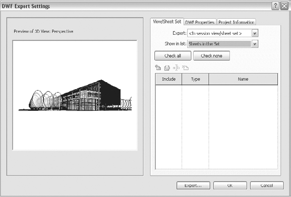
You can export to DWF any view/sheet in Revit, regardless of whether the containing information is 3D or orthogonal 2D views. To export your active view, simply open the Application Menu and choose Export → DWF. The DWF Export Settings dialog box (Figure 7.1) will open and let you choose which views/sheets to export. The default is your current view. After selecting what you wish to export, give your file a unique name and save it. The recipient of the DWF file can then open it with Autodesk® Design Review, free to download from www.autodesk.com, to see the result and make any further comments and markups as you review the files.
You can also publish the exported DWF files directly from Revit to Autodesk® Buzzsaw®, a free, integrated, all-digital way to view, print, mark up, and compare versions of drawings, maps, and models—an on-demand collaborative project management solution for organization of construction-related documents. To access that option, go to the Application menu and select Publish → DWF to Buzzsaw.
Sharing a rich 3D BIM model with other professionals can prove to be problematic because of its complexity and size. Depending on the professionals you need to share BIM geometry and information with, they usually need just a subset of the rich information contained in the BIM model but have little flexibility to control this on their end.
To accommodate this, Revit 2010 has introduced a new smart way of sharing a BIM model made by architects using Revit with civil engineers using AutoCAD Civil 3D software: the BIM model is shared in a way that's simplified and relevant to civil engineers.
With the help of this new functionality, you can export the following types of information relevant to the civil engineers who work on developing the site around your project and need a certain set of information about your building as a context for their work:
Building footprint and its area
Building location
Simplified 3D model
Roof, door, floor, site, and utilities data
Project information
Building with appropriate level of simplicity
The Export Building Site functionality can be found in the Application menu, under the Export Building Site option. To make a meaningful export to a building site, you will need to make some preparations in your model. At a minimum you will need to have at least one gross area defined—the one that represents the building footprint. If you initiated the export to the building site without having defined a gross area, you will be prompted to do so. You should export as little data as possible and choose what will be most meaningful for the civil engineers. For example, there will be many doors in your project, so you will need to assign to the doors a Type property that defines whether they are exterior or interior and then filter out (turn off by type) the interior doors so that you export only the exterior doors to your civil engineers. The rest of the exported information, such as the finished floor height, roof slope and area, and property line information will be reported directly from the parameters of your building elements.
Once you select Export to Building Site, the Building Site Export Settings dialog box opens and informs you about your current export settings (Figure 7.2).

The exported file formats are new to the industry and announce new ways in smart interoperability with applications such as AutoCAD Civil 3D:
Civil Design Exchange File (
.adsk)Civil Design Package File (
.adpx)
It's possible to export any of the views within Revit to an image file. You can also create walkthrough animations and animated solar studies in Revit and save them as .avi files.
To export a Revit view to an image file, open the desired view, and from the Application menu choose Export → Images and Animations → Image.
In the Export Image dialog box (Figure 7.3), many of the options are similar to the other export and printing functions. Export Range, for example, gives you the option to export either the current view or a series of views, similar to the Print dialog box.

The Name field allows you to browse to a path in any of your folder directories to place the image. By default, the image name is the same as the view name. Similar to the options available when printing, you can choose to exclude elements such as crop boundaries, scope boxes, and work planes. This will give you nice results without having to worry about turning categories on and off every time you want to print or export an image.
Revit can export any view or sheet in several image file formats: .bmp, .tif, .tga, .png, or .jpg.
CREATING A BROWSABLE WEBSITE FROM THE REVIT MODEL
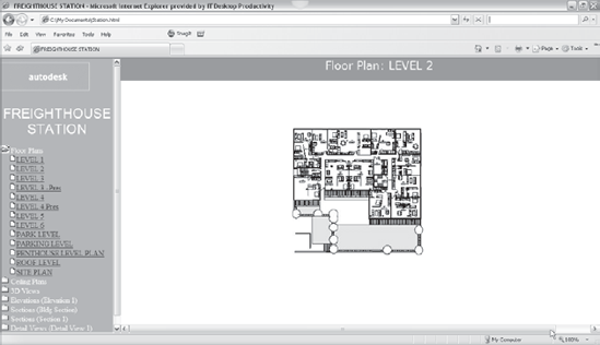
When more than one view is selected for export to image, pick Selected Views/Sheets under Export Range, and an option becomes active in the Output section of the Export Image dialog box that lets you create a browsable website with a linked HTML page for each view, as shown in Figure 7.4.
Revit exports every view as an image and links to them with an HTML file, all packaged neatly into a folder. This allows you (or someone else) to scroll through the project views quickly and easily.
Note
This technique is practical when you create PowerPoint slides for a project presentation and need all views exported in image formats.
IMAGE SIZE
This section in the Export Image dialog box allows you to set the size of the exported image. You can either fit it to specific pixel dimensions or zoom the image to a proportion of its actual size. Keep in mind that this is a proportion of the view size, not the model. So, if your view dimensions are 10" × 10" (25 × 25 cm), and you're zooming to 50 percent, your exported image will be at 72 pixels per inch (ppi) and 5" × 5" (10 × 10 cm), not at 1:2 scale.
FORMAT
This section in the Export Image dialog box allows you to choose your export file type from the list shown earlier in Figure 7.3. It also gives you the option to raise the pixels per inch (ppi) exported from 72 ppi to a higher density. The more ppi, the longer the export time will be, and the larger the final image file. As a general rule of thumb, use 72 ppi for images that will be viewed only on a monitor or screen. Use 150 ppi for images that will be sent to a laser printer and 300 ppi for any image printed by an offset press or when there's a need for high-resolution imagery. Figure 7.5 shows an example of an exported image.

To export a walkthrough, from the Application menu choose Export → Images and Animations → Walkthrough. You'll find the Walkthrough tool on the View tab, in the Create panel under 3D View.
Revit lets you make animated solar studies, and those can also be exported as .avi files. To export an animated solar study, use the same location: from the Application menu choose Export → Images and Animations → Solar Study. Creation of solar studies is covered in Chapter 8.
You can export almost all the information embedded in your Revit model to an ODBC table. Doing so creates a link between your Revit file and another external database such as Excel, Access, FileMaker Pro, or SQL Server. ODBC gives you the opportunity to download data from any of the tables in Revit directly to a database using the Microsoft ODBC connector. An example of this functionality is a cost-estimating software add-on package that gets material quantity take-offs directly from the model.
ODBC is an advanced topic that we won't cover in depth in this book. However, if you do need to export to a database, here's how to use the Microsoft ODBC connector:
Open the file
Station.rvtat the book's companion web page,www.wiley.com/go/introducingrevit2010.Select Application menu → Export → ODBC Database (you will have to scroll the menu down—by default the ODBC Database export option might not be visible as it is at the end of the list).
Click New to create a new data source name (DSN).
Select a driver. This driver will normally be associated with the software program you export to, for example, Microsoft Access, dBase, or Paradox.
Click Next.
Type a DSN name, and, if necessary, navigate to the directory where you wish to save it. Click Next. A confirmation dialog box appears. If any information is incorrect, click Back and correct it.
Click Finish.
Next, create the database file:
Click Create in the ODBC Microsoft Setup dialog box.
Navigate to the directory where you're saving the database, type the database name, and click OK.
Click OK in the confirmation dialog box.
Click OK in the ODBC Microsoft Access Setup dialog box.
You just created a database output out of your Revit model. If you chose Microsoft Access as a driver, you can open the .mdb file you created in Microsoft Access and view the database of all Revit elements in the project.
Revit will let you export schedule tables, view lists, material take-offs, key legends, and note blocks as a tab-delimited text (.txt format) file that can then be read by Excel or any other spreadsheet/database application. Note that none of the formatting created within a Revit schedule, such as column spacing or font style, will be maintained. To export to .txt, open the schedule you want to export, and from the Application Menu, choose Export → Reports → Schedules. To make an .xls file out of it, open the .txt file in Excel and save as .xls.
Room/Area Report is a tool that creates a graphical and mathematical HTML report as a proof of the digital calculation of rooms in your project. Some authorities in Europe and Asia require these area reports as a part of permit documentation. Each room surface is divided into basic geometrical shapes (triangles, rectangles, arc segments), and each shape is described with a name that, in the table, has the geometrical formula used to calculate area.
You have the option to report the window area as a percentage of the room area. To comply with certain standards in different countries, you can choose to exclude columns from the total room area calculations by making your columns non-room-bounding. This is done through the Element Properties dialog box of individual columns.
To create such reports, from the Application menu select Export → Reports →Room Area Report, select the view or project, and define your graphic settings. You'll receive an HTML page of the report. A sample report is shown in Figure 7.6. These reports are not parametrically connected with the Revit model. If you make changes in the model, you will need to re-create (re-export) the report.

The FBX is a widely used and supported platform-independent 3D data exchange platforms. It enables export of a 3D model and all the material definitions, so you can open the file in 3ds Max or other modeling/rendering applications and do more advanced renderings and animations. All the materials assigned in the Revit model will translate 100 percent into 3ds Max.
Green Building XML (gbXML) is an XML data type that was created to support the growing trend of sustainability and green building design. As a data type specific to the building industry, gbXML is an export function within Revit and other BIM applications that allows you to export specific data about a model for the purpose of performing energy analysis and evaluating building performance. A number of different applications are available that can read gbXML-formatted files. These applications are primarily designed around performing energy analysis using the Revit model as a basis. This saves a tremendous amount of time, allowing you to reuse your model geometry instead of re-creating it in another analysis application. Some of these energy analysis applications are Autodesk Green Building Studio (www.greenbuildingstudio.com), Autodesk Ecotect (http.//ecotect.com), and IES <VE> (www.iesve.com). You can find more information on them at www.gbxml.org. (At the time of publication, these URLs are still correct, even though Autodesk bought the products.)
Improvements to the gbXML import in this release of Revit Architecture 2010 are as follows:
Preview analytical model
Isolate individual rooms
Color code analytical surfaces
Review room warnings
Define energy data and project
To export to gbXML, go to the Application menu, choose Export, and select gbXML. The Export gbXML dialog box (Figure 7.7) will open, showing the analytical preview of your model and displaying all settings that are relevant to this export.

Industry foundation classes (IFCs) allow for exchange of intelligent data between architectural and downstream applications, based on the STEP application protocol. IFC is a nonproprietary file format that has been recently resurrected as a possible BIM interoperability standard. The goal is to allow the transfer of information between models that have been created using different BIM authoring packages. More information on IFCs and their current and future uses can be found at www.iai-international.org.
Revit Architecture 2010 supports first-stage IFC 2x-3 certification import and export. Revit also has full (second-stage) IFC Singapore Code Checking (BCA) certification, which is export only. IFC can be imported into any other BIM or CAD application that accepts IFC class files.
Note
If you decide to use the IFC for import or export of data, there are a few items to keep in mind. Although multiple industries have made great advances with the IFC 2x-2 data exchange standards, no IFC file will be as robust as the parent file from which it was created. There will always be some data loss as you migrate your data to a more uniform data type.
DWG is the exchange file standard in the AEC industry and is used by the majority of applications as a data exchange method. We'll review some of the specific options and use cases for DWG exports.
In the majority of cases, you'll need to export 2D DWG drawings for owners and consultants or other engineers who are still not on a BIM platform, are not using Revit, and will work with the file directly or use it as an underlay. Let's review all the options you should be aware of when exporting to DWG.
Select CAD Formats from the Export options, and you'll see a dialog box like that shown in Figure 7.8.
You will notice that the dialog box has two tabs: the View/Sheet Set tab and the DWG Properties tab.
In the View/Sheet Set tab you can manage the sheet sets (add, remove, rename, and so on) or define what exactly will you be exporting. The latter is done in the Export drop-down list (up to this release this functionality was described as Range).
- Export (Range)
The Range box in the Export dialog box allows you to select either your current view or a range of selected views and sheets. If you choose the latter, Revit opens a dialog box showing all of the views and sheets currently in the model. After you select the views or sheets you want to export, you have the option to name and save that selection so you can quickly export those same sheets again later on in the design process.
Click the Export button to select to export to an AutoCAD 2010, 2007, 2004, or 2000 file format (Figure 7.9). After you select an export file type, you have a few additional options.
- Naming
This section allows Revit to name the file for you in a short or long format. Alternatively, you can name it yourself with the Manual option:
- Automatic (Long Specify Prefix)
If you choose the Automatic (Long Specify Prefix) option, the Short format grays out the File Name text box and applies the view name or sheet name (depending on what you're exporting) to each of the exported views. This option activates the File Name text box and allows you to put in a prefix for all the files you export. You can enter a project name, a date, or something else as a prefix.
- Automatic (Short)
With the Automatic (Short) option, you can choose to add a short system-defined prefix or a long user-defined prefix to the export file.
- Manual (Specify Name)
If you choose this option, you must name the exported file, because the Name field will be empty upon selection of this option.
- XREF Views on Sheets
When you deselect this option, Revit combines each view on the sheet into a single file. This option is automatically deselected for DXF files and isn't available for DGN or SAT files.


With this box checked, Revit exports each view on a sheet into a separate file and creates a cross-reference (XREF) to the files. If you're exporting a single view, using this feature won't make much difference, but if you're exporting a series of sheets with a number of views on each sheet, this feature will have a very different effect. In this case, with the box checked Revit exports each sheet as a separate file as 2D vector-type views, and then those separate files are combined via XREF within a parent file. For example, if you start with a sheet with four views on it, five DWGs will be exported. With this option unchecked, the views and parent sheet will be a single file with all of the views in the drawing as blocks. In other words, the XREFs will be "bound" on the sheet.
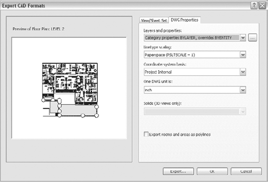
The second tab in the Export CAD Formats dialog box is the DWG Properties tab.
The DWG Properties tab of the Export CAD Formats dialog box, shown in Figure 7.10, gives you some advanced options for exporting to CAD formats:
- Layers and Properties
The Layers and Properties setting determines what happens to a Revit element if it has attributes that differ from those defined for its object style category. In AutoCAD 2010 and in Revit Architecture 2010, view-specific element graphics are referred to as overrides. This option allows you to control how categories are exported and to specify their layer controls. The override options depend on the overrides you've set in the individual views you're exporting. If no view overrides are defined in your exported views, this menu won't change your export.
- Linetype Scaling
This control sets your paper space line type setting in AutoCAD (PSLTSCALE) to either 1 or 0 or scales the line types by definition. This setting ensures visual fidelity between the line type scales used in Revit and those in the exported DWG file.
- Coordinate System Basis
This option lets you choose between a project-internal or shared-coordinate system. It ultimately sets a 0,0,0 point for your CAD file based on the selected coordinate system (either by the internal project 0,0,0 point or by the shared coordinates between multiple project files).
- One DWG Unit Is
CAD packages typically deal with measurements in units, unlike Revit, which builds the model in real dimensions. This menu allows you to correlate export units with Revit data. You can specify the export units: inches, feet, millimeters, centimeters, or meters.
- Solids (3D Views Only)
To export 3D solids, you need to have a 3D view active. Revit provides two types of solid exports: as Polymesh or as ACIS solids.
- Export Rooms and Areas as Polylines
If you're exporting area or room plans, checking this option means that in AutoCAD, the room and area bounding lines will be polylines rather than normal lines (the default option).
In previous releases of Revit, there were some additional options and advanced settings in this dialog box that now have been moved and are accessible from the Application menu under Export, at the very bottom of the list (Options). There you will find the following settings:
- Export Layers DWG/DXF
Revit automatically maps categories and subcategories to preconfigured layer names for export to DWG, and you can see those in this dialog box.
By default, the U.S. version of Revit shows an export list linked to the standard AIA layering schema. If you scroll down this list (see Figure 7.11), you'll notice that you can define the layer name and color for each of the categories and some subcategories of the elements in your model. It's important to point out that this list is dynamic. As you add elements and entities to the Revit model, this list will grow to include them as well as linked and imported CAD and Revit files.
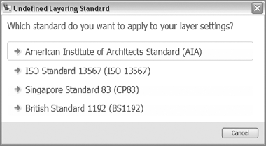
You can access a few preset export layer standards by clicking the Standard button. The predefined standards options are shown in Figure 7.12. Once you've gone through this list and specified the layers to which you want your Revit file to export, you can save the list to a separate
.txtfile to be used in other projects. Alternatively, you can load other.txtfiles into your project that have been exported from other projects.- Export Layers DGN
This option is available only when you're exporting to a
.dgnformat. This means you can include a.dgntemplate file in the exported.dgn. Thus you can export to a MicroStation template file to control the levels at which objects and components export.- IFC Options
Before exporting a Revit project to IFC, you will need to make sure that Revit Architecture supports the desired IFC classes. Use this option to see a complete list of classes.

Now that you know what you can export from the Revit model, let's discuss the types of files you can import or link into Revit.
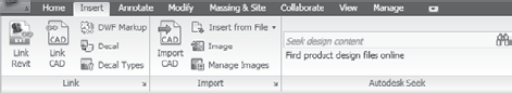
The import and link tools and options in Revit are located in the Insert tab and split between the Link panel and the Import panel (Figure 7.13). You select Import or Link depending of what your intention is and pick the option that corresponds to which file type you are importing or linking.
You can both import and link the following file types:
You can only link the following file types:
Revit:
.rvtfilesLink DWF Markup Set: single- or multipaged
.dwffiles
Note
Revit can read one other very important file format: Industry Foundation Class (IFC) files. Up to this release, one could import IFC files through the File/Import command. In 2010, the location for this has been changed. To open/import IFC in an empty file, go to the Application menu and select Open → IFC.
We'll explore the uses of each of these options. However, before drilling into details, we want to make clear the distinction between importing and linking.
Linking creates a live connection to another file stored somewhere else. This allows you to work on the linked file separately and then have the Revit model update to reflect the changes in the link. This behavior is similar to an XREF in AutoCAD.
The ability to link one file into another can be helpful in a collaborative environment. Perhaps someone on your team—a person working on details within your office or an external consultant—is working in an AutoCAD environment while you build up the project in Revit. Linking lets you have her latest work updated in your Revit model. If you import without linking, you get a static file that will not update. When you link, it's possible to always get the latest state of the DWG by updating the link within Revit.
Switch to the Manage tab and, in the Manage Project panel, select Manage Links. Here you can reload, unload, import, or remove a CAD link or see what is already loaded (Figure 7.14).

You can link other Revit files in your Revit project either for a large campus project where buildings are distributed among separate project teams or for one project that is being worked on by multiple teams in the same office.
When you're working on a campus-style project that contains more than one building, consider making separate models for each building and later connecting them in one file via the linking method. Doing so gives you some flexibility to model individual buildings in individual files without the burden of the rest of the buildings, while still having the versatility to see the campus or building groupings in a file that combines all linked buildings. You can also cut sections or make elevations in which you can see all the buildings or schedule elements across all linked files.
Note
When you're doing campus-style projects, linking optimizes system performance. Working on several smaller files for individual buildings is less memory intensive than working on one large file with many buildings.
Another use of linking is for collaboration in a full BIM project team where the structural engineer is using Revit Structure and the mechanical, engineering, and plumbing (MEP) engineer is using Revit MEP. Using the linking methodology, you can view their models within yours. You can even select and read the properties of the structural or MEP elements from your model, although you can't modify them.
In addition, these three discipline-specific BIM products—Revit Architecture, Revit Structure, and Revit MEP—incorporate tools that let you copy and monitor changes among linked models. This, however, is an advanced topic not covered in this book.
When you link two or more Revit models together, you're linking more than just the model geometry. Linking Revit models allows you to do the following:
View the content of a Revit file that comes from another discipline (such as an engineering drawing of the structure made with Revit Structure or a piping system made with Revit Systems).
Combine scheduled elements of your building in a single schedule, regardless of whether they come from the parent file or from linked files.
Control the visibility of what is displayed from the linked file or imported DWG files in the linked file.
Schedule elements by link instance name so that if an element appears in multiple instances of identical buildings, Revit can identify which instance comes from which link.
Dimension to or from elements and objects in the linked or parent file and establish user-defined relationships and constraints between the two (such as the distance between a property line that is in the main file and the edge of the building that is linked).
Copy and paste elements from the linked to the parent file.
Control and change the visibility properties not only of the linked file but of the nested links as well, without modifying the primary file.
Display nested links (a linked file in a Revit file that is linked into another Revit file) in the host file in two different states: attach and overlay.
Bind a Revit link within the parent model (this is similar functionality to the Bind option in AutoCAD: when using the Bind option, the Revit link turns into a group and becomes fully integrated in the host model).
Copy Revit links across documents.
Display areas and area boundaries in linked files, schedule them, and apply color fill to rooms.
See linked as well as nested links in the Project Browser, where you can unload, reload, open and unload, copy to another level by drag and drop, and access the Manage Links dialog box.
If you've linked a Revit file into your model, you cannot open that link file and start working on it in the same session of Revit. However, if you launch another session of Revit, you can open and edit the linked files. Each session of Revit will show up as a separate application running on your machine.
To link an RVT file, go to the Insert tab and under the Link panel, choose Link Revit. The resulting dialog box looks like Figure 7.15. This dialog is a standard file-open format, with a few options specific to Revit: Open Worksets and Positioning. We'll look at each option and explain what it means.

The Positioning drop-down list provides options for linking the model. You can choose Auto or Manual placement methods, as shown in Figure 7.16.

The Auto placement options will do the following:
- Center to Center
Aligns the 3D center points of both models.
- Origin to Origin
Places the world origin of the linked file at the model's origin point. If the linked model was created far from the origin point, linking with this option may put the linked file far away from the main model.
- By Shared Coordinates
Places the linked file geometry according to the shared coordinate system created between the two files. If no shared coordinate file has been created, Revit will alert you.
- Acquire Coordinates
Allows you to take the coordinates of the linked file into the host model. There is no change to the host model's internal coordinates; however, the host model acquires the true north of the linked model and its origin point.
- Publish Coordinates
Allows you to publish the origin and true north settings to your linked model. Revit understands that there may be other things in your linked file and you may not want this to be a global change to the linked file. An additional dialog box appears that gives you the option to name separate locations for each set of coordinates.
- Specify Coordinates at a Point
Allows you to manually key in X, Y, and Z coordinates relative to the origin point or define where you want your 0,0,0 point to be.
- Report Shared Coordinates
Shows the E/W (east–west, or X), N/S (north–south, or Y), and Elevation (Z) coordinates of any point in the model (see Figure 7.17).
The Manual placement options for links do the following:
- Cursor at Origin
Puts the origin point of the linked model at your cursor location.
- Cursor at Base Point
Puts the base point of the document at your cursor location. This is primarily used for files that have a base point, such as CAD files.
- Cursor at Center
Puts the 3D center of the building at your cursor location.
Worksets are used to divide a model into user-defined groups so that a team of collaborators can simultaneously work on the same Revit project. Worksets can be used to cluster chunks of a building together, and the Open Worksets option lets you choose which worksets to link in. This technique is practical when you're working on big projects where performance may be an issue. By linking in only a subset of a linked file, you ensure that the graphical and memory resources are not taxed as much.
Site plans, consultant files, and details or drawings done with CAD technologies on prior projects all are examples of information you may want to link or import into Revit from a CAD format. This isn't limited to 2D data; you can link 3D files and data as well.
The data you import or link into your model can be view specific (imported and visible in one view only, as opposed to all views), so start by opening the view into which you want to bring data. In this release of Revit, the import and link of CAD formats is separated into two commands located in the Insert tab: the Link CAD command is located under the Link panel, and the Import CAD command is located under the Import panel.
As discussed previously in this chapter, you can link or import five types of CAD files in 2D or 3D in Revit:
.dwgFiles made from AutoCAD or other applications that can export to this standard format
.dxfDrawing Exchange Format files (most software packages write to a.dxfformat)
.dgnMicroStation native files
.satStandard ACIS text files (many modeling and fabrication applications can write to this file type)
.skpSketchUp native files
To import contextual data about the project's surroundings, such as streets and buildings
To import a civil engineering file with your topography
To use CAD detail previously created for another project or directly dragged and dropped from the manufacturer's web catalog
To use Revit to continue a previous stage of the project that you did in CAD, building a 3D model based on the 2D imported CAD file
To work with colleagues who deal with certain aspects of the project in another environment (such as CAD drafters working on details or principals working on massing studies with SketchUp, Rhino, or some other modeling tool)
As explained earlier, there are some pros and cons to each option:
- Linking
If you link a file, any changes made in that original file will be apparent in the Revit file in which it was linked. If your office or team workflow has personnel who are dedicated to working solely on details, they can continue creating and changing the details in AutoCAD, for example, and you can update the link to reflect the changes automatically. You can also manipulate the linked file through the Manage Links dialog box (in the Manage tab, go to the Manage Project panel and select Manage Links).
- Importing
An import is not tied to the original external file, so you can explode the file and modify the CAD drawing directly in Revit. By contrast, you cannot explode or modify lines of a linked import. Once an import has been exploded, the import ceases to exist as a recognizable file but is reduced to lines and becomes a part of the main file. These lines are just that—lines, with no inherent intelligence. You can change their line type, thus changing their graphic appearance.
Regardless of whether you link or import a CAD file, you can always control the visibility of the lines in any view through the Visibility/Graphic Overrides dialog box. For linked files or CAD files that have been imported but not exploded, the lines appear in their own tab under Imported Categories. If the file has been exploded, the CAD lines are integrated into the model (in the case of files not linked with Current View Only) and appear on the Model Categories tab, under the Lines subcategory. If the CAD file was linked with Current View Only, the linework will become detail lines.
Note
One of the primary uses for importing CAD files is to use them as details in the Revit model. If possible, clean up your CAD file, eliminating all the unneeded linework, before you import it into Revit. We suggest cleaning up your CAD details in the native format first and then importing rather than exploding your details in Revit and then cleaning up lines.
The Import and Link CAD Formats dialog boxes are identical and have some additional options to choose from to specify the import/link (Figure 7.18).
- Current View Only
Selecting the Current View Only check box brings the linked or imported file only into the view that is currently active. It's not always desirable to see your CAD files in all the views in your model. More often than not, you'll want to select this check box. Remember, if you import with this unchecked, the file will be visible in all of your views, and you'll need to manage its visibility via the Visibility/Graphic Overrides dialog or with view templates.
Note
Keep in mind that if you do need to see the CAD file in more than one view (but not every view), you can associate the linked file to a workset that is turned off by default in all other views. This will allow you to turn on the CAD file when needed.
Note
If you're importing a CAD file you want to use as a site, make sure you're importing it into all views; otherwise, you won't be able to convert it into a toposurface. It's now possible to convert any solid geometry created in other software packages into a toposurface.
- Layers
The Layers drop-down menu gives you the option to import or link in all the layers, only the layers that were visible at the time the CAD file was last saved, or a selected group of layers. (Layers are a DWG-based naming convention. Revit allows the same functionality with layers from DGN drawings.)
- Layer/Level Colors
The default view background in AutoCAD is usually black. So, the colors used in AutoCAD are easily visible on a black background. When you import a DWG file in Revit, which has a white background, many of the colors usually used in AutoCAD (yellow, light green, magenta, cyan) are difficult to read. Revit recognizes this issue, and in the Layer/Level Colors section of the Import/Link dialog box, it gives you the option to invert these colors into colors that are easier to read on a white background. It also gives you the option not to change the colors, if you prefer, or to convert them to black and white, which is Revit's default approach.
- Import Units
The Import Units drop-down menu lets Revit autodetect the scale at which the imported or linked drawing was created and convert it accordingly. Or, you can apply your own custom scale factor and type it in manually.
- Positioning
This drop-down list is the same as the Revit Link dialog box but with the option to choose what level to place the link at in the Revit model and the option to orient the link relative to the view.
In every project, you'll need to import an image—be it a photograph of the site and its surroundings; background information, such as scanned hand drawings of a historic building; or images that can represent advertising or marketing material (see Figure 7.19).

To import an image into Revit, switch to the Insert tab and, from the Import panel, select Image. Navigate to the appropriate folder, and choose your image file. You can also drag and drop an image file directly from Windows Explorer into a Revit view. Imported images are specific to the particular view you've imported them into.
Once you've inserted the image, you have a few options to edit its size and proportion. Selecting the image highlights the corner grips and lets you resize the image dynamically. Doing so also highlights the Options bar. The Options bar allows you to push the image forward or backward or bring it all the way to the front or back. The Background/Foreground selection tells the image that you want it above or below the model geometry. You can also change the shape of the image by deselecting the Lock Proportions check box.
Once you select an imported image, you can enable the Type Selector by clicking the Change Element Type button. The Type Selector will let you toggle between different imported images just as you would for any component family.
The Instance Properties dialog box shown in Figure 7.20 controls the same element parameters that appear in the Options bar when an image is selected but provides a bit more precision. From here you can set the exact size of the image in project units. Figure 7.20 shows how the image looks when the Draw Order property is set to Background.

You just learned how to import and export drawings with Revit, but now what do you do with them? In this section, we'll explore the use of the various tools used to manage CAD files when they're in Revit.
As we've discussed a number of times, Revit doesn't build the model based on layers like other CAD packages do. Although layers offer an easy way to control the visibility of objects, they're also the reason other software packages can't guarantee quantities. Layers make it possible for an object to be duplicated on many layers and therefore appear more than once in the database. In Revit, every object can exist once and only once. As mentioned previously, Revit uses categories and subcategories for objects that exist in real life and uses annotation elements that describe them to control the visibility of what is presented where.
That may be good, but you work with—and need to exchange digital files with—people who give you information in a DWG layers structure. Therefore, you need to give them layer-structured drawings. Revit can understand imported drawings with layer structures and can also export drawings with a customized layer structure. When you import a file in DWG or other CAD formats in Revit, you can do the following:
Turn layers on or off in imported CAD files
Change the default color of a layer
Delete a layer
Explode a DWG file so you can modify or delete elements from the imported file
Once your CAD file is imported into Revit, either as a link or as an import, you can begin to manage the layers and colors of the CAD objects as they appear in Revit. To do this, use the Visibility/Graphic Overrides dialog box. You can access this dialog box in three ways:
If you import a CAD file into your view, Revit adds an Imported Categories tab to this dialog box. Selecting that tab, shown in Figure 7.21, gives you a list of all the CAD files imported into this particular view. Remember that this list is view specific; Revit changes the list as you add or remove CAD files from the model and from this view.
Selecting the check box next to the name of your CAD file displays a list of every layer present in the file. Use the check box in front of the layer name to control its visibility. Here you can also override the line color and pattern of the layer or turn it to halftone.
Often, you'll need to modify or delete some of the geometry in a CAD file that has been imported into Revit in order to simplify it and prepare it for use in your project. Let's review how this works and all the options available. To start, open the view your DWG is imported into, and click the DWG to select it. Let's take a look at the opened Modify demo and the Import Instance panel (shown in Figure 7.22).

This tool lets you delete an entire layer from the imported file. With the DWG selected, click Delete Layer, and select from the list of displayed layers those you wish to delete. A sample dialog box with its associated layers is shown in Figure 7.23. As with most Revit dialog box lists, you have the option to select all or to select none as well as to invert the order of choices.


The Partial Explode option disassembles the imported file into the first and highest level of entities: blocks, attributes, unassociated lines, arcs, and circles. Blocks remain as blocks and aren't converted to individual lines. In cases where you have blocks within blocks in your inserted CAD file, a first partial explode explodes the drawing, leaving the nested blocks combined. A second partial explode explodes the nested block, leaving the block within that block intact. A third partial explode turns everything into lines.
FULL EXPLODE
The Full Explode option disassembles the entity as well as any blocks or attributes and simplifies it to the lowest level of lines, arcs, texts, and hatches (filled regions). Note that Revit doesn't allow linework or other elements smaller than 1/32" in length (0.8 mm). If you explode a CAD file with line elements shorter than these lengths, they will be deleted.
Note
Given the fact that exploding DWGs can produce a multitude of elements that pollute the database and may affect the performance of the overall application, it's strongly recommended that you consider exploding only when you need to modify the imported DWG. As an alternative, consider using Partial Explode, which may be sufficient to achieve the desired modifications.
The purpose of the Query tool is to find the attributes of individual blocks and layers without having to explode the DWG. After you import a drawing into a project, you can query the inserted object for information about entities contained in the drawing. After you click Query and click an entity, Revit first highlights the lowest-level entities. To select a block within the CAD file, use the Tab key to cycle through your selection options (see Figure 7.24).

Selecting an entity causes the following information about that block or line to be displayed:
- Type
Information about the type of the entity selected (line, text)
- Block Name
The name of the block that contains the entity, if applicable (N/A means "isn't available"; the entity doesn't belong to any block)
- Layer
The name of the layer containing the entity
- Style By
Indicates whether the entity style comes from the layer or is defined by color
These results are reflected in an Import Instance Query dialog box (Figure 7.25).

To find out the property information of the layer or instance, select the DWG, click the Query tool located on the Import Instance panel, and click the object or geometry that you want additional information about.
Once you have this information, you can do two things:
Delete the layer on which that instance belongs
Note
Once you delete a layer, you can't recover it from anywhere unless you use the Undo function or re-import the DWG.
Hide the layer in that particular view
Note
To turn the visibility of a layer back on after using the Hide in View command, choose Visibility/Graphics → DWG/DXF/DGN Categories.
Civil engineering plans are usually rich in data and information, not all of which is needed by architects. Architects constantly need to clean up civil engineering drawings, retaining only the data that is of importance to the architect for display in their drawings. Revit has a great way to import site information created by civil engineers in DWG file format and turn it smoothly into Revit topography.
Cleanup is one of the challenges when you import civil engineering data. DWGs have numerous layers on which different data is placed (roads, utilities, vegetation, and topographic information). You need to know which layers contain the topographic information and select only those when creating the topography.
Another challenge is that the coordinate worlds of civil engineers and architects often differ. Creating a link between the two coordinate systems is important for a seamless workflow. Engineers typically orient their maps to the north, whereas architects either orient them in whatever way is the most practical to work with or lay them out horizontally.
In this exercise, you'll transfer an imported DWG data into Revit and make it into a Revit toposurface:
Start a new drawing (go to the Application menu → New → Project).
Activate the site view by selecting Site in the Project Browser.
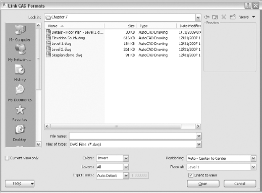
To import the DWG, begin by switching to the Insert tab, and from the Import panel, select Import CAD. Select the file provided on the book's companion web page named
SitePlan.dwg.Make sure you do not select the Current View Only option available in the Import dialog box, and click OK (see Figure 7.26).

Remember that you need to import topography information into the site view.
Note
In Revit versions 9.1 and later, you have to import the site in all views. If you select the option Current View Only, you won't be able to convert the DWG into a topography.
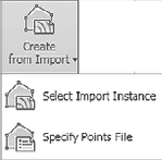
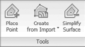
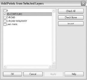
Open the Massing & Site tab, and from the Model Site panel, select the Toposurface tool. From the new content menu under the Tools panel, click Create from Import (Figure 7.27) and then choose Select Import Instance. Click somewhere over the DWG in your drawing area to highlight the site DWG. A dialog box (Figure 7.28) will open, and you'll see a list of all the layers included in the DWG. You need to know the layers on which the topography information is stored and select only those layers. In this case, click Check None, and select the layers called 3D-CONTOURS. Click OK. A toposurface will be generated from the imported geometry. Click Finish Surface to complete the task.
Note
Should you fail to do this and select all layers, Revit will probably fail to create a toposurface.
Note
If you don't have a convention of layer naming with your civil engineer, and you're unsure which layer your contour lines lie on, you can find out by toggling various layers on and off using the Visibility/Graphics dialog box.
After you select the correct layers, Revit will highlight the points on the contours, and your drawing will appear as shown in Figure 7.29.
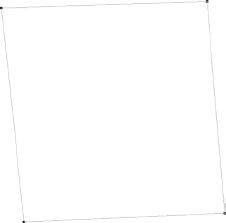
Select Finish Surface from the Create Topography Surface tab. You'll see the image shown in Figure 7.30.


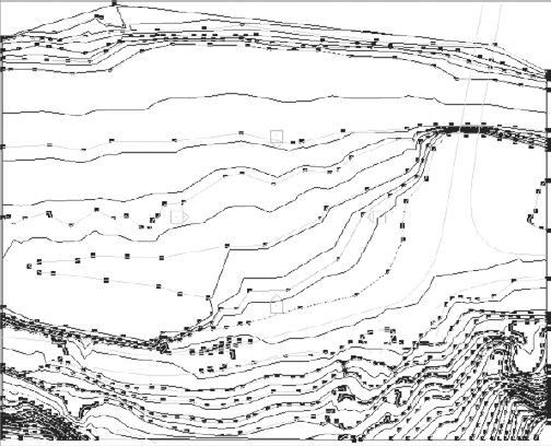
Now, this might be very confusing, as Figure 7.30 doesn't look much different from the DWG you started with. Switch to a 3D view, and activate the shaded view. Now you can see the topography you've created (see Figure 7.31).
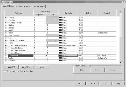
The default material for the topography is Site – Earth, as defined in the Object Styles dialog box shown in Figure 7.32.


If you want to change the material of the topography, select the topography and click the Elements Properties button. In the Instance Properties dialog box, under Material, choose another material (try Site – Grass). The topography will turn green.
If you want to change the default material of the topography, switch to the Manage tab, and under Settings select Object Styles. In the Object Styles dialog box, change the default material for the Site category.
Note
All the site-related materials are listed under Site in the materials table found in the Manage tab, in the Project Settings panel → Materials. In that list, Earth is labeled as Site — Earth, grass as Site — Grass, and so on.
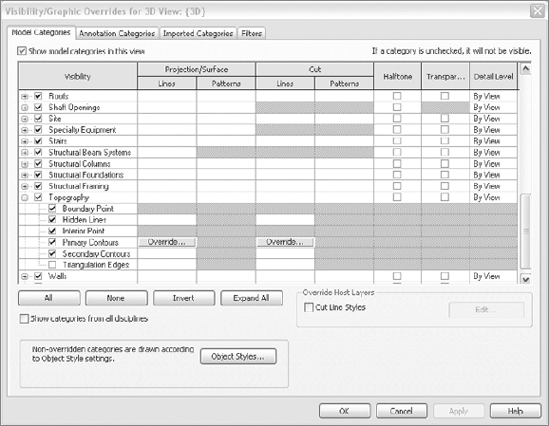
You'll notice that there are many 2D lines on your toposurface that you don't need. Those come either from the contour lines from the imported DWG or from the Revit toposurface primary and secondary contours. Revit allows you to control the visibility of those separately using the Visibility/Graphic Overrides dialog box.
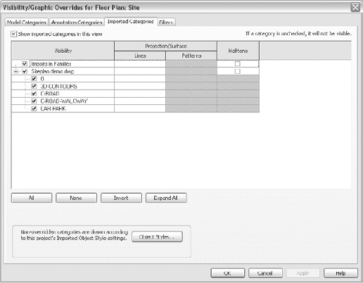
Open the Visibility/Graphic Overrides dialog box, scroll to the Topography Model Category node, as shown in Figure 7.33, and uncheck all subcategories of Topography. You have thus made the primary and secondary contours of the topography invisible in this view.
Now, switch to the Imported Categories tab, and uncheck the entire imported site. To uncheck all the subcategories at once, you can deselect the parent heading, as shown in Figure 7.34. Click OK. Doing this should remove the now-unnecessary DWG line work of the site so it looks much better: You now should see a nice, smooth topography covered with grass.

There are two other ways to create topography in Revit besides using an imported DWG:
You can create a toposurface using an imported points file.
You can create a toposurface from scratch.
You can automatically generate a toposurface based on a points file. A points file is a list of points described with their X, Y, and Z coordinates. It must contain X, Y, and Z coordinate numbers and be in a comma-delimited file format (.csv or .txt). If you receive a points file from a civil engineer, you can view it in Notepad or Microsoft Excel. Here is an example of creating a toposurface from a points file:
To create a toposurface from a points file, follow these steps:
Switch to the Massing & Site tab.
From the Modeling Site panel, select the Toposurface tool.
From the Tools panel, expand the Create from Import button and select Specify Points File.
In the Open dialog box, select the
Points.csvfile from the book's companion web page under Chapter 7. (Note that only.csvand.txtfile formats are recognized.)On the Format tab, set the units in which the points file needs to be imported (see Figure 7.35).
Click the Finish Toposurface button. Figure 7.36 represents an editable toposurface in Revit and the completed toposurface.

Note
Depending on the file you import, after the import you may not see anything on the screen. This means your site is outside of the crop region predefined for the site. To find your site, deactivate the crop region and choose Zoom to Fit All to find the site.

When you don't have any civil engineering data to import and convert to topography but you do have a paper drawing with points information, you can create your toposurface by drawing points and defining their heights. Revit will create a smooth toposurface out of them.
Create a new project and switch to a site view.
Switch to the Massing & Site tab, and from the Create Site panel, click the Toposurface button.
From the Tools panel, select Place Point.
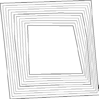
Start drawing points that define your site contour. (Try it with four points to start with, as shown in Figure 7.37.)
Revit closes the points into a loop.
If you don't change anything and just draw four points, all points have the same elevation of zero (Z coordinate = 0). You can give them a height coordinate during the drawing by typing their elevations in the Options bar (

Alternatively, after you've defined the shape in plan view, you can start reselecting and defining elevation coordinates. For the moment, leave the four initial points at 0.
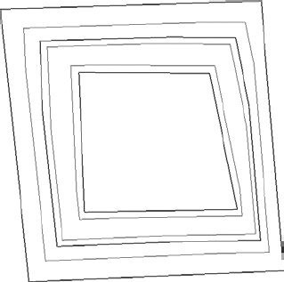
Without finishing the toposurface, draw an additional four points, select them all, and change their elevation to 20" in the Options bar (see Figure 7.38).
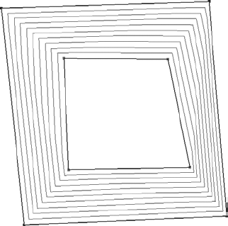
In the Surface panel, select Finish Surface. Revit will grade the distance between the elevations with contour lines, as shown in Figure 7.39. If you zoom in, you'll notice that some lines are stronger and some are lighter. Those that appear stronger are the primary contours. The lighter ones are the secondary contours.
From the Quick Access toolbar select the 3D icon to switch to 3D view, and from the View toolbar activate the shaded view or click the shortcut SD (Figure 7.40).


As with any other preset, you define the distance at which the secondary contours are placed: switch to the Massing & Site tab and expand the Modeling Site panel (click the little arrow on the right of the panel). You will get the Site Settings dialog box shown in Figure 7.41.
In this dialog box, you can also define or change the material that appears in section when the toposurface is cut. It's also where you can control the height in elevation where the base of the toposurface begins to show in section view—if you make a section through the site, you should see what's shown in Figure 7.42.
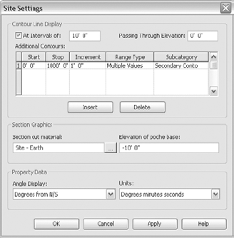

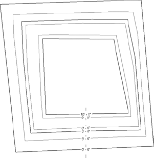
The default settings place the primary contour lines at 10' (3 m) intervals. If you change that to 5′ (1.5 m), you'll see a site similar to that shown in Figure 7.43.
Notice the placement of the secondary contour lines. Revit's default settings place them at 1′ intervals. Change that to 2′ and note the differences in the contours displayed in the model (Figure 7.44).
The contours can also be labeled to indicate their elevation. To label the contour elevations, switch back to site view, select the site and from the Massing & Site tab, under the Modify Site panel select Label Contours (
As with everything in Revit, you can edit the topography at any point later in the process. To do so, select the topography so that it becomes red, click the Edit Surface button on the Surface panel, and modify the site as needed.
All three of the methods described show you how to create a toposurface in Revit. Of course, creating the toposurface is only the beginning. You still have to position your building at the correct location and elevation, create a pad for the building to sit on, and position the parking lot, the walkways, and other contextual features (Figure 7.46). Dealing with site tools, however, is a more advanced topic that won't be covered further in this book.

Often when you are working on a project, you will already have 2D plans, sections, and elevations that you wish to use as a base to create a 3D building information model. Or, perhaps, when you first started to work on the project, you created DWGs. Maybe your firm has just started using Revit, so the project was begun in AutoCAD; or maybe you're working with an existing building created by another architect. In all of these cases, Revit offers you the flexibility to incorporate legacy material in your model.
The development and adoption of intelligent software means that someday redrawing will no longer be a necessity. Revit offers ways to maximize the reuse and referencing of existing data. Converting existing DWGs so they can be used in a Revit model isn't terribly complicated and avoids the need to retrace entire drawings.
You can create Revit objects three ways:
Drawing

Picking references (lines) out of which the object can be created
Picking a face (this is an advanced topic not covered in this book)
These buttons are available in the Draw panel of any element you wish to create. Let's analyze the first two approaches.
The default mode for all Revit tools that require you to draw something is the Drawing mode. You can draw the shape of the object that will be created using standard drawing options.
The second option, denoted with the arrow symbol, is Pick Lines. Instead of manually drawing, this option gives you the ability to create elements by picking references. This means you can pick (and thus convert) any line of an imported drawing into an object. Note that the original line remains available.
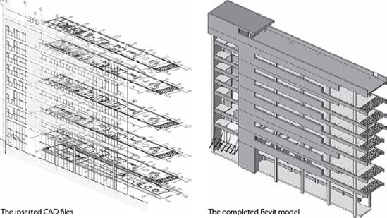
Using a 2D DWG floor plan as starting point for generating a 3D BIM model is best explained using a concrete example, so let's do an exercise. Figure 7.47 shows a series of 2D AutoCAD files set on their corresponding levels in a Revit model and the 3D BIM model created from those plans and elevations.
Here's our strategy for this approach. Import the DWG of each floor into the corresponding level/view in Revit. In the Import CAD Formats dialog box, select the Current View Only option (see Figure 7.48). Note that if you forget to select this option, your imported DWG will appear in every level, and that is not what you want. You want the First Floor DWG to be imported in Level 1 in Revit, the Second Floor DWG in Level 2, and so on. Thus, checking the Current View Only option is very important.
Note
A tip before you start: AutoCAD drawings can be busy, containing a lot of information that isn't always relevant or needed, and this can create visual clutter. When you want to quickly convert them to a 3D model, it helps to turn off the visibility of some of the DWG layers using Visibility Graphics/Imported Categories. Uncheck the layers you don't need, such as dimensions, text, hatches, and so on. Doing so will speed up object selection and facilitate the conversion process.
Start by defining the number of stories (levels) that your building will have and giving the levels floor-to-floor heights. To do this, open a new project, go to any elevation view (let's say south), and modify the project so it has three levels (if you're opening the default Revit template, you'll need to add one level). As we previously discussed, you do that by selecting the Level tool, drawing three levels, and placing them 10′ (3 m) apart.
You are now ready to import some DWGs into the corresponding levels. Follow these steps:
Activate Level 1, and import the DWG Level 1
.dwgfile found at the book's companion web page in theImportsfolder.On Level 2, import the DWG Level 2 file.
Open a south elevation, and import the DWG Elevation South file.
After the import, you may get a notification that none of the imported elements are visible in this view. As previously mentioned, this means the import is somewhere outside the boundaries of the crop region. To remedy this situation, turn off the crop region. Zoom all, and you'll find your DWG.
Reposition the DWG as needed using the Move command.
In the south elevation view, you will need to reposition the levels so that they match the level lines in the DWG import. (Level 1 matches with Level 1-A from the DWG, and so on. If needed, rename the levels to match the naming of the levels in the DWG drawing.)
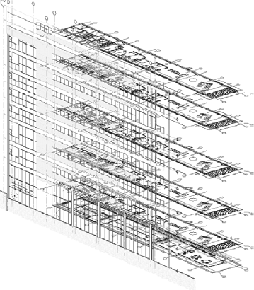
Figure 7.49 shows approximately what the resulting drawing should look like.
Most of the floor plans that you have imported as reference drawings will have gridlines. Generating Revit gridlines from imported lines is simple: in the Home tab, from the Datum panel, select the Grid tool and set the creation method to Pick Lines in the Draw panel. Next, pick any gridline from the imported DWG. Revit will create a gridline on top of the DWG gridline and number it. Revit usually starts with the number 1, but if the DWG grid uses lettered coordinates, you can change the Revit gridline on the first one you create. The remainder will number (or letter) in incremental sequence, so they should append correctly. Otherwise, you can renumber them later.
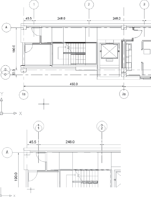
Figure 7.50 shows an imported DWG image. In the second image, the gridlines have been converted to Revit grids using the pick method. Note that the grid bubbles in Revit change dynamically with the view scale. If the bubble sizes don't match, don't panic—just check your scale factor.
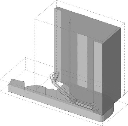
If you have multiple floor plans where the gridlines aren't the same for all levels, you need to use the Scope Box tool. This tool limits the range in which datums (grids, levels, and reference lines) appear, which by default is across the entire project and throughout all levels. Imagine that you have a building with a shopping center on the first three floors and a hotel tower above. The grid systems for the lower and upper parts of the building will be different, and you do not wish to see the grid system of the lower building in the floor plans of the upper building and vice versa. You need to create two scope boxes, assign the grids from the first three levels to one scope box and the rest to the other, and control the area covered by each scope box so they show up correctly. Figure 7.51 shows how scope boxes work in a 3D view.
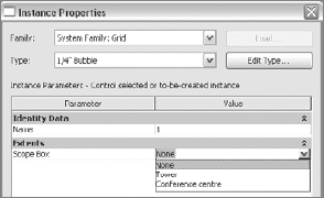
Scope boxes are also visible in 3D views (although not in perspective views), and you can easily manipulate their extent directly using the grips. Assigning grids or other datums to a scope box is easy: select the grids, choose Element Properties, and in the Instance Properties dialog box under Scope Box select the scope box where the datums should belong. Figure 7.52 shows the Instance Properties dialog box for the grids and the associated scope box.
In a 2D CAD application, walls are represented with two parallel lines. You can use one of these two lines as your reference line for creating Revit walls. Create a wall type that is the same thickness as the one used in the DWG. Select the Wall tool and from the Draw menu choose the Pick Lines option when placing new walls, and pick on lines in the import. Be sure to set the Wall Location line to a meaningful value (Exterior Core or Center Line, for example) to get correct alignment.
A rule of thumb when following this creation approach is to set your exterior and shaft walls' top constraint to the top of the building and set your interior partitions to go up only to the next level. If you have repetitive floors with identical or similar floor plans, create the walls once, and then leverage the Copy and Paste functionality to repeat the walls.
Figure 7.53 shows the beginning of a Revit model created using DWG floor plans as a base. DWG wall lines were used as a reference to create the walls with the pick method, and the wall location line was set to the exterior face.
After you create the walls, the next step is to create floors. To create floors, select Floor from the Build panel of the Home tab and select the Pick Lines from the Draw panel. Hover your cursor over the outer edge of the floor or walls and press the Tab key until the DWG floor lines are highlighted. Click to generate sketch lines. If the shape of the floor isn't the shape you want, make corrections using the Edit tools. Remember, a sketch is a line drawing that has to form a closed loop so Revit can create an object out of it.

In Figure 7.54, the lines in the DWG that represent the outer wall faces have been selected, the magenta lines have been adjusted to a rectangular shape (using trim lines), and the floor has been created.
Note
If your workflow permits, draw interior walls before you create the floors so that when you create a floor, it will be attached to the walls and have a relationship with them.
Once you have your wall and floor structure, it's easy to start adding windows, doors, and other elements.

Autodesk's i-drop technology allows you to drag and drop content (drawings) from the Web directly into a Revit drawing. This corresponds to the DWG import process and utilizes Revit's default import settings. From a workflow perspective, it's practical. As you work on your project, you can quickly go to the Web and search for a detail or piece of content in DWG format. Once you find what you need, you can drag and drop it into your Revit file.
Many manufacturers now have their content in i-droppable 2D or 3D DWG format. Figure 7.55 shows some sample i-drop content.

Another source of downloadable library components that can be useful in Revit is Google's 3D Warehouse, which offers files in SketchUp (.skp) format. Revit can read SKP files, and you can import SKP files into an RFA (Revit family file) to create content. These families aren't always parametric—many families don't need to be parametric—because certain manufacturer content exists only in single dimensions and shapes. Figure 7.56 shows some samples of SketchUp content.
The best way to utilize this 3D content is to create a new family (from the Application Menu, choose New → Family) and select a family type, such as furniture or plumbing fixtures. You then can import a 3D SketchUp model into this family. If needed, you can quickly create simplified orthographic projections using the Linework tool instead of using a 3D object to generate those projections. This is useful if you need to show simplified versions of the 3D object in plan, elevation, or another orthogonal view. More details about family generation are covered later in this book.
You can learn more about 3D Warehouse at http.//sketchup.google.com/3dwarehouse.

There are various ways for an architect to start a project. We have reviewed two of them: starting from scratch and starting from an available 2D digital document (CAD file). However, you may have old paper documents of the building that you need to work on.
This happens a lot on smaller projects, usually restorations or additions. Architects may get a few floor plans and elevations that they need to redraw before starting a new project. Let's review how you can use them as a basis to begin a new project.
You start by scanning the floor plan and importing it into Revit as an image in the level relevant to the drawing. Any of the image types we discussed earlier will work fine for your scanned image. An example of a scanned floor plan is shown in Figure 7.57. Follow these steps:
Import and position the scanned image into the appropriate level or view. So, if you have a first floor plan, insert it into your Level 1 view.
Scanned images are usually never perfectly orthogonal, so you need to rotate the image to square the lines of the walls. Use the Rotation tool from the Modify panel, and try to rotate the image as close to orthogonal as possible. To do that, select the image, click the Rotate button, and rotate the image. The rotated image is shown in Figure 7.58.
You need to verify the drawing scale or adjust the scan to fit the scale you're working in. To do so, zoom in on the image, and find at least one wall that has a dimensioned length. In this example, the original drawing was done in metric units.
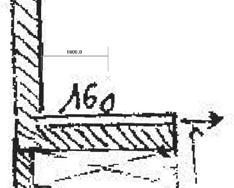
Still with the image selected and using the Scale tool (

Click the wall and then across to the right to the end of the wall. The wall length in the scan is 160 cm and measures 3,200 cm in the drawing. Bring your mouse back to the left, and watch the temporary dimension numbers get smaller (as shown in Figure 7.60). When they reach 160 cm, click again, and your image will be resized.
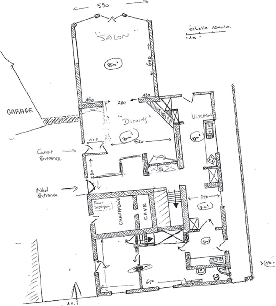


You can now start tracing over the imported image and create the framework for your project. Obviously, scanned drawings can never result in total accuracy, so you'll probably want to field-verify your dimensions. However, this is a good way to get started. Figure 7.61 shows the project with all of the new walls located over the scanned image.
You just scaled the drawing. If you dimension the piece of wall, it should show 160 cm.
Once you've finished referencing the scanned image, you can delete it or hide it in the view.
