This chapter touches on three topics in Revit that are beyond the basics. These topics are explored in more detail in our Mastering Revit Architecture 2010 book (Sybex, 2009), but knowing the fundamentals about them early on can be useful as you gain more experience with Revit.
In this chapter, we will review the basics of the Family Editor, the power of the Design Options toolset, and how to implement worksharing across a team. The Family Editor allows you to create and edit components in Revit. The Design Options tool lets you make design variations and alternatives within the same project in Revit. Worksharing enables you to divide Revit's logical building model in a way that allows more than one person to work on it simultaneously. Topics we'll cover include:
Understanding families
Using design options
Worksharing — the multiuser environment
In Revit, components and other content are referred to as families. Some of these elements can be created and edited on the fly within the project environment, and some are created and edited outside of a project file. Revit comes with a built-in family-editing application called the Family Editor that is tailored for making all types of content, from doors and windows, to annotation symbols, to stand-alone furniture. Creating your own digital library content is a critical aspect of working on projects, and thus creating families is a critical aspect of working with Revit, because families make up a vast amount of what goes into a model and you cannot expect the delivered library of elements, regardless how rich, to cover all you ever need or wish to design.
Unlike in many other software packages, custom content creation in Revit does not require knowledge of any programming language; however, creating and editing of content is still something you have to sit down and learn properly, and something that you can master only after practicing making many families. The process involves using geometry, understanding and establishing constraints, and adding parametric variability into your components. Those topics do not belong in an introductory book and can't be covered in one chapter, but we will explore the very basics of them so that you can at least get started.
All elements in Revit are considered families. When you open Revit, a standard set of architectural objects and annotation symbols is already created and ready to use. These are all "families." Families can be accessed a number of ways:
In the Project Browser Families node, where you can find all loaded families in the project.
In the Type Selector, invoked when using the Change Element Type tool available on the Element panel of the Modify tab when you select any element or the Element panel of the Place contextual tab that appears during creation of any element.
By choosing Load Family, which becomes available during creation of elements when you select certain elements on the Home tab. Here you'll find all the available default families that exist outside the project, in an external library that you can load in the project. You can also browse from this location to any custom location where you have saved families that you've created.
At
www.autodesk.com/revitarchitecture. Under Related Information, select Product Download and then click Templates & Libraries. You can download thousands of families created for different geographic regions.
Revit uses three types of families:
System families (the majority of which are hosts)
In-place families
Component (standard) families
We'll discuss these next.
System families are created in the context of a Revit project on the fly. The only way you can create a new type of system family is by duplicating an existing family and then changing its properties. Here is a list of some of the families that fall into this category:
Walls
Roofs
Stairs and Railings
Floors
Ceilings
Ramps
Mullions
Topography
To create a new system family, select the one that is most similar to the one you need, duplicate its type, rename it, and modify it. Let's use a wall as an example:
Activate the Wall tool. From the Element panel of the Modify tab, select Change Element Type. This invokes the Type Selector, from which you can select a wall that has similar properties to the wall you need to create. If none is similar, it's easiest to use a Generic wall.
Click the Element Properties button to open the Instance properties of the wall, click the Edit Type button, and then click the Duplicate button.
You're prompted to give the new wall type a name. Rename the wall to reflect your design intent.
Start editing the wall by clicking the Edit button under Structure. Doing so opens another dialog box where you can add and modify layers of the wall structure. Don't forget to activate the preview of the wall on the left side. By clicking the fields for Function, Material, and Thickness, you can change the values (see Figure 13.1).

In-place families are the right approach when you are modeling oddly shaped elements that cannot be modeled with their standard tolls (wacky wall shapes, irregular organic roof shapes, etc.) These types of families are built in the context of your project using the Component button available on the Build panel of the Home tab and then selecting the Model In-Place option. This allows you to model geometry that represent a special case of some element directly in the project, using elements in your project as a reference. These families are useful for one-off objects that are highly specific to your project and unlikely to be reused in other projects or in the same project (in which case you should make a component family instead). Usually they are connected with some complex geometry or have complicated shapes, or are tightly coupled with specific geometry in your project and need those references to be created.

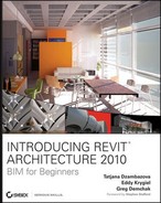
The list of available categories you can assign the geometries to is a fixed, noneditable list — if no category maps to what you intend to create, use the Generic Model category. For example, if you are creating a custom fireplace, you will not find a Fireplace category in Revit; in that case, use the Generic Model category.
As soon as you make a new in-place family, you will be asked to choose your category, as shown in Figure 13.2. You can always change the category later, if need be, by selecting the family you created, selecting Edit In-Place, and then clicking the "Category and Parameters" option available in the In-Place Properties panel. This will return you to the Family Category and Parameters dialog box where you initially set the Wall category, and where you can choose a new one.
The in-place family is good for creating nonstandardly shaped element types such as slanted and tapered walls that you cannot create with the standard wall tool, unusual roof shapes, furniture, or other building elements that must conform to specific geometry in your model (a bench along a curved wall, for example). Figure 13.3 shows an in-place wall that follows the shape of a site and has a nonorthogonal profile.
Having said all that, our advice is to try to use in-place families sparingly. Duplicating an in-place family makes unique elements within the model. If an element is becoming repetitive, it should be replaced with a standard family and created in the Family Editor.
Component families, also called standard families, are created and can be modified in an environment outside the Revit project, called the Family Editor. The fact that these types of families aren't created directly within the project environment allows some diversification of the project workflow and can help to minimize the number of users working directly in a project file on large projects.
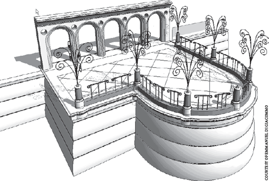
Examples of component families are doors, windows, furniture, plumbing fixtures, light fixtures, entourage, columns, annotations, title blocks, massing families, structural elements, electrical equipment, site equipment, plants, profiles, and so on. Some examples are shown in Figure 13.4.
You will periodically need to open the Family Editor to create a new family. To do so, go to the Application Menu and select New → Family. Often, however, you are working within a project and need to change a family already inserted into that project. To edit a family that is being used in your project, select the family, and then click the Edit Family button in the Family panel of the Modify tab. You'll find yourself in the Family Editor environment, where you can make any change to the family in question.
Because this is an introductory book about Revit, we can't explain the Family Editor in detail (it deserves an entire, separate book), but we would like to explain its basic principles. The Family Editor is designed to do two primary tasks:
Create a new element (family)
Modify an existing element (family)
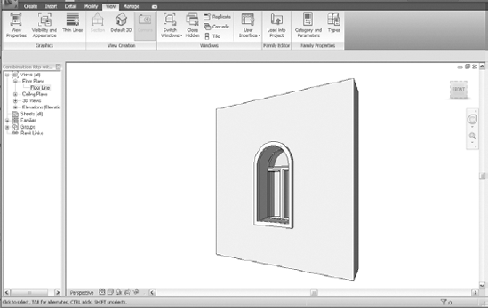
The Family Editor is a unique design environment (see Figure 13.5), but it isn't separate software that you have to install. It's an integrated application that is automatically installed when Revit is installed. The Family Editor resembles the Revit project environment but is tailored for specific tasks and contains only tools relevant to creation of custom elements.
You can open the Family Editor several ways:
When editing a family directly from within a project, using the Edit Family option after having selected an element in the project
By clicking the Application menu and selecting New → Family (to create a new family) or Open → Family (to open an existing family)
When you create a new family, you're prompted to select a template. The templates are predefined files that are set up for the purpose of creating specific content that will behave according to the characteristics of the element to be created. For example, the window template looks different from the door template. The next section discusses templates in more detail.
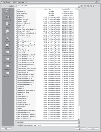
If you're creating a dining table as an example, you need to start with the furniture template. If you wish to create a sink, you start with a plumbing fixture template. To create a new door, select a door template. You get the idea. The available templates for creation of custom elements are listed in Figure 13.6 and can be found in your Libraries folder, located at C:Documents and SettingsAll UsersApplication DataAutodeskRAC 2010Imperial Library or C:Documents and SettingsAll UsersApplication DataAutodeskRAC 2010Metric Library.
The family templates are grouped in four categories:
Model templates (the one you see listed when you open this dialog box)
Annotation family templates (tags, keynotes, and so on)
Concept Model templates. These are new to Revit 2010 and serve as templates to create Conceptual Mass families.
Title block families (you can create custom title blocks per project or company)
Selecting a correct template before you create a family is essential for correct behavior of the element to be created. A correct template does the following:
Categorizes the family you create. This ensures that your family is located in the Project Browser and has a graphic appearance that's consistent with other elements of the same category.
Lists that family in the correct Type Selector when elements are selected.
Schedules the family according to the type you selected.
Enables content-specific parameters and behaviors.
Note
The family templates are different for metric and imperial content. Make sure you select the correct ones when you install Revit.
If you want to create a window but by mistake you choose the door template to start with, your window won't have the parameters necessary to interact properly with the model. If you wish to create furniture but you select a generic family template, your furniture piece won't schedule when you schedule your furniture, and so on.
Note
Rule number one: Decide whether the Family you wish to create will be a hosted or nonhosted element. Try to use hosted geometry only if the geometry you are hosting to needs to be cut for documentation purposes. Examples of this would be windows or doors.
Rule number two: Select the correct template. In most cases, you'll be able to change the family category later.
Rule number three: Choose a good insertion point. The default insertion point of a family will be the center of the green crosshairs that appear in the family template.
If none of the categories match what you're hoping to create, use the generic family template.
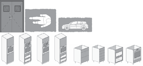
Templates are provided for each category; some additional family templates are also provided. Depending on the type of element, you'll notice that some templates are host based. (Light fixtures can be wall based, ceiling based, and so on.) Make sure you select the one that will make your element behave appropriately. Figure 13.7 shows some hosted families.

Note
You can, if necessary, change the family type after the creation of the family. To do that, open the family in the Family Editor and select the Categories and Properties button located in the Family Properties panel. There, change the family to a new category. This will categorize your element correctly for scheduling.
You can create 2D and 3D families in the Family Editor. They can be either parametric or nonparametric.
Parametric families allow variation in size and material to be captured and edited as parameters. Many types of parametric variations can be stored in a single family as types.
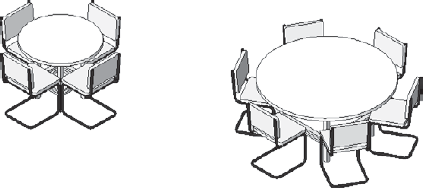
An example of a parametric object is a table that is produced in four different sizes and two different wood types, or a window that is manufactured in 20 different sizes. Figure 13.8 shows a parametric family in two different sizes: as the family is changed, the table size and chair count increase or decrease.
Nonparametric families do not provide changeable dimensions; they may provide variation in material, if anything. An example is a furniture family that is produced in only one size (such as Le Corbusier's "Chaise Longue" or a designer lamp). You can't buy it in other sizes, and thus there is no need for parametric properties. Note that you can make any family parametric at any time by adding a parametric dimension to it.
Nothing in the family template limits a family to being nonparametric. Figure 13.9 shows Le Corbusier's famous Chaise Longue as a perfect example of a nonparametric family.

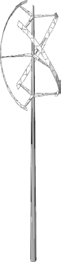
A possible scenario for nonparametric families can involve using content previously made with other software applications and importing it into the Family Editor. Revit allows you to import 2D as well as 3D DWGs coming from any drafting or modeling applications as well as SKP files (SketchUp files). Revit reads these file types, and you can leverage them to extend your Revit library with elements you've created with other software packages. Figure 13.10 shows an imported wind turbine that was built in SketchUp and imported into a Revit family. It can be placed in your Revit models like any other family, with one exception — you cannot control faceting or the level of detail. If it's a complicated family, it's probably best to create it starting in Revit.

Families in Revit let you control the visibility of their individual parts based on the view's detail level. (You can change the detail level in the model using the View Control bar.) When you're working in the Family Editor, you can select any element and choose Visibility Settings located in the Form panel of the Modify tab. The Family Element Visibility Settings dialog box (Figure 13.11) allows you to change the elements' visibility using three levels of detail: Coarse, Medium, and Fine. If all levels of detail are selected, then the element appears all the time, in each possible level of detail. You can also make elements appear in different types of views: plan, front/back, and left/right. Elements are always visible in 3D views, provided all levels of detail are selected.
If you make a simple table or a chair, you'll probably view the table as a simple rectangle in all three levels of detail. If you make a door family, however, you'll want to change the display at different scales. Figure 13.12 shows the three levels of detail. Note that the table doesn't change; the walls get two different representations, and the door has three.

Revit families are flexible: you can choose to display only certain elements of the family in one level of detail and a more complicated presentation in another. It's up to you — you have full control.
The Family Editor allows also for the creation of family types. Family types are best applied to objects created by manufacturers that come in a variety of standard sizes and finishes. Rather than creating 60–70 separate families that are the same shape and material but have many dimensional variations, with Revit you only need to model one family and create type catalogs for each variation. You can then add these types to a type catalog (a simple, comma-delimited .txt file) that makes types of that family, as shown in Figure 13.13.
Once the family is loaded into the project environment, you can select all available types by selecting the Types button in the Family Properties panel.
You can design Revit families that use simple mathematical formulas to determine rules of behavior. For example, a shelving family can be set up so that when a shelf span is longer than 20" (50cm), it gets another support, as shown in Figure 13.14.
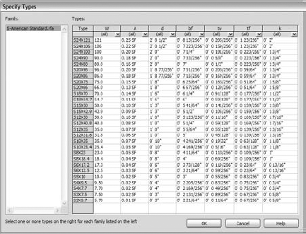
Figure 13.13. A family using a type catalog that contains all variations in which that family is manufactured
All the different family templates let you use custom fields and formulas, so there is no limit to what you can create.

Each family belongs to a category, but you can create additional subcategories in the Family Editor to provide a richer set of controls over the visual and graphic appearance of geometry in the family. A door family, for example, can have several meaningful subcategories: door leaf, handle, hardware, opening direction, frame, and so on. You can control visibility of each of those subcategories by selecting and deselecting them.
Revit lets you combine multiple families into one family. Imagine a door that incorporates a fixed transom window above it. These can be created as two separate families initially but combined into one to be inserted into the project. Nesting one family into the other, rather than using two, simplifies placement and design management in the final project. Revit also allows you to match the parameters of both of the families, so that when you change the width of a door, the width of the transom window (that was nested in the door family) changes, too. Figure 13.15 shows a door with a nested transom: rectangular and arched. An additional dependency between the respective widths has been established. Both are separate families combined into one family.

Figure 13.15. Door transom family nested in a door family. An additional dependency between the respective widths has been established.

Figure 13.16. When dependencies are established, nested families change together with the host (width change in this case).
When dependencies are established, nested families change together with the host. Figure 13.16 shows the dependency of the width of the door and the transom; any changes to one apply to the other automatically.
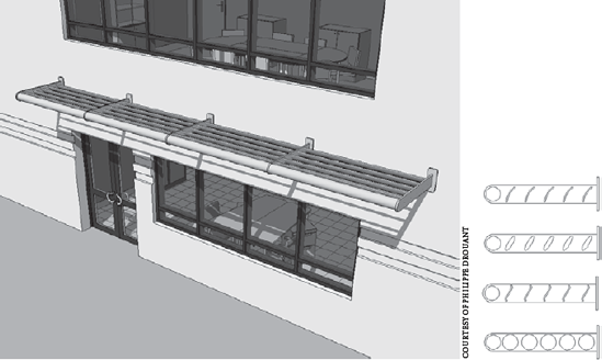
All these behaviors are defined by you, the user. No other software lets you do this without knowing some form of programming language. Similar to the previous example, Figure 13.17 shows a two-pick brise-soleil family with exchangeable lamellas that are nested.
The Family Editor also supports shared families: one family that repeats as a nested family in many different families (a handle can be used on various types of doors, windows, and so on). These families can be shared so that when one changes, all others change, regardless of the host in which they're nested.
The Revit Family Editor allows for creation of very complex families, from both a geometrical and a behavioral aspect. Figure 13.18 shows some complex nested families that you can create in Revit.
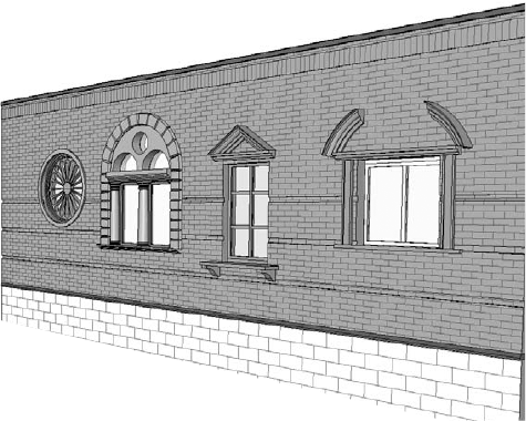
Historical architecture is no challenge for Revit; extremely complex content has been created using the Family Editor all around the world. Figure 13.19 shows an example of some historical windows.

Regardless of which version of Revit you use to create families, you can always open them in a version that is the same or higher. Revit automatically upgrades families from previous releases. Note that once a family has been upgraded and saved, you can't reopen that family in an older version of Revit.

Design iteration is an integral part of a design process, and as architects we're all familiar with the need for and importance of working through multiple solutions and design variations. Design alternatives, schemes, options, versions — whatever you may call them — happen throughout the life of a project. During initial feasibility studies, deciding how to best orient functional program elements relative to the site is common and often involves myriad schemes. Comparing and estimating cost becomes a key factor as well. For each proposal, what is the associated cost? For example, when you move into a more detailed design and want to iterate through a series of entry-canopy options, countless sketches and ideas are processed, and the ability to visualize and analyze multiple solutions is essential to making decisions. Regardless of the stage in the process, you often need to create several design variations.
A typical method for making multiple design schemes, if you're working with a legacy CAD application, is to create one initial design and then make copies of it. Each copy becomes a separate file that is used to explore an alternate design solution independently. Although this approach can work well initially, the downstream effects can be difficult to manage. Integrating ideas from one file to another, maintaining a common set of references, and even something as mundane as file-naming schemes can be tedious and error prone.
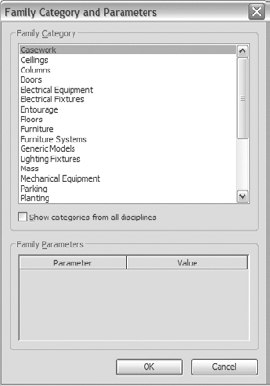
Revit has a tool specifically designed to address this problem: Design Options. An example of use of the Design Options tool is Figure 13.20, which shows variations of balcony solutions for the same residential building.
The Design Options toolset is available in the Manage tab, in the Design Options panel. Figure 13.21 shows the available Design Options toolset.
Because this book is an introduction to Revit, we won't go into the use of design options in depth, but we'll cover the principles behind this tool. Let's briefly explore a scenario for design options. Let's say you need to create various schemes for laying out interior partitions and desks in an office. You want to make two options, which are shown in Figure 13.22: an area with private offices and an open office plan.

It's possible to create both of these options in one Revit file and do so in a very intelligent way so Revit will understand that these are options and not double or triple instances of elements to be counted in the database. You can move elements from option to option on the fly. You can also generate views that show the two options simultaneously for comparison and place these views on sheets to present them for review. You can even schedule each of the options for economic review. Here are some steps describing a design options workflow in Revit:

To create a new option set, click New in the Option Set section of the dialog box. Option sets control subsets of options. For example, if you want two different entry canopies, the option set will be for entry canopies, and the options will be for Canopy A and Canopy B.
Using the Rename button, name the option set Canopy Alternatives.
Using the New button under the Option section of the dialog box, create two options: Option 1 (which you rename as Canopy A) and Option 2 (Canopy B) within the Canopy Alternatives option set. Your option set and options should look like Figure 13.23 when you're finished.
Click Close to exit the dialog box.
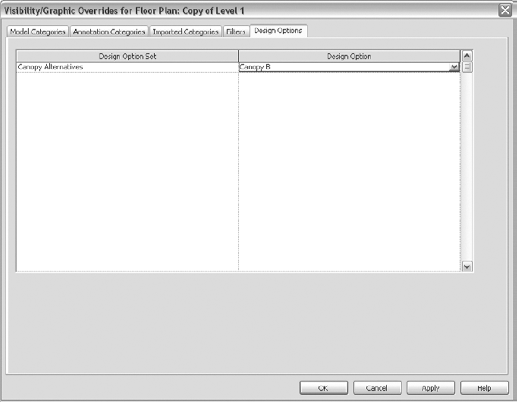
Next, create a duplicate view for comparison. Duplicate any view, and then select the View tab. In the Graphics panel, click the Visibility/Graphics button to open the Visibility/Graphics Overrides dialog box. You will see a new tab, Design Options — select that tab. Change the Design Option setting from Automatic to Canopy B.

Note
You can make as many option sets with as many options in the same model as you need.
You can customize each view to show different design options. Note that only one option from each option set can be viewed at a time. Once you've created design options, a new Design Options tab shows up in the Visibility/Graphic Overrides dialog box of any view. From here, you can specify which option you want to appear in that view. To have the same view type show two different options, you must duplicate the view and in the Visibility/Graphic Overrides dialog box change the design option that you want to display. Figure 13.24 shows the option sets in the Visibility/Graphic Overrides dialog box.
By default, the first option you created will be set to Primary, and that will remain so unless you specify otherwise. To change the primary option, open the Design Options dialog box, select an option on the left, and click the Make Primary button on the right side of the dialog box. So, if the first option you created is Canopy A, then that will be the primary option and this option will be displayed automatically in each view. To change the option you want displayed by default in a view, you can change which option is primary. To see secondary options in a view, use Visibility/Graphic Overrides and change from Automatic to whatever option you want to see.
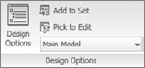
To add elements to an option, click the Main Model button in the Design Options panel, and select the option you want to work in. Figure 13.25 shows these selections for the example we've set up.

Once you're in the proper view with the correct option set and visibility selected, you can start designing for that option. You can tell when an option is active for editing in two ways:
You can't select elements outside the option set.
The Main Model button changed to the design option that is active and displays Canopy A (primary)
Note
In practice, you'll probably start with one design and then realize you want to study some iterations of an element of that design. As an example, let's consider a canopy. If you've already modeled a canopy but you want to study some design iterations on it, you need to create design options. When you do, be sure to move the current canopy design to one of those option sets. If you don't, you'll see multiple canopies overlaying each other in your views.

You may want a quantity overview showing how much material one option uses versus the other. You can generate a schedule that reports information about elements in each specific option. To define what the schedule reports relative to what is visible in the model, edit the visibility of the schedule. In the Instance Properties dialog box of a schedule, click the Edit button to open the Visibility/Graphic Overrides dialog box.
Note
Revit won't report double or triple entities of all options for quantity calculations. It reports quantities for only one design option at a time.

Once you've made a final decision on which option will be the one built, you will need to do the following: first, make the option with which you want to continue the design a Primary option (see Figure 13.27). You can do this by selecting the option on the left and clicking the Make Primary button in the Design Options dialog. Second, and very important, you will need to click the Accept Primary button. Keep in mind that doing so will eliminate all the other options from the Revit project permanently and will merge your chosen option back into the model.
Most projects involve more than one person working at any given time. Often, many people work in tandem to meet deadlines and produce construction documents. Keeping with the theme of an integrated single-file building model, Revit allows for this workflow without breaking apart the model. A complex model can be edited by many people at once using what is called worksharing.
There are various ways that you can share work across a team with Revit:
File linking
Borrowing elements
Worksets
We covered the idea of linked file-sharing methodology in Chapter 7, "Working with Other Applications."
In this section, we'll focus on the other two methods of sharing: borrowing elements and using the worksets methodology.
This methodology allows team members to work on the same file and take ownership of elements to work on. When elements aren't taken by anyone, they're free to be taken and then edited. When a team member needs to work on an element that belongs to someone else, that member gets a message that the element belongs to someone and can then send a notification to the current owner of the element requesting access. The owner of the element can then grant permission to take ownership — relinquishing elements, as it's called in Revit.
A workset is a collection of building elements (floors, roofs, walls, windows, and so on) that can be edited by one team member at a time (if the whole workset is checked out) or by multiple team members (if only individual elements are checked out). You need to understand some core concepts about worksharing before you begin.
Note
Once you enable worksharing in a model, you can't undo it. Remember that. We suggest that you make a copy of your file before you enable worksharing so you keep an unshared version as a backup.
By default, worksharing isn't enabled when you start a project. You share your work by first enabling worksets, then creating a central file. Each user then navigates to the central file and creates a local copy by dragging and dropping the file to a location on their local computer. All work is done from this copied — but still associated — local file. This enables every user to open his or her own file simultaneously. The elements in each separate file are tied to an ownership rule managed by the central file, making it impossible for you to edit an element in your local file if that same element is owned by someone else.
Revit is a database. In effect, you're taking permissions of one or more elements from the central database file and copying changes (and permissions) to the central file. If one user has ownership over an element, no other user can edit that element until its permissions and changes are reconciled with the central file.
Worksets also let you put collections of elements into a container, which is useful for turning off the visibility of elements that aren't being worked on, or for "closing" parts of the model that you're not working on. When you enable worksharing by clicking the Worksharing button on the Collaborate tab, a new tab will appear in the Visibility/Graphics Overrides dialog box for the worksets (view). You can turn on or off any workset in any view and make those settings part of your view templates.
The other team members can view the elements of any workset but can only edit them using element borrowing.
Worksharing is designed to accommodate any division of labor you see fit. There are no inherent restrictions on how you use worksharing to accomplish work. For example, if you want to break up a team and have one group work on the exterior shell and one work on the interior core, this isn't a problem. At any point in a project, you can create or remove worksets.
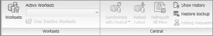
The Worksharing tools are located on the Collaborate tab. You can start worksharing by clicking the Worksets button shown in Figure 13.28.
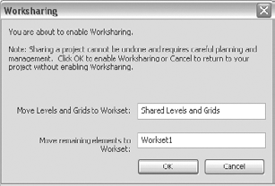
When you click the Worksets button, a dialog box (Figure 13.29) opens, confirming that you're about to enable worksharing and informing you that what you're doing can't be undone. By default, Revit creates two worksets: one contains the levels and grids; the other contains geometry and is named Workset1.
Three other types of worksets are created automatically:

- View workset
Each view in a project has a dedicated view workset. It contains the view's definition and any view-specific elements (text, dimensions, and so on). View-specific elements can't be moved to another workset.
- Family workset
For each loaded family in the project, an automatic workset is created.
- Project standards workset
This automatic workset covers project settings like materials, line styles, and so on.
Once you've activated the worksets, you'll see the dialog box shown in Figure 13.30. Here, you can add and remove worksets.
When you activate worksets, you're the owner of all of them. This is what the Yes value in the Editable column means.
Note
The activation of worksets is usually done by the team's project manager, who creates this first workset setup, creates user worksets, and assigns people to work on the project.
It's important that you think of your project holistically when dividing it into worksets. Some good examples of worksets are Shell and Core, Exterior Skin, and First Floor Interior Partitions. Another example is First Floor Interior, which could include partitions, furniture, doors, and so forth. Technically, once you have activated worksharing, you do not need to add any more worksets than the ones Revit has generated. This is because Revit will automatically manage ownership of elements on a per-element basis and relinquish ownership automatically when you save to a central file. Worksets should be used to help define visibility and division of labor within the team.
There is always one central file that spawns local files and manages element ownership. This is the file that changes are saved into and from which you get updated versions of the model as you work. Work can be done directly in the central file, but that isn't a suggested workflow.
To begin using worksharing, follow these steps:
Activate worksets.
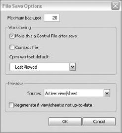
Save the file as a central file. To do so, go to the Application Menu and choose Save As, choose Project. In the Save as dialog box click Options. In the resulting dialog box (Figure 13.31), select the Make This a Central File after Save check box and finish by clicking OK.
Make local copies of the central file. You do this by saving the same file from your server where it's located onto the local machines of the other users.
Draw the basic layout of the building, exterior shell, and so on.
Start creating worksets and naming them accordingly.
Move elements into appropriate worksets (select elements, open the element properties, and in the Instance Properties dialog box under Worksets, change the workset to which the elements need to belong).
Working in the central file means that you will go against everything any IT manager ever yelled at you for. Remember: No one ever works in the central file. Everyone works in their local files (which are local copies of the central file) and works directly off their C drives. This approach to worksharing has a couple of advantages:
It allows more than one user to make changes to the file.
It's more responsive as the file gets larger, because the access speed to your hard drive is faster than it is to most networks.
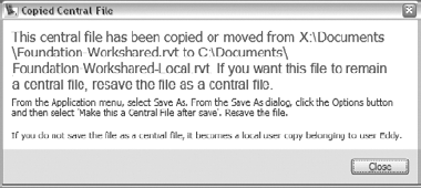
You can make a local copy by dragging and dropping the central file to your desktop or anywhere on your C drive. Open that file. You'll originally see the message shown in Figure 13.32, alerting you that you have a local copy of a central file. Revit maintains the link between your local copy and the central file provided you don't move the central file from its location on your network.

Once you're in a worksharing environment, every element added to the file belongs to some workset. Try to keep model elements in a workset other than shared levels and grids, because these worksets may be locked down at some point to avoid accidental movement of key datums. To make sure you're placing elements in the proper workset, check the Worksets panel (see Figure 13.33). The workset shown in this box is the workset your elements will be drawn on.
A helpful toggle in the Worksets panel is the Gray Inactive Worksets button
Note
Create a filter that applies a graphic override based on the active workset. Now you can quickly identify which elements are on which workset.
There are two ways to save your work when you're using a workshared file:
- Save
The Save tool only saves the work you've done on your local copy; the work isn't shared. This is useful when you're in the design phase and trying different designs, and you aren't ready to share your work with others.

- Save to Central
Next to the Save tool is the Synchronize with Central button. Use it to commit your work to the central file. When you do so, your work appears in the central file and becomes available to the entire team. Saving to central also acquires the changes that others have made and loads them into your model.
