We've reviewed how to create building elements, generate views, and get these views onto sheets. We also covered how to export the information you create in Revit so that it can be used by other downstream applications.
In this chapter, we'll review paper printing as well as some lightweight digital outputs (PDF and DWF). We'll also look at how to take advantage of Autodesk Design Review in conjunction with Revit as a way to exchange digital markups. We will then offer some best-practice tips on printing. Topics we'll cover include:
Printing your documents
Revit printing tips
Export your BIM data
In this section, we'll discuss a few of the specific settings and commands you'll use to print from Revit. If you've been working in the Windows environment, you'll find that printing from Revit is straightforward, because it's very similar to other Windows-based applications.
Selecting Application → Print brings you to the dialog box shown in Figure 12.1. All the features for printing are found here.

Printing to a file allows you to create a printing or plot file (.prn or .plt) that can then be sent to a printer independently of the software in which it was created. Creating a .plt or .prn file means you can print many copies of the drawing set, at any time, without having to interrupt your workflow while you print. To print to file, select the Print to File check box below the Properties button.
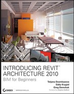
Selecting the "Create separate files. View/sheet names will be appended to the specified name" option creates a separate file for each view or sheet in the selection (Figure 12.2). This option is sometimes more practical for printing large sets. If paper runs out in your printer or any other interruption happens during the printing process, you can continue printing the remainder of the sheets later. By contrast, if you're printing from a single file, you'll need to start the print job over.
In this section of the Print dialog box, you can define exactly what you want to print. It includes these options:
- Current Window
This option prints the full extent of the open view, regardless of what extents of that view are visible currently on your screen. For example, if Figure 12.3 is what you see in Revit, Figure 12.4 will be the output when Current Window is selected.
- Visible Portion of Current Window
This option prints only what you see in the frame of the open window framed for the sheet size you've selected. Figure 12.5 shows a Revit screen (what you see), and Figure 12.6 shows what will print if you select Visible Portion of Current Window.
- Selected Views/Sheets
This option allows you to define a reusable list of views, sheets, or any combinations of views and sheets. This way, you can essentially batch-print a job by sending large quantities of sheets to the printer in one shot. You can also save these selections for later print jobs. Figure 12.7 shows the View/Sheet Set dialog box.


Note
Another way to print what you see on your screen is to use the Prt Scrn key, typically found at the upper right of a Windows keyboard. Pressing this key copies a full image of the screen to the clipboard. From there, you can paste it into Photoshop or another image application. If you want to print only the active window and not your entire desktop (an example would be a dialog box or just the Revit window), use Alt+Prt Scrn. If you have a dual-monitor configuration, use this technique to limit your print screen to the active application frame.
This dialog box lets you pick any view or sheet to include in the View/Sheet Set. If you only want to include sheets in a set, use the Show options at the bottom of the dialog box to shorten the visible list. This will allow you to select only sheets or only views if you so choose.
This is a great tool to help define print lists. Some examples of what you might want to use these selections for would be a 100 percent construction document package or a specific set of presentation sheets.
Note
The Show check boxes only control what you see in the sheet/view list. They don't control what will or won't be printed. In fact, if you have selected something from one of the two categories and then turn off the visibility of those items (e.g., if you select a sheet, then uncheck Sheets), those selected elements will still print.
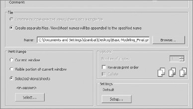
The printing environment is set up using the Print Setup dialog box (Figure 12.8). This gives you options for selecting a printer and settings for printing. You can save these settings with a name so that they can be reused in later sessions of Revit. These settings can also be transferred to other Revit projects if need be, using the Transfer Project Standards tool located on the Manage tab on the Project Settings panel. Let's take a look at some of the printing options available to you.
Note
To transfer print settings from one project to another, open both in the same session of Revit, and choose the manage tab on the project settings panel.

Hidden Lines Views
Views in Revit can be displayed in four graphic modes: wireframe, hidden-line, shaded, and shaded with edges. The most commonly used type of view is hidden-line. You'll choose this type for floor plans, sections, and elevations, and sometimes even for 3D.
Revit lets you select whether you wish to print this type of view with vector processing or raster processing of the hidden lines. Vector is faster; however, you need to be aware of some nuances when working with hidden-line views. For example, transparent glass material prints transparent with raster processing but opaque with vector processing.
Figure 12.9 shows a perspective in hidden-line mode printed using raster processing. Figure 12.10 shows the same perspective printed with vector processing. Note that you can't see through the glass using this setting.


The Options pane is at the lower left in the Print Setup dialog box. It includes these options:
- View Links in Blue
View links are hyperlinked tags that lead you from one view to another or from a sheet to a view. They appear blue in Revit and print black by default, but you can specify to print them in blue, which is how they appear on the screen.
- Hide Ref/Work Planes; Hide Scope Boxes; Hide Crop Boundaries
These three check boxes let you decide whether to print various Revit-specific graphics, including reference planes, scope boxes, and crop boundaries. Using these options allows you to maintain the visibility of crop boundaries during documentation and then hide them en masse when printing. This is a significant time-saver as compared to manually turning off crop boundaries.
- Hide Unreferenced View Tags
During the course of a project, you may create a lot of elevation tags, section flags, or detail callouts for working purposes that you don't wish to be printed in the final documents or placed on any sheet. These view tags are referred to as unreferenced, and Revit gives you the option to not print them.
In Figure 12.11, note the section lines, callout views, and crop region in the floor plan.
Figure 12.12 shows that when you select Hide Crop Boundaries and Hide Unreferenced View Tags, some features from the view don't appear on the print. These will not show up in the Print Preview either.


Here are some helpful, specific hints about printing from Revit. These tips will help you to optimize your print performance whether you are printing to a paper or digital format:
When you're plotting large-format sheet sizes to plotters such as the HP DesignJet or OCE printer, change the plotter's settings so the data is processed in the computer. (This is probably handled through the printer's Advanced Settings menu. Each printer has its own command sequence.)
Be sure the Far Clip Plane is active for the view and set to a reasonable distance. (Choose the Far Clip Plane option in the View Properties dialog box for each view.) Having a distant clip plane can significantly slow your printing process.
Hatches and other types of fill patterns, when used extensively or in high density, can affect performance. (The Sand fill pattern is an example.) If possible, turn them off, or exchange them for less performance-intensive patterns.
Level of detail can affect performance. If you don't need to print in Fine view, reduce it to Medium or Coarse.
A DWG, when mistakenly inserted in all views, can affect printing speed. If you notice that your elevation or section prints slowly, the reason may be a DWG that is imported into that view but shows as a single line and thus is unnoticeable because it is oriented to plan views. This will happen if you insert a DWG in a plan view, but are printing an elevation or section view. You can check which DWGs are showing by opening the Visibility/Graphics dialog box, clicking the Imported Categories tab, and deselecting the Show Imported Categories in the This View check box.
For general performance improvements, including when you're printing, Revit has a 3GB switch functionality. You can learn about it by navigating to the Knowledge Base area of the Autodesk website. Go to
www.autodesk.com/support, and choose Revit Architecture. The 3GB switch and Revit document is linked on the resulting page. If you are using Windows Vista or Windows XP 64 bit, you can use the 64-bit aspects of the OS to utilize more RAM by loading the 64-bit version of Revit 2010.Offices have a finite number of printers. Set up each of your plotters and printers in your Revit template. That way, you don't have to re-create them for each new project.
Set up some standard sheet sizes: 11″×17″, 81/2″×11″, Size E1, and Full Size E1 are some standard architectural sheets. Add these to your template as well.
Keep in mind that some printers are not capable of printing graduated shades of gray — instead, they rely on printing dots (like newsprint). The results can be undesirable for views that need to show solid fills of varying shades of gray (for example, when shadows are visible).
The construction process goes through many iterations and exchanges of information among different parties. Exchanging a full-blown, data-rich building information model is not always required, and not everyone on the project team will be using Revit. Many team members just need to see a drawing to approve or mark up some changes and send it back to you. Some team members may be using older computers that can't handle large files effectively (or at all). You may also not be ready to share your intellectual property with the world in the form of editable drawings. Finally, you may be concerned about unauthorized appropriation or editing of your documents by others. This is where using lightweight digital output comes into play.
You need to be able to share drawings and documentation in a safe, noneditable, lightweight form that can be viewed by others outside the world of Revit. This is the problem that some new publishing technologies are trying to solve.

Design Web Format (DWF) is Autodesk's solution for publishing intelligent data in a light, easy, and secure way while preserving the power of the information embedded in the design documents. DWF files are highly compressed, and are capable of transmitting big design models via e-mail or other limited-transfer technologies.
Choose Application → Export → DWF (Figure 12.13).
You can export a Revit project as a DWF file and send it to various stakeholders in the building process. With the latest version of Autodesk Design Review (we will discuss Design Review in more detail later in this chapter), it is possible to view and even mark up these files. Microsoft Vista also has an embedded DWF viewer, so the receiver won't have to install a separate DWF viewer, as required with machines running Windows XP or earlier.
DWF EXPORT OPTIONS
Revit is a BIM modeler with tons of information embedded in it about each element within the model. Much of this information is also published into the DWF format. You additionally have the option to send model and room data with the DWF. The DWF Export settings are available by choosing Application → Export → DWF and selecting the DWF Properties tab (Figure 12.14).

When you select the Element Properties option under Export Object data on the DWF Properties tab, all the property information about the model elements in the view that is being exported is published to DWF. This allows anyone viewing the DWF to select an object in that view and see its properties. Some examples of these properties are area, length, family name, and so on.
Selecting the Rooms and Areas check box publishes additional information that isn't included in Model Elements, because in Revit, rooms and areas are objects rather than physical elements. Room area and perimeter are two examples of these physical element properties. This information can be helpful, especially to facility managers to whom you may be sending your DWFs.
EXPORTING A VIEW OR SHEET AS A SINGLE FILE
When exporting to DWF, you can make separate DWF files for each view or export all views into a single DWF file. To do this, select the Export Each View or Sheet As a Single File check box in the Export dialog box. Note that even though DWF is a lightweight format, depending on the size and complexity of the project you're dealing with or the number of sheets (or views) you want to export, a DWF can be large; you may want to consider splitting it into a few separate DWFs.
When you export to 2D DWF, the information is exported in 2D flat drawings, regardless of the view type. This means that perspective and axonometric views are exported as flat images. Figure 12.15 shows a 2D DWF. Note that although the drawing is technically in two dimensions, it retains its visibility settings and element properties.

Exporting a 3D DWF creates a full-blown 3D DWF model. When it is opened with a DWF viewer, you can spin the model around, turn visibility of separate elements on and off, slice the model in sections, make elements transparent, and review the model in a variety of ways. Figure 12.16 shows some of this functionality.

The cross-section tool lets you slice the model in any direction and reveal the exterior. You not only see the 3D information and can easily move around and review parts of the building, but you can inspect the properties of any element available in the model.
Sharing digital models using 3D DWF has proven to be of special value for construction companies. It both facilitates design visualization in the field and allows builders to do a constructability review in the office before problems arise in the field. Also, 3D DWFs are useful to owners because they effectively convey the future look and feel of their building.
Autodesk Design Review is a free application created by Autodesk that allows you to review, mark up, and track changes to 2D and 3D designs. These comments are stored in the DWF file, and even show up in your Revit file by linking in a DWF file. Design Review is installed automatically when you install Revit, but can also be downloaded separately from Autodesk's website. (www.autodesk.com/designreview). This is a very lightweight application that can be easily downloaded, installed, and used by all the stakeholders on the project team.
In the Design Review application, when you select a Revit element, such as a wall in the 3D view (Figure 12.17), it displays all its properties in the left pane. Viewing models and querying element properties is just one advantage of this tool. The DWF environment opens up new, intelligent ways to share information, propose revisions, and discuss document changes to the BIM model.

In a time-honored scenario, an architect prints and sends a set of physical drawings to the engineer. The engineer reviews them, physically marks with a red pen the necessary changes, and sends the drawings back to the architect. The architect reviews the revised drawings and re-creates the changes in the digital files. This process is repeated throughout the life of the project. Not only is there a lot of room for error with all the transposing of information, but a lot of money is spent on printer paper, postage, and shipping. The transmission of black-and-white, smeared facsimiles or poor penmanship can result in misinterpreted information. Using DWF reduces costly errors and omissions in your communications with team members and clients. Let's review how you can leverage these tools.
A WORKFLOW SCENARIO: MARKING UP A 2D DWF FROM A REVIT MODEL
In Revit, the architect opens the sheet they wish to send to a consultant, then exports it to 2D DWF and sends it via e-mail.

The consultant opens the DWF in Design Review, reviews the drawings, makes a markup with desired changes directly in the digital file, and sends the DWF back to the architect (e-mail again). Figure 12.18 shows a sample marked-up DWF.
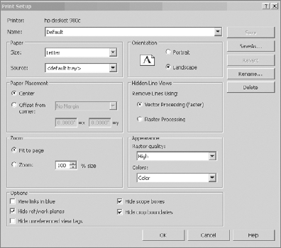
The architect links the DWF markup (choose the Insert tab and from the Link panel select DWF Markup) into the Revit file from which the DWF was originally generated. The red markup shows up on the correct sheet and in the correct position, as shown in Figure 12.19.
Note
Markup functionality only works with Revit sheets. Make sure you are publishing sheets, not views, when working with the DWF markup features.
Each linked markup has a defined status (None, Question, For Review, or Done), which is shown in the Element Properties dialog box for each markup (Figure 12.20). When initially linked, the default status is None, but it can be changed to another status after an initial review. Thus, the architects in the team can track whether a certain change request has been executed or is still under review or discussion.

Design Review lets you mark up and add comments not only to 2D DWF files but also to 3D DWF files. The process is the same: you select the Markup tool from the toolbar, click the spot that you want to comment on, and type in the text box that opens (see Figure 12.21). The marked-up 3D DWF, however, cannot be linked back into the model.
Collaborating through a digital publishing mechanism is of value for many participants in the building industry because it allows for shorter review cycles; faster decisions; better communication of information; better visualization of projects; and better tracking, archiving, and documenting of change orders.

Portable Document Format (PDF) is an Adobe-created document format. The main uses of PDF in the past were securing documents the originator didn't wish to have edited and putting content into a manageable file size for digital transfer. Today, PDF is also commonly used to transfer drawings among team members and reprographic companies. (A reprographic company can create large-format copies, which does pages at 30″×42″ (Arch E1) or other large-format sheet sizes.)
Revit supports printing to PDF through the use of printer drivers. You need at least one PDF driver installed on your machine to be able to create PDFs. If you do not own a copy of Adobe Acrobat (Adobe's PDF creator), there are other solutions currently on the market that also make PDFs. Pdf995 (www.pdf995.com) is an inexpensive solution that can be installed on any workstation. For server-based solutions allowing multiple people to print via PDF to a networked printer, Jaws PDF is also available (www.jawspdf.com).
Another printing format to consider adding is EPS. This offers fantastic vector resolution and is great if you need to open for further postproduction in Photoshop or Adobe Acrobat. More information can be found at:
www.adobe.com/support/downloads/product.jsp?product=pdrv&platform=win |
Or check out the Autodesk User Group International (AUGI) post at:
http.//forums.augi.com/showthread.php?t=36877&highlight=eps