No set of documents is complete without annotations that add textual or numeric descriptions to the drawings. The need to add dimensions, tags, and textnotes to aid in the communicating design intent is still very much a part of the BIM workflow, and Revit is designed to support that workflow with some very intelligent, bidirectional annotation tools.
Topics we'll cover include:
Annotating your project
Tags
Dimensions
Text and keynotes
In any set of documents, showing geometry alone isn't sufficient to communicate all the information a builder or fabricator needs to construct the building. Tags, keynotes, text, and dimensions all need to be added to the drawing in order to clearly and concisely guide construction. They assist you in taking your model data and clearly documenting it for others to read and understand.
Starting where you left off, with some views placed on sheets, you'll continue to build your set of drawings by adding annotations to the views.
Note
In Revit, annotations, dimensions, and tags are placed in the views themselves, not on the sheet. This might be different from the way you are used to working in AutoCAD, so remember this well. This allows you to annotate a view at any point in the process, before or after views have been placed on a sheet.
The exception to this occurs when you're annotating a perspective view. These views don't allow for text, so you'll need to place the text outside of the view after it has been placed on a sheet.
Tags are textual labels for architectural elements such as doors, walls, windows, rooms, and many other objects that architects typically need to reference in a set of drawings. In Revit, tags are intelligent bidirectional symbols that report information stored in the properties of an element. A value can be directly edited from the tag; likewise, editing an element's properties affects the tag. For example, selecting a wall tag (Figure 10.1) returns the wall type that is set in the properties of the wall itself. This is a simple, standard-looking wall tag. The tag, however, can display richer information, such as the wall's fire rating or manufacturer, or any other value of the wall's properties. You can design it to suit any graphical and informational requirements that you have.

Revit comes with a variety of predefined generic tags. All of these can be customized to meet your office's graphic requirements. The set of tags preloaded into the default template covers many common requirements but is by no means exhaustive. Many firms have created their own tags and added them to their project templates so they are available during project development.
Most categories of elements in Revit can be tagged, and you can load multiple types of tags for each category. Tags are loaded from the Loaded Tags dialog box, which you access by expanding the Tag panel options on the Annotate tab. The resulting dialog box lists all the Revit categories that can be tagged. Click the Load button to load new tags into your project.
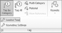
You can insert tags and load additional tags from the Tag panel on the Annotate tab (see Figure 10.2).
The Tag button will put you into a tag placement mode, but you can also access the loaded tags dialog box by clicking the Tags button on the Options bar. The tag button will only be available in certain types of views (the Tag button is deactivated in 3D views, schedule views, etc.). If you click this button but don't have a tag loaded, you'll be prompted to load a tag. During tag placement, the Options bar lets you position a tag in several ways. Figure 10.3 shows how the Options bar appears.
Tags can have a horizontal or vertical orientation and may or may not have a leader line. In the case of a wall tag, you typically have a leader coming from the wall, whereas you don't typically use a leader with a door or window tag.
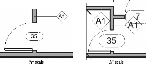
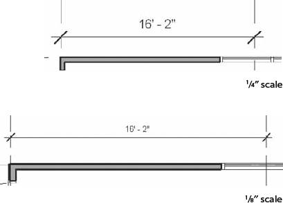
Tags will also dynamically adjust to the scale of the drawing. If the text of a tag is set to read at ⅛" (3 mm), it appears in the view at such a size to always print in that absolute size regardless of the scale (see Figure 10.4). This means that once a tag is placed in a view, the view can be resized and the tags will remain the same printing size. Depending on the scale of the drawing, you might need to adjust the position or location of the tags for better visibility, but once a tag is inserted, you will never have to reinsert a tag simply to change scale.
Note
You can add tags to your project after the design phase or during the actual creation of the elements. It really depends on the workflow you follow. A majority of firms first design and then document and annotate later in the process. At the same time, some practices tend to annotate during the design phase. In this case, for some elements such as doors and windows, you have the option to tag during placement, which will annotate your drawings right from the start. Keep in mind that using the Tag All Not Tagged option allows you to achieve rapid tagging of elements in a view in the event that you decide to tag elements long after the design process ends.


- Tag By Category
This option allows you to tag elements in the model by category or type. Examples are doors, walls, windows, and other commonly tagged elements. After you choose By Category, the elements you can tag are highlighted as you mouse over them in your view. Revit also displays a ghosted preview image of the tag you're inserting and the value in that tag, as shown in Figure 10.5.
- Multi-Category
Use the Multi-Category tag when you want to tag an element across different family types — for instance, when you're using a similar glazing type in your windows and exterior doors and you want to be able to tag the glazing consistently. The Multi-Category tag allows you to have the same tag and tag value for the glazing in both families. (Fire rating is another common application of this tag.)
- Material
The Material tag lets you tag the materials in a given family. For example, tagging a wall by material exposes materials used in the wall construction such as gypsum board or metal studs. This allows you to tag these elements separately.
There are two ways to modify the value text in a tag. Selecting the tag makes the value text an active control and turns the text blue; just click the blue text and begin typing. You are not only changing the value displayed in the tag but also changing the type property of that element (the Type Mark parameter). The second option is to open the properties of the element being tagged. Using a wall example again, if you select the wall, open its type properties, and change the Type Mark field to a new value, the wall tag updates instantly and reflects this change. See Figure 10.6 for examples of each location.
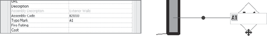
Whichever way you choose, it is important to know that you will be changing the symbol text for every instance of that element type and thus of its tags. Therefore, if you change the wall type mark from A1 to A2, it will change every instance of that wall that was previously tagged A1 and all wall tags will thus display A2. If 10 walls were tagged A1, all 10 are now A2.

Only if you use the first method to modify text — changing it directly in the tag — are you notified that you're making a global change (see Figure 10.7). If you choose to change the value in the Type Properties dialog box, Revit assumes you understand this will change that property for each of the elements of this type in the model.
Some tags only report instance values — values that are unique to the individual element. A room tag or door tag is a common example. In that case, changing the property of the room or the tag will have an effect only on that one room. The room tag graphics are consistent, but the room name varies from room to room. Doors are often tagged like this, with a unique numeric value for each door. With these types of tags, Revit will detect if you enter duplicate values and warn you when that happens.
Instead of manually tagging each and every element one by one, in Revit you can tag many elements at once using the Tag All tool on the Tag panel of the Annotate tab. This timesaving feature lets you tag all the elements in a view with a single click. During early phases of design, you often aren't concerned with tags and annotations but are more focused on the model. Tags can become graphic clutter that obscures the design at times.
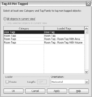
Later in the process, when you're happy with the design, you may want to annotate the drawing quickly. This is where the Tag All tool is helpful. When you select this tool, the dialog box shown in Figure 10.8 opens. You can orient your tag or add a leader to it before tagging all the listed elements in your current view.
If you have some elements selected, you can choose to tag only those selected elements.
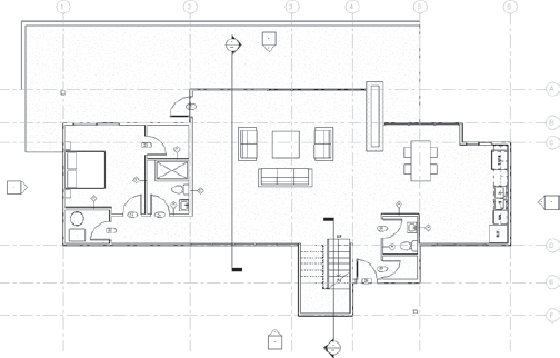
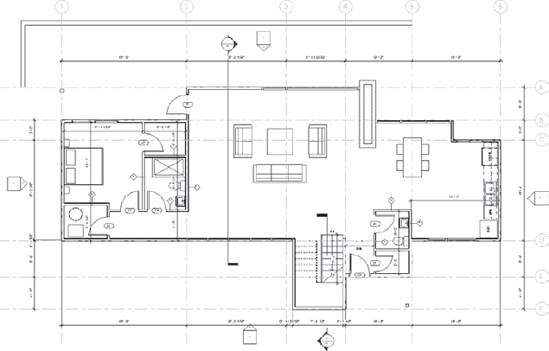
In the Source_House_Beginning_Detailing.rvt file at the book's companion web page, www.wiley.com/go/introducingrevit2010, open the view called First Floor Plan. In this view, using the tools mentioned, let's add tags for the doors and walls:
Move your cursor over a door, and click when it highlights. Make sure your leaders are turned off on the Options bar for door tags.
Highlight and select the interior walls. For wall tags, use the Options bar to turn on leaders and adjust the leader length from ½" to ¼". The finished floor plan looks like Figure 10.9.
Note
If you have forgotten to activate leaders when creating the tags, don't despair — you can always add them by selecting the tags, individually or with multiselect, and checking the Leader check box in the contextual tab for tags. The same applies if you decide you don't want tags to have leaders.
Dimensions are used to convey the distance or angle between elements or parts of elements. In Revit, a dimension is a bidirectional annotation that essentially tags distance or size. The word bidirectional means that you can edit the distance directly when elements are drawn or selected; likewise, the dimension updates automatically as the distance between elements changes (Figure 10.10). Dimensions are annotations, making them view-specific elements that appear only in the view where they're drawn. If you need to repeat the same dimensions from view to view, you can copy and paste dimensions; they will locate the same model elements. Use the paste-aligned method described in Chapter 5, "Modifying Elements."
The parametric nature of dimensions in Revit means that dimensions can't be overridden or cheated numerically as they can be in CAD. This preserves the integrity of the model and the design. If you hear that Revit "won't let you cheat," it's true. And trust us, this is for your own good! Dimensions in Revit report the actual value of the distance they span. If the distance is 4′-0″ (120 cm), the dimension reads 4′-0″ (120 cm). You can't change the numeric value of a dimension without changing the model. For example, if the distance between two elements is supposed to be 3′-6" (106 cm), you would need to modify the distance between the two elements to get the dimension to report your intent.
Like all annotations in Revit, dimensions adjust to the scale of the drawing. They will always appear at the proper scale in the view. If you change the view scale, the dimensions automatically resize. In Figure 10.10, the first image shows the dimensions at ¼″ (1:50) scale, and the second image shows the same dimension string after the scale was changed to ⅛″ (1:100) in the View Control bar.

By default, a linear string of dimensions only dimensions parallel entities. Nonparallel elements by their very nature have a dynamic dimensional relationship. The dimension between nonparallel elements will vary based on where the dimension falls between them. Because of this, Revit defaults to only allowing parallel objects to be dimensioned. Dimensions in Revit always read from the bottom or the right. This follows standard architectural sheet layout conventions. We mentioned that you cannot override the numeric value of a dimension, but this is not to say you cannot override the value with text. You have the ability to add text to multiple parts of the dimension string, including replacing the value with text. Figure 10.11 shows some examples of dimensions with text integrated.
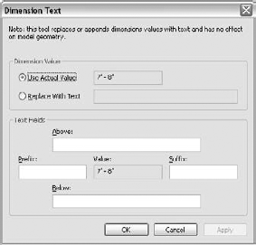
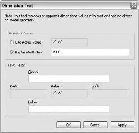
To add text to a dimension string, select the dimension, then click on the blue dimension text. A dialog box will open allowing you to add text above, below, as a prefix, or as a suffix, or even replace the value with text (Figure 10.12).
By default, the dimension string will use the actual numeric value, shown in the upper portion of the dialog box. You can then add text by typing into the various text fields to add above or below or as a prefix or suffix.
To replace the value with text, choose the Replace with Text option. This will disable the prefix and suffix fields and allow you to type any text you want. Figure 10.13 shows the dialog box, with the text V.I.F typed in.
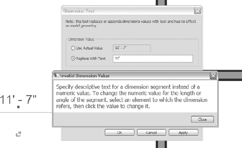
If you try to add a number in this text field and click OK, you'll get a warning and will not be allowed to make that kind of edit. Figure 10.14 shows the result when trying to replace 7′-8″ with 8′.
To create dimensions, select the desired dimension tool, and begin picking elements in the model to dimension. For linear dimensions, parallel edges (references) of elements will highlight as the mouse moves over them, indicating a valid dimension candidate. After two references are selected, a preview graphic of the dimension line appears and moves with the mouse. When you've finished selecting references, move the dimension string to the desired location, and click empty screen space to finish the string.
Note
When you add dimensions in Revit, use the Tab key to cycle through the selection options.
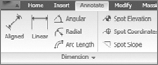
Once a dimension tool is activated, the Place Dimensions tab appears, and you'll be able to change the type of dimension here if you need to (see Figure 10.15). Here are the buttons in the order in which they're listed (from left to right) on the Options bar:

- Linear
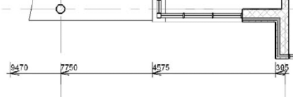
Linear dimensions are parallel to the sheet edges. In the case of your angled wall, the dimension is parallel to the bottom of the sheet, as shown in the bottom dimension of Figure 10.16.

- Angular
Angular dimensions show the angle between two elements.

- Radial
Radial dimensions are used to dimension to the radius of an arc or circle.

- Arc Length
Arc length dimensions show the length of an arc.

The other choices on the Options bar allow you to choose your preferred pick points:
- Prefer
This gives you the option to choose what references in walls you want the dimension to prefer during placement. You can change what a dimension prefers during placement by using the Tab key to cycle through nearby references. The options shown in Figure 10.17 are Wall Centerlines, Wall Faces, Center of Core, and Face of Core.
- Pick
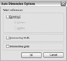
This gives you the option to either choose individual references in sequence using the Individual References option or use the Entire Wall option, in which case you click walls and Revit automatically finds the ends of the walls and puts a dimension there. The Entire Wall selection has additional options — click the Options button on the Options bar — that can be further refined so door and window openings or even intersecting walls and gridlines can be automatically generated. The Auto Dimension options are shown in Figure 10.18.

To dimension non-coplanar entities, such as two walls, select the first element. Then, before selecting the second element, use the Tab key to cycle through the selection options until you highlight a point, as shown in the enlarged doorjamb in Figure 10.19.
The finished dimension appears in Figure 10.20.

There are some additional type parameters for linear and aligned dimensions that will allow you to create baseline and ordinate dimension string formats. These tend to be used by structural engineers and construction firms, but we'll explain the behavior for you.
Baseline dimensions are multiple dimensions measured from the same baseline (see Figure 10.21). Some construction firms practice this type of dimensioning, especially when nonorthogonal references need to be documented for clearer construction.
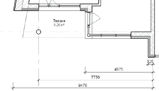
Here's how baseline dimensions work: The first selected point or element will be the baseline for the dimension. The second reference selected will determine the direction of the dimension string, and the following selections will add more dimensions. Note that the baseline dimension string is a single element; delete it and all of the dimensions in the string will be removed.
Note
If during placement of the dimension string at some point you select a reference on the opposite side of the baseline reference, that new reference will become the new baseline reference, the dimension string will restack, and all strings will reference that new baseline reference.
You will find examples of baseline dimensions in the default template delivered with Revit 2010, but you will most probably have your own office template and will need to create your own types. To create your own baseline dimension type, follow these steps:
Select any of your existing linear dimension types, click on the Element Properties, and in the Instance Properties dialog box, click Edit Type.
Duplicate the type and give it a unique name (we suggest using the word baseline in the name).
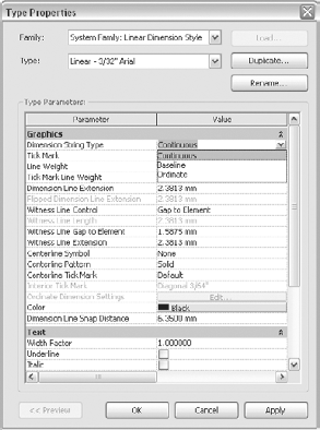
Select the Dimension String Type property and change it from Continuous to Baseline (Figure 10.22).
You will notice that once a baseline dimension is created, a flip control symbol shows up: this control is located at the origin witness line and lets you flip the dimension baseline from end to end (Figure 10.23). You can access the same behavior by right-clicking and selecting Flip Dimension Direction from the context menu.

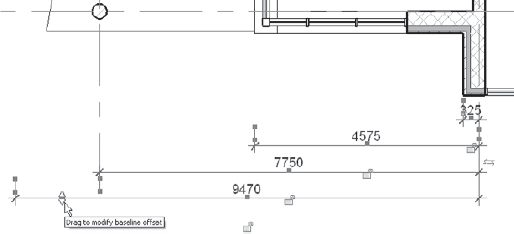
Also notice that when selecting a baseline dimension a drag control appears on the screen (Figure 10.24) — this will let you drag the entire set of dimensions to modify the baseline offset and thus adjust the position of the baseline dimension.
You can change a baseline dimension back to linear dimension using the Type Selector when a dimension is selected. Doing so will collapse all of the dimension strings back into one string.
Ordinate dimensions measure the perpendicular distance from an origin point called the datum to a dimensioned element. These types of dimensions are more typically used by mechanical and structural engineers. Using the same example as in Figure 10.24, Figure 10.25 shows how that same dimension looks when converted to an ordinate dimension type.
Creating your ordinate dimension type is the same as creating the baseline type, as previously explained. The difference is that you will select Ordinate as the Dimension String Type setting when creating the new dimension type.
Revit dimensions will recognize the intersection points of reference planes, grids, levels, walls, and lines. This allows for much more effective dimensioning. An intersection between these elements is recognized and can be dimensioned to or from. When you dimension to an intersection, a green dot will appear, indicating the crossing point as a reference. When dimensioning from an intersection point, you'll need to use the Tab key to get to the intersection point.

By selecting a dimension and opening its properties, you uncover a host of options, as shown in Figure 10.26. You can also access this dialog box by clicking on the arrow to access the expanded panel for Dimensions. Here you can get to the type properties of the various dimension styles.
First, we'll discuss the parameters for which you can set values. These are listed in the upper pane of the dialog box.
- Dimension String Type
This allows you to change dimensions from continuous, baseline, or ordinate dimensions, as we just covered.
- Tick Mark
This option allows you to select the style and size of the tick marks in Revit. The tick mark is the angled line crossing the intersection of the witness and dimension lines (shown in Figure 10.27).
- Tick Mark Line Weight
This option controls the line thickness for the tick mark only.
- Dimension Line Extension
This option controls the length of the extension to the dimension line after the tick mark (shown in Figure 10.28). The dimension line is the line the dimension text sits on or over.
- Flipped Dimension Line Extension
This option is available only if Tick Mark is set to Arrow. It controls the extent of the dimension line beyond the flipped arrow if the arrow flips on the ends of the dimension string.
- Witness Line Control
A witness line is the line parallel to the elements dimensioned and perpendicular to the dimension line. This option toggles the setting to show or not show the second witness line. To have both witness lines show, use the Gap to Element setting.
- Witness Line Length
This field becomes active only if the Witness Line Control is set to Fixed Dimension Line. You can set the length of all the witness lines in the dimensions.
- Witness Line Gap to Element
This option controls the distance between the witness line and the element dimensioned.
- Witness Line Extension
This option controls the length of the witness line after a tick mark.
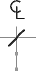
- Centerline Symbol
This option shows a symbol if you've dimensioned to the centerline of an element (see Figure 10.29).
- Centerline Pattern
This field changes the line style of a centerline.
- Center Tick Mark
This field by default is blank. It allows you to add a tick mark on the inside of the witness lines.
- Interior Tick Mark
This option is available only when Tick Mark is set to Arrow. It designates the tick-mark display for inner witness lines when adjacent segments of a dimension line are too small for arrows to fit.
- Color
- Dimension Line Snap Distance
This option aids in the use of stacked dimension strings.


Next, let's look at the options in the Text pane, which occupies the lower half of the Type Properties dialog box:
- Text Style Options
You can make the text bold, italic, or underlined.
- Text Size
This field changes the size of the dimension text.
- Text Offset
This option changes the distance the text is placed from the dimension line.
- Read Convention
This option shows you the default values of the dimension text position. In Up, then Left (the default value), the dimension text reads from the bottom of the sheet and then from the right of the sheet, appearing above the dimension string depending on whether it's horizontal or vertical.
- Text Font
This field controls the font of the dimension string. It's possible in Revit to have a font for dimensions that's separate from notes or other text.
- Text Background
The options for this value are Opaque and Transparent. It changes the appearance of the box surrounding the text.
- Units Format
This option controls the dimension string tolerance and unit displays.
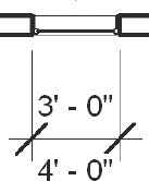
- Show Opening Height
This option returns the height of an opening below the dimension string. In the dimensioned window shown in Figure 10.30, the width is shown as 3′-0″ and the height as 4′-0″.
Note that while the position of the dimension text is defined in the properties of the dimension type, you can still manually change the position to avoid a clash of information and move the text to a more appropriate place in the project. To do that, use the blue dot displayed right below the dimension text when a dimension chain is selected, and move it around. Notice that when you do that, any text added to the dimension text as well as all prefixes, suffixes, the text above, and the text below will also move, as they behave like one group of elements. Figure 10.31 shows a dimension value moved away from the string. Notice that the automatic leader and all dimension text values are preserved.

Now that we have covered the basics of dimensioning, let's try it on the first floor plan view you've been working on in the Source_House_End_Detailing.rvt file. Using the default dimension settings and the linear dimension style, you'll add dimension strings to the walls in the floor plan.
For interior walls, choose the Dimension tool. On the Options bar, select Wall Faces from the Prefer menu.

For the gridlines, choose the Entire Walls option from the Pick drop-down menu. Before placing the dimensions, click the Options button, and then select Intersecting Gridlines. Pick parallel walls that are perpendicular to the grids, and you'll see the ease with which a string of dimensions can be generated (Figure 10.32).
The finished floor plan should look similar to Figure 10.33.
Notes are a critical part of communicating design and construction intent to contractors, subs, and owners. No drawing set would be complete without textual definitions and instructions on how to assemble the building. Revit has two primary ways of adding this information to the sheets: text and keynotes. Text in Revit consists of words arranged in paragraphs with or without a leader. Text can be used for specialized annotations, sheet notes, legends, and similar applications. Keynotes, the other tool for annotating a drawing, are element specific and can be scheduled and standardized in the Revit database. We'll explore the use and function of both tools in this section.
Text is easy to add to your view. You can access the Text tool from the Text panel on the Annotate tab.
Text can be added to any view, including a 3D view. To begin adding text, click the Text button after you've opened the view of your choice, select where in the view you wish to place text, and begin typing. To edit text you've already placed, click the text to highlight it, and then click it again to activate the text box. To move text once you've located it, select it and drag it, or use the Move command that appears in the Modify Textnotes contextual tab.
When you use the Move command, you move both the text and the leader. When you move text by dragging the arrow icon, you move only the text box, leaving the leader anchored in its original position.
As with all the tools in Revit, there are ways to change the look and feel of your text during creation. Once you've selected the Text tool, the options change to give you some formatting choices. Figure 10.34 shows the options available with the Text command.
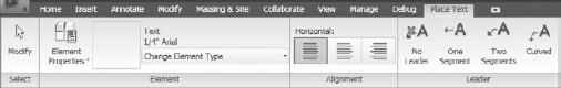
The Type Selector, available when selecting the Change Element Type button, allows you to choose a style for the text you're using. Each text style is managed through the familiar Properties dialog box, where you can modify parameters such as font and size. To create a new text style from an existing one, click the Element Properties button and choose Edit Type in the Instance Properties dialog box. From there, choose Duplicate, give the style a new name, and make your adjustments to the properties. This process is identical to adding a new type to any existing Revit family.
Justification options are displayed as icons, allowing for left-, center-, or right-justified text.
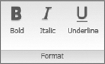
After selecting a textnote, click the blue letters to edit the text. When you're editing the text, you're given additional formatting in the edit text tab for bold, italic, and underline. These apply to whatever text you've selected in the note.
Most text parameters are located in the Type Properties dialog box for text. It's here that you define font, style, and size. Figure 10.35 shows the properties available for text.
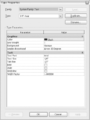
The following list discusses these properties and explains show you can modify those values to customize your text in your project:
- Color
This is where you can choose the font color.
- Line Weight
This option allows you to choose the line weight for the elements associated with this text type. This includes the line weights of any leaders or arrowheads. Note that line weight options for the leader are found under Object Styles.
- Background
This gives you the option to have a background for your text box that is either opaque or transparent. Opaque creates a white box (blotting out the model behind it, as shown in Figure 10.36). Transparent leaves the text box clear and lets you see the model data behind the text (Figure 10.37).
- Tab Size
This option sets the distance your cursor offsets when you use the Tab key in a text box.
- Bold, Italic, Underline
These options mirror the commands available on the Options bar, allowing you to bold, italicize, or underline your text.
- Width Factor
This value lets you control the width of your text. A value less than one reduces the width of the text by a factor, and a value greater than one makes the text wider.


After you've placed a text box in the drawing, you have the option to go back and change some of the parameters. When text is selected, check the contextual tab: you can add and remove leaders and change the text justification (see Figure 10.38).
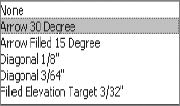
The leader buttons allow you to choose a leader style for your text before you add it to the view. From left to right in Figure 10.38, you can choose none, one segment, two segments, or an arc for a leader line. You can add any number of additional leaders to the left or right of the text box. The first two leader options are for leaders with lines, whereas the second two are for leaders with arcs. (You can't have a text box with both linear and arc leaders.) You also have the option to remove leaders you've added. Note that leaders will be removed in the opposite order in which they were added.
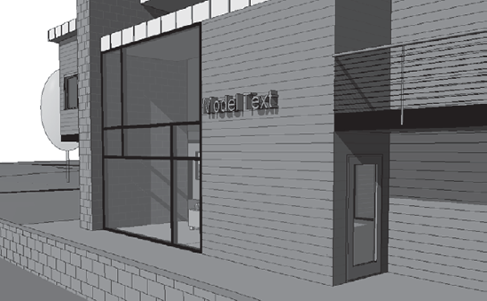
Model text is 3D text that appears as a model element in your project. The properties of model text are similar to the properties of other model elements, rather than those of text. Model text can have thickness, material, keynote, and other common model properties.
A classic use for model text is signage for a building entrance (Figure 10.39). Keep in mind that model text can also be created in the Family Editor, so that if the signage is repetitive, you can create a single signage family and use it several times in a project.
Model text height dimensions are given relative to the model. If you want the text to be 3′ tall in the model, it stays 3′ tall but becomes larger or smaller in the view depending on the view scale.
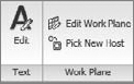
The Model Text command is located in the Model panel on the Home tab. To add model text to your drawing, click the Model Text button. You'll see a dialog box asking you for your text entry. Type your text, and click OK when you've finished. At this point, you're asked to place the text in the view you currently have active. If you're in a 3D view, Revit chooses a work plane based on the location of your cursor over model faces. Click to place the model text. After you've placed the text, you can select it and use the tools in the Modify Model Text contextual tab shown in Figure 10.40 to edit the text or reposition it.

- Edit Text
This button lets you change the text you typed. You can also edit the work plane on which the text was created.
- Edit Work Plane
This button opens another dialog box (Figure 10.41) where you can select a new work plane from an existing one or choose a plane of an existing Revit element.
- Rehost
This button allows you to move text from the element you've selected to another host element in the model. (We discussed this feature earlier, in the context of windows and doors.)

Keynotes and textnotes textual annotations that relate text strings in an external file to specific elements in the model. You can format font style, size, and justification in the same manner as for standard text, but keynotes and textnotes behave like a Revit family. This means you can insert different family types of text in Revit, just as you would door or window families. Changing one instance of the family type changes all the instances in the project. Because keynotes and textnotes act as families in Revit, they can also be scheduled. It is important to understand the difference between a keynote and a textnote.

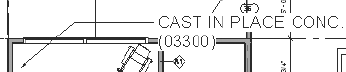
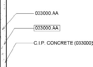
Keynotes are a way to annotate elements with references that refer back to another table of data. These are typically shown as a number followed by a letter. An example would be "03300.AA" and it might refer to a cast-in-place concrete wall. The "03300" portion of the note refers to the specification section the note is generated from, and the "AA" portion of the note is a sorting mechanism used to differentiate cast-in-place concrete from another note in Division 3 of MasterSpec. All of the notes on a given sheet are keyed back to a legend that is typically placed on the right side of a sheet. This reference is an aid to add more detail and understanding to the keynote without having to directly reference the specifications. Textnotes are similar to keynotes, but combine the text and the key into one note. This saves you from having to coordinate the legend on the sheet and puts the note right next to the item you are pointing to. See Figure 10.42 for examples of textnotes.
No matter which style you prefer, both the keynote and the textnote can be created with the same command in Revit. Since the Revit command is called Keynote, we will refer to the process from here on as keynoting regardless of the style of keynote (or textnote) you choose to use.
The Keynote command is located in the Tag panel on the Annotate tab. Adding keynotes in Revit gives you three options for keynoting an element:

- Element
Allows you to note an element in the model, such as a wall or a floor. This type of note is typically used if you want to note an entire assembly, such as a wall assembly. You can find this value in the family properties of that element.
- Material
Allows you to note a specific material in Revit. For example, this will let you annotate materials such as concrete, gypsum board, or acoustical tile.
- User
Allows you to select any model-based component in Revit and define a custom keynote for it. Notes defined this way differ from those defined under Element or Material because they're unique to the particular object selected. They can be used in conjunction with Element and Material notes.
A core concept of keynoting is how the notes react in the model. Keynotes are integrated into Revit just like any model element. Keynoting an object in Revit lets you associate a text value to that family's keynote parameter. This value is consistent for every identical element in the model. For example, all doors have a type parameter that lets you set the keynote value. If you keynote that door — anywhere in the model — the keynote will show that value. Likewise, if you ever change the value of the keynote for the door type, all keynotes will update automatically.
Keynotes are special in that you cannot edit the text of a keynote directly in Revit. All the keynotes in Revit are tied to an external text file, which is the only location they can be edited. This file can be modified at any point to add or remove values and notes. A sample portion of the Revit keynote file, RevitKeynotes_Imperial.txt, is shown here. This external .txt file is designed to keep annotations consistent by storing all of them in one repository. Every time you add or change the text of an annotation and reload the text file, it dynamically updates all the keynotes of that type used in the project.
03100 | Concrete Forms and Accessories | 03000 |
03200 | Concrete Reinforcement | 03000 |
03300 | Cast-in-Place Concrete | 03000 |
03400 | Precast Concrete | 03000 |
03500 | Cementitious Decks and Underlayment | 03000 |
You can edit a keynote text file (.txt) or add one to a project at any time. You can have multiple text files for various projects, but you can have only one text file per project at a time. All the notes are parametric, so changing a note in the text file will change all of the notes in the project when the text file is updated.
Note
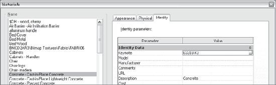
A powerful way to ensure consistent use of notes throughout your office is to create a master .txt file for your various project types. These master note lists can be prelinked to materials or assemblies within your project template, allowing you to immediately begin inserting common notes into any project. Prelink these settings by opening the Materials dialog box from the Manage tab and clicking the Identity tab. In the Keynote field, a predefined note can be added to any material.
Since the keynote .txt file is separate from the Revit file, if you send a project file to someone and don't send the keynote.txt file, that person will be able to see all the keynotes you've added to the views but won't be able to add or edit the notes without the .txt file.
The default .txt file in Revit resides in C:Documents and SettingsAll UsersApplication DataAutodeskRAC 2010Imperial Library (or Metric). To edit this file, open it in Notepad or Excel, and follow the format already established in the file. Let's look at that format to get a better understanding of how to customize keynotes.
The first few rows designate the groupings. They consist of a label (in this case, a number) followed by a tab and then a description. An example grouping looks like this:
03000 | Division 03 - Concrete |
Below the groupings, with no empty lines in the file, are the contents of the groupings. These are shown with a minor heading, a tab, a description, a tab, and the original grouping header. Here's an example:
03200 | Concrete Reinforcement | 03000 |
Here, 03200 is the subheading, Concrete Reinforcement is the description, and it all falls under the 03000 grouping from the previous example.
Using this method, you can add or edit notes and groups of notes to the keynote file. It might seem horribly inefficient at the beginning of the process to have to constantly go to the keynote text file to edit or add notes. Although this might seem like a burden, it can be a blessing as well.
Accessing this file ensures a level of consistency within the keynotes globally on the project that is unattainable in most 2D methods of drafting. If you are feeling frustrated with having to access this file to make changes, think about all of the time you are saving not having to check your set sheet by sheet to verify that all of the notes pointing to a material are consistent with each other.
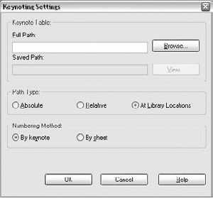
Once you change a keynote text file, you must reload the file into Revit to update the keynotes. Access the dialog box to change or update the text file by selecting the arrow in the Tag panel to access expanded panel options. Click Keynoting Settings to open the dialog box (Figure 10.43).
The Keynote Table group lets you define the path to the .txt file used for keynoting:
- Path Type
Defines how Revit looks for your
.txtfile using one of three methods:- Absolute
This option follows the UNC naming conventions and searches across your network or workstation for a specified location.
- Relative
This option locates the
.txtfile relative to the Revit project file. If you move the Revit file and the.txtfile, and they maintain the same folder structure, Revit knows where to look for them.- At Library Location
This option lets you put the
.txtfile in the default library location defined in the File Locations tab of the Options dialog box, accessed from the Application menu.
- Numbering Method
Defines how the keynotes are numbered:
- By Keynote
Allows you to number keynotes as they come from the associated
.txtfile.- By Sheet
Numbers the keynotes sequentially on a per-sheet basis.

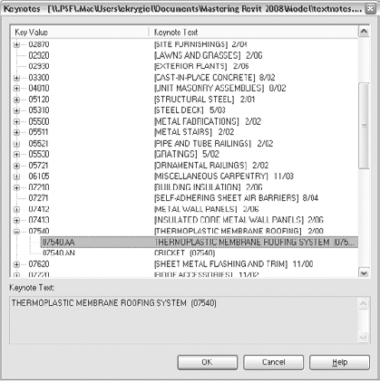
To add keynotes to a Revit model, choose one of the three keynote types from the Drafting tab in the Design bar. In your view, hover the cursor over the various model objects until you find the one you wish to note, and click to add the keynote to the element. Once you've placed the note, the Keynote dialog box will open (Figure 10.44), asking you to identify the element you're trying to annotate.

Expand the plus signs until you find your desired keynote, and double-click it. Doing so associates that particular note with the element or material in the model. As mentioned previously, you only need to make this association once. For example, if you keynote a material called Concrete, then every time you hover over that material anywhere else in the model with a keynote tag, you'll see the preview graphic of the tag showing Concrete (Figure 10.45). This way, you can define the materials and assemblies in the model and begin your documentation process.
With the exception of detail components (covered later in this chapter), you can't keynote lines or other 2D information.
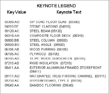
Depending on your workflow and style of annotation, you may want to create a legend for your keynotes that appears on each sheet so that the legend only shows the keynotes used on that sheet. Or you may want to have one legend for the entire project and show all keynotes used in that project in one legend. These legends allow the builder to reference the note number with the text quickly and easily (Figure 10.46). These lists usually reside on the side of sheets near the title block information and can take on one of two forms: inclusive or exclusive.
The first type is all inclusive and will show every note used in the project. This style has the benefit of being totally consistent from sheet to sheet. The same note will always be in the same location in the list. The other type of keynote list shortens the list to only contain notes present on the specific sheet. This has the advantage of supplying a list of notes customized for each sheet without extraneous information. As you can imagine, this second list can be labor intensive and fraught with opportunities for human error. One of the beauties of Revit is its ability to accurately manage this kind of information for you. We will review how to create both styles of lists.
Creating a legend in Revit is simple: open the View tab, then choose the Legend drop-down list and select Keynote Legend. You'll be prompted to name the legend; enter a name, and click OK.
Only two fields are available in a keynote legend, and by default, they are both loaded into the Scheduled Fields panel of the Fields tab in the Keynotes Properties dialog:
- Key Value
The numeric value of the keynote
- Keynote Text
The text value for the keynote

This legend works very much like any other schedule as far as formatting and appearance are concerned. By default, the sorting and grouping is already established by using the key value to sort. The one special item to note is located on the Filter tab. At the bottom of this tab is a feature unique to this type of schedule: a Filter by Sheet check box (Figure 10.47). Checking this box will give you the ability to filter the list specifically for each sheet.
Both styles of legend can be placed again and again on every sheet in the project. With the filtered legend style, it will dynamically modify the note list based on each sheet and the contents on each sheet. As views are added or removed from a sheet or notes are added to the project, the keynote legend will update accordingly. So, if the keynote is not used in the view placed on the sheet, it will not show up in the legend.

You will see all keynote legends listed in the Project Browser under the Legends node (Figure 10.48).
Revit comes with a keynote family that allows you to produce both keynotes and textnotes. If it is not loaded into your project, you can find it under the Annotations folder of the Imperial or Metric libraries. The family name is Keynote Tag.rfa. This family has three family types that allow you to change note styles within the project. You can see the three note styles in Figure 10.49.
The three styles are Keynote Number, Keynote Number — Boxed, and Keynote Text. Each of the notes shown in Figure 10.49 pulls information from the same text file that we discussed earlier in this chapter. You are simply using the flexibility of family types to report different values within the model from the same note. As with any other family, you can edit this family to change the note length, font style, or other attributes to match your office standards.
As we discussed earlier in this chapter, there are three styles of keynotes: Element, Material, and User. With all of these styles, there are limits to what you can note within Revit. Understanding this is critical to successfully using the keynote system so you can optimize the value of your predefined notes.
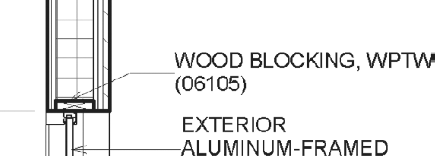
Nearly all model elements in Revit can be keynoted; the only exceptions are detail lines, imports, and groups. This becomes a critical issue when you begin embellishing details within a model, drafting them in 2D with a drafting view, or importing standard details from CAD and looking to add keynotes to the CAD drawing. As a best practice, we recommend using detail components and embedding them into project families. Detail components are families created with 2D lines that can be dropped into any view to represent elements that are not modeled as 3D objects. An example would be blocking that appears over a window head. This is not something you would create as a model element, but it is still necessary to show in a section or detail (see Figure 10.50).
Once you've established your keynote style and made your adjustments to font size and type, it's time to add some notes to the drawing. Adding notes to a drawing from this point is quite simple:
From the Tag panel on the Annotate tab, choose the Keynote tool.
Select Element, Material, or User from the drop-down list. For our example, select Material.
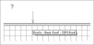
Move the cursor over the model — as you mouse over materials, Revit will try to identify what material is being used. If the material already has a note value defined, a floating note identifying the material will appear (Figure 10.51). From here, click to place the arrowhead on the note, click again to locate the joint in the leader, and then click again to locate the text. If the material is unknown, Revit will display a question mark to tell you this material has not been identified in the project yet (Figure 10.52). Locate the note using the same method for materials that are already defined. Revit will then prompt you to select a value from the Keynotes table (Figure 10.53).

Once you've selected the note for a material, that same note will be applied every time you select that material with a keynote in every other view within the project.
By default, Revit does not include an arrowhead with any of the keynotes. There is no way to preset arrowhead styles for any of the notes. After you first insert a note into Revit, you will have to select the note to add an arrowhead. To do this, select the note, open its Element Properties dialog box, and select Edit Type. Here you can globally set an arrowhead style for any of the keynote family types. Most of the common arrowhead styles can be found in this properties dialog box. Selecting one from the list shown in Figure 10.54 will change the arrowheads for all of the notes of that type within the project.
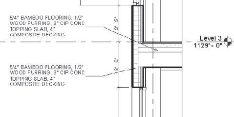
Once you've added a couple of notes, it's an easy process to continue noting the remaining materials in the wall section. The completed section with keynotes looks like Figure 10.55.

Another way to keynote a drawing is to note by element. Keynoting by element means that you are not noting the individual materials, as we did in our previous example, but the entire element assembly at once. So, in lieu of noting individual layers of plywood and gypsum board, you are noting the entire wall assembly. The process to add the notes is similar:
In the Tag panel on the Annotate tab, choose the Keynote tool.
Select the Element option from the drop-down menu.
Move your cursor over elements in the model, and Revit will try to identify the element or assembly. If the element already has a note value defined, a preview note identifying the element will display. From here, click to place the arrowhead on the note, click again to locate the joint in the leader, then click again to locate the text. If the element is unknown, Revit will display a question mark to tell you this element has not yet been identified in the project. Locate the note using the same method as for elements that are already defined. After you set the text location, Revit will prompt you to select a value from the Keynotes table.
A wall section noted by element looks like Figure 10.56.
There are a variety of other ways to add notes to a project without adding them directly in a view. Within the properties of elements and materials is a field to predefine a keynote. Putting a value in this field before annotating the drawings allows you to avoid selecting notes from the keynote list when you are actually annotating a view. All of the notes would be preselected. Depending on the note type, the location for these settings varies.
- Element
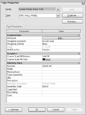
This value can be set in the properties of the various families in a Revit project. By selecting a wall, for example, you can open this wall's properties, and then click Edit Type to reach the wall type properties. Under Identity Data, you can then define a keynote (Figure 10.57). Selecting this field, you will be presented with the same Keynote table that you'd receive if noting this element in a view. If the note is incorrect for this project or element, you have the option to change the note here as well.
- Material
This value can also be set in the Materials dialog box. By selecting a material from this list and then clicking the Identity tab, you can add keynote values directly to your materials (see Figure 10.58). You will again be presented with the familiar Keynote dialog box to select your materials.
- User
User notes are view specific and cannot be predefined. While it is still only possible to annotate model elements and detail components with the user notes, this tool will allow you to note the same element with different notes in separate views. This can be dangerous to the consistency of your notes in your drawings if used inappropriately. The advantage to this note type, however, is if you need to note something differently in one view based on a unique condition. Some examples might be a material or color change in a special location, or a special flashing or sealant issue around a unique window condition. This means you don't have to re-create a new family type simply to add a different note.
Note
Revit does not support more than one keynote.txt file per project. So if you want to include keynotes from different standards, you can simply add more to the one .txt file that you have, and they will all be available to be used.