In previous chapters, we discussed how to create a model in Revit and how to make standard views to represent the model. We've explored how to create plans, sections, callouts, elevations, and 3D views of a BIM model. This chapter starts by looking at the properties of views and what these all mean. We then move on to sheets, and explore how to get your views onto sheets. In Revit, getting your views onto sheets is extremely easy: you simply drag and drop views from the Project Browser onto sheet views. Because every view has a scale, you see the effect immediately, and if you have to change scale or crop the view, you can do so in the context of the sheet. You can then print, export, or publish these sheets for use.
Topics we'll cover include:
Documentation trends
Preparing views
The sheet
Historically, the creation and delivery of document sets has been divided into three phases: schematic design, design development, and construction documents. The final CD set becomes the legal documents of record and is used by the contractor to physically build the building. With the advent of BIM, a discussion is taking place in the industry about this traditional division of documents, and new questions are being raised. Is this a viable and sustainable practice in the context of a BIM workflow? Can a BIM model redefine the types of documents that are created throughout the life of a project? Do we even need paper documents to build the building, or could a live, up-to-date BIM model actually be the deliverable? The divisions in BIM aren't as rigid as they have been in a legacy 2D workflow. An example of BIM deliverable packages might include:
Conceptual model and documents, where the basic geometric forms of the building are created
Design-development model and documents, where the building geometry and major building elements are completely modeled
Construction model and documents, where the design-development model is embellished with annotations and dimensions and the construction document set is created
This is more than just an elimination of schematic design. It amounts to a restructuring of project deliverables and more specifically, the deliverable timetable. The traditional percentages of time per phase also no longer apply. This is an important point to remember as you move forward in documentation, because you'll need to adjust your expectations and timeframe to a different delivery methodology. You'll find additional information in the Integrated Practice and Technology in Practice sections of the American Institute of Architects (AIA) website (www.aia.org/contractdocs/AIAS077630 and www.aia.org/TAP, respectively.). Recently AIA has produced a guide: Integrated Project Delivery: A Guide, www.aia.org/ipdg.
We are confident that this is a trend that will be followed worldwide.
Now that we've covered most types of views you can create with Revit, let's discuss how to place those views on sheets (Figure 9.1). But before you start placing views onto sheets, it's important to know about some critical properties of views that affect how they behave when placed on sheets. Preparing views so they look correct can be done at any time in the process — either before or after placing a view onto a sheet. The way a view looks is largely based on properties of the view, so we'll start there.

There are several ways to access view properties. You can get to the View Properties dialog box in any of the following ways:
Right-click any view in the Project Browser, and choose Properties from the context menu.
Right-click in the active view window, and choose View Properties from the context menu.
Right-click any view once it's placed on a sheet, and choose Element Properties from the context menu.
Select View on the sheet and use the Element Properties button in the Ribbon.
Select a view (click it with the mouse) in the Project Browser, and click the Element Properties button in the Ribbon.
Activate a view on the sheet using Activate View, and then use the keyboard shortcut (VP) to go to the View Properties dialog box.
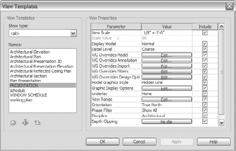
Like any other element in Revit, views have their own properties. Many of these properties can be displayed as parametric information about the view when views are placed on sheets. The information from a view can be directly reported in intelligent view titles, making coordination of data automatic. Other parameters control how the model is displayed graphically. Here is a list of common properties (Figure 9.2) and how they affect the view:

- View Scale
This sets the view scale of the drawing. You can similarly set the view scale in the View Control bar in the view window.
- Scale Value
This sets the drawing scale of the view that will be represented on the sheet.
- Scale Value 1
This field is noneditable for the view properties. It shows what your scale value would be if it were translated to an AutoCAD paper space view. This field dynamically changes as you change the View Scale value above it.
- Display Model
This determines how to show (or not show) all model elements of the view. There are three settings for this field: Normal, As Underlay, and Do Not Display. In Normal, the view is unchanged from its normal graphics. As Underlay grays out all the model contents in the view — it doesn't gray out 2D information like annotations, text, or dimensions. Do Not Display turns off all the model data and shows only the 2D information in the view. This would be used in detail callouts where all the lines are 2D, and not from the model.
- Detail Level
This offers three choices: Coarse, Medium, and Fine. Choose one depending on the level of detail you're trying to show in your model.
At larger scales, such as ¼″ = 1′-0″ (1:50), set the detail level to Coarse. Typically, plans or sections are printed at medium or fine, but at this scale lines are so close together that they can't be differentiated on the sheet. Also, a medium or fine setting on a complex model can drastically affect load time or print time of that view.
- Detail Number
This sets the detail number (such as A1) on the sheet. This number must be unique to each sheet.
- Rotation on Sheet
This setting gives you the option to rotate the view and view tag to read from the right side of the sheet rather than from the bottom. You might use this preference if you had a tall building and wall sections didn't fit in a traditional orientation. Note that you're rotating the view, not the model. Once a view is on a sheet, it can be rotated using the Options bar when the view is selected.
- Visibility/Graphics Overrides
This is an alternate way to access the Visibility/Graphics Overrides dialog box for this view. This dialog box controls which elements appear in the view.
- Model Graphics Style
This controls how your model displays on the screen. By default, it's set to Hidden Line. Other choices are Wireframe, Shaded, and Shaded with Edges. These options are discussed in Chapter 3, "Views."
- Graphic Display Options
This option brings up the Graphic Display Options dialog box, which controls shadows and shading. You can also access this dialog box through the View Control bar at the bottom of the view window.
- Underlay
This option lets you choose another level of the building to be shown in a light gray tone as an underlay to this view. This is useful if you're trying to align walls with a floor below or when you want to make a reference to a roof from the level above.
- Underlay Orientation
This option is available only if you've chosen to put an underlay into your current view. You can set whether you want to see the floor plan or the ceiling plan of your underlay.
Note
Underlays are thought of in the 2D drafting world as a layer of trace under your current drawing. This view is useful for seeing what is happening in another view while working in your active view. In a 3D modeling world, this underlay is a live look at the model — if you delete something shown as underlay, you're deleting the element, not an abstraction.
- Orientation
The model is typically shown orthogonal to the view you are working in, and this extends to how the view will appear when placed on a sheet. However, in many conditions a building doesn't align with the cardinal directions of your screen and printed page. Orientation lets you align your view with either the project north (screen and sheet north) or with true north (how the building is located relative to the earth).
- Wall Join Display
This property is only available in plan views and offers two options: to clean up all wall joins or to clean up the same types of wall joins.
- Discipline
This sets the discipline (architecture, structure, mechanical, electrical, or coordination) of the view in the document set. This is useful for sorting views in the Project Browser.
- Color Scheme Location
This puts color fill in either the foreground (in front of model elements) or background (behind model elements).
- Color Scheme
This adds a color scheme to the view, and allows you to edit an existing color scheme. Use this to create color-coded plan views. This parameter is available in plans, sections, and elevations, but not for reflected ceiling plans or 3D and perspective views.
- Dependency
Views that are made as dependent views report which view they depend on. A dependent view displays the annotations of the parent view. If a view is not dependent, it's listed as independent.
- Title on Sheet
This field allows you to override the name of a view as it appears on the sheet. By default, or if this field is left blank, Revit will make the name on the sheet identical to the name of the view. This is particularly helpful if a name on a sheet is not unique from other views — for example, if many views are simply titled "Detail."
- Annotation Crop
This enables a second crop region that only hides and unhides annotations that are outside of it or intersecting it.
- Sheet information
The following four fields in the view properties are noneditable in this dialog box:
Sheet Number
Sheet Name
Referencing Sheet
Referencing Detail
These values are reported from other views in Revit. Sheet Number and Sheet Name can be modified from the sheet they reference and tell you what sheet this view has been placed on. Referencing Sheet and Referencing Detail report which views this sheet references from. In the case of our example plan, we're referencing an elevation on sheet A200.
Note
If multiple references depend on one view, the first reference created is reported in the View Properties dialog box.
- Default View Template
This sets the default view template for this view. Creating and editing view templates is covered later in this chapter.
- Crop Region
This option activates the crop region for a view, which limits the extent of what is visible in the view.
- Crop Region Visible
This setting makes the crop region visible or invisible for the view. Under some circumstances, it can be a good idea to keep the crop region visible to ensure the size of the view doesn't change. The crop region can be hidden in the print dialog box, so you don't have to worry about printing boxes around all your views.
- Annotation Crop
This shows the crop boundary of a parent view when views are linked.
- View Range
This opens the View Range dialog box discussed in Chapter 3.
- Associated Level
If the view is associated with a particular level (in the case of a floor plan or enlarged plan), it's reported here. This isn't an editable field.
- Scope Box
A scope box limits the extents of level and grids. If you have scope boxes defined, you can apply them to this view.
- Depth Clipping
This controls the depth of the Plan clipping and offers the options to not clip, to clip without a line, or to clip with a line.
- Phase Filter
This option lets you control which of the defined phase filters (basically, phase combinations) are implemented in this view. You can set the phase filters by choosing Settings → Phases.
- Phase
If you have phases set up in your project, you can change the phase visibility properties for the view here and set a specific phase, such as New Construction.
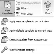
View templates are powerful time-savers when you're working on a project. The purpose of a view template is to capture view settings and then apply these settings to many views with the same graphical requirements. They are a great way to ensure graphical consistency between views. You can find view templates in the Graphics panel of the View tab, by clicking on the View Templates Settings button in the expanded panel for View Templates (Figure 9.3).
Different view templates tend to be used for plans, sections, elevations, and details. The View Templates dialog box allows you to create a new view template, delete, or modify existing ones. You'll notice that view templates are a subset of view properties. By setting these values, you can create standard view characteristics and push them into other views. In the View Template dialog box, you can preset the following view properties:
View Scale
Display Mode
Detail Level
Individual visibility and graphic overrides for model categories, annotation categories, imports, filters, and model graphics style
Graphic Display Options
Underlay
View Range
Orientation
Phase Filter
Discipline
Depth Clipping
With view templates, you have the ability to choose which parameters to include (or exclude) in the view template. For example, you may not want to apply a view template and have it change view scale or detail level, but still make changes to graphic style. To exclude a parameter, uncheck the desired parameter in the Include column.

Although it's possible to preset all your view settings through this dialog box, you may find it easier to select the settings interactively in a view. This way, you can see the effects of settings immediately. When you like what you've set up, you can then create a new view template from your active view. Right-clicking any of the views in the Project Browser gives you an option, Create View Template from View (see Figure 9.4). You can then apply this new view template to any other view. Applying a view template to a view is a single instance event. If you apply a template to a view and then modify the template, the view will not update to match those changes. You will need to reapply the view template to that view.
To apply a view template to another view, select one or more views (not sheets) from the Project Browser and right-click. Then, choose Apply View Template from the context menu. Choose the template you want to apply to the views and Revit will update them all to use the same view properties established in the template.
In this exercise, you'll create a new view template and apply it to a view:
Open the
Station_start.rvtmodel at the book's companion web page,www.wiley.com/go/introducingrevit2010, and open the view called Level 3 Pres. Note that there is already a Level 3 view, but this view has been set up to be a presentation-styled view. You want to create a similar view for Level 4.In the Project Browser, right-click the view Level 3 Pres, and choose Create View Template from View.
Name the view Plan Presentation. Click OK. The View Templates dialog box will open and the new template will appear in the list of view templates (Figure 9.5). From here you can make adjustments to the settings if need be.
Right-click the Level 4 view, and choose Duplicate with Detailing. Doing so creates a new view called Copy of Level 4.
Right-click the view called Copy of Level 4, and rename it Level 4 Pres. It resorts itself alphabetically in the Project Browser so it appears below the Level 4 view.
Right-click the new view, Level 4 Pres, and choose Apply View Template. Choose the new Plan Presentation view template from the list, and click OK.
Revit allows you to apply templates to schedule views as well. The workflow is the same as with any other view, allowing automatic propagation of graphic definitions from one schedule to other schedules in the project.
Construction documents are how architects convey their ideas and designs on paper to the contractor or builder so that they can build the building. The information conveyed must be sufficient and organized well enough for the builder to understand the design intent of the documents. Conflicts, errors, omissions, and coordination issues can and will occur on any document prepared by human hands. These discrepancies are magnified on the job site as cost overruns, RFIs, or lost schedule time. The goal of a good set of documents is to minimize the number of errors and convey the design clearly. Revit excels in this process by automatically managing your views and references and thereby eliminating many common errors found in traditional document sets.
Perhaps the mostly widely used type of architectural sheet system is the ConDoc system supported by the AIA. This system has identifiers for sheet name and numbering formats.
Most firms have a defined graphic standard for sheet layout. If you're responsible for creating office-standard content, such as sheets, you should take a bit of time to create Revit sheets that mirror your firm's standards before you get started on a project. Not only will you then have them when you're ready to go forward into production, but you'll gain experience working with Revit families.
Before you load a sheet into your project, notice the sheet border. In the title block exercise in this section, the border is an invisible line that traces the extents of the sheet. If you move your mouse over the outside border of the sheet, the invisible lines highlight. Invisible lines are a line type that is similar to a nonplot line; they don't graphically interfere with the view on the screen.
Title blocks in Revit are similar to any other family. You can create and edit them with the Family Editor. Like tags, title blocks use intelligent labels built into the family to pull data from the Revit model and apply it to the title block. This can be in the form of the view scale, project name, project address, or any parameter you see fit to use in your title blocks. To get an idea of how these labels work, you'll add one to an existing sheet. This exercise presents a basic description of how to add labels and other data to your sheets:
Double-click the
Presentation - 11 × 17.rfafile found on the book's companion web page. The file automatically opens in the Family Editor.This is a simple 11″×17″ title block. As with any sheet, you can add as much or as little detail as you want. In this sheet, you'll add a graphic scale.

Click to drop the text in the desired location on the sheet.
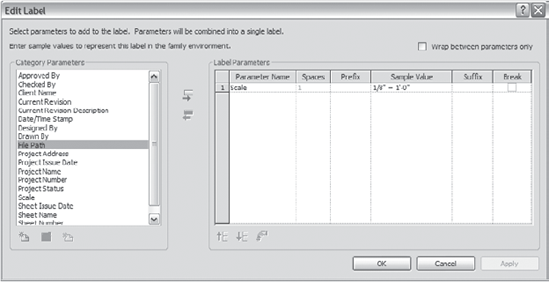
The Edit Label dialog box (Figure 9.6) opens and asks what kind of label you'd like to add. Choose a category parameter from the list, and then click the Add button

With this dialog box you can also add prefix and suffix values to the label, and even add more than one parameter to the label.

Add the prefix scale, and add a space after the word. Click OK.

This process adds a label to the sheet and shows its default value (in this example, ⅛″ = 1′-0″). As you bring views onto the sheet, this value parametrically changes to reflect the scale of the views on the sheets.
Note
Your sheet border may fluctuate depending on your printer type. For instance, an 11″×17″ printer typically has a print range of 10.5″×16.5″, or ¼″ margins around the edges. On some printers, printing at paper size can lead to minor distortion of the scale of the printed views. Depending on your printer type, you may need to set your sheet size to fit within the printer margins rather than set it to the actual paper size. Once the sheet has been created, you can load it into your project by clicking the Load into Projects button on the Family tab; or, in your project, you can go to the Insert tab, and from the Load From Library panel, select Load Family.
Revit allows you to add revision clouds and tags to sheets for tracking changes in the document set. These can be automatically tracked and displayed in a revision schedule on your title block. To place a revision schedule into a title block, follow these steps:
Open an existing title block family, or choose to make a new one.
In the View tab, click Revision Schedule. Click OK to accept the defaults, and then close the view.
Using the Project Browser, open the Schedules node. You will see a Revision Schedule view. Drag and drop this view into your title block.
To modify the graphics and fields used in the revision schedule, right-click on the revision schedule in the Project Browser and click Properties. In the Fields parameter, you can use common fields such as Revision Number, Description, Date, and Issued To (Figure 9.7).
When the title block is loaded into your project and you begin to add revisions to your project, the table will automatically fill up (Figure 9.8).
You can have revision tables that build from the bottom up. This is set in the Appearance tab of the Revision Properties dialog box (Figure 9.9). You can also set the schedule height manually, using the user-defined option. This allows you to graphically set up a blank table for your revisions (see Figure 9.10).


Note
To add revisions to your project, select the Manage tab and choose Settings → Sheet Issues/Revisions. In this dialog box, you can add revision information that will then show up in the revision schedule on your sheets. You can have revisions enumerate on a per-sheet basis or on a project-wide basis. When you add revision clouds to your sheets (from the Detail panel on the Annotate tab), set which revision it belongs to, and you'll be good to go.
A key component of a view placed on a sheet is the view title. These elements are tags that live on the sheet (see Figure 9.11) and display information about the view. Common information includes view name, scale, and detail number.
Note
View titles are families like every other element in Revit, but they have a slightly different access point for editing the graphics. You can edit most families in Revit on the fly by selecting the family and clicking the Edit Family button in the contextual tab that appears. However, some families don't show this button when selected. These include view titles, level tags, callout heads, and section heads. To edit one of these types of families, locate it in the Project Browser under Families → Annotations. Right-click the family, and select the Edit option from the context menu. Doing so opens the family in the Family Editor. Editing options are similar to those available for sheets (explained earlier in this chapter) and other tags.
The view title appears automatically when you place a view on a sheet. When you place the view, the labels are automatically populated with the correct information about the view. The detail number (in Figure 9.11, it's 1) automatically increases by 1 for each view placed on the sheet. (You can change this number to a letter, or a number–letter sequence, like A1.) If the view placed on a sheet is referenced from an elevation, a section, or a callout, the detail number is automatically propagated into the view markers in the other views. If you change the detail number, it updates the tags in the other views. Basically, this means that your references are always correct on any sheet and in any view. It's impossible for views to be out of sync.
Note
Detail numbers must be unique on each sheet. Revit doesn't allow for duplicates.
View titles are tags that report information about a view. If you select a view title on the sheet and open its properties, you'll see information about the view it is tagging. The element is called the viewport. From the type properties of the viewport, you can edit some graphic parameters for the view title such as color, whether to show the view title, and if the view title has an extension line.

If you don't want a view title to display on a sheet (as in a presentation drawing), duplicate the view title from the Type Selector, and set the view title properties to show no title and no extension line (see Figure 9.12). You don't need to create a new view title family for this purpose.
Take care when you modify the properties of a view title. Changing a view title type changes all the views on all the sheets of that type. That may not necessarily be the desired effect.
Placing a view onto a sheet requires a drag and drop from the Project Browser. You can drag views from the Project Browser onto a sheet name in the Project Browser, which will open the sheet view and let you place the view; or you can first open the sheet view, and then drag views onto the sheet from the Project Browser. If you don't have a sheet view set up, create a new sheet from the Sheet Composition panel on the View tab. Doing so opens a dialog box where you choose what type of sheet to make. Choose a sheet, and a new sheet view is created and opened. You can then start dragging and dropping any view name from the Project Browser onto the sheet (as long as the view has not already been placed on a sheet). You can place the view anywhere on the sheet, and it will be tagged with a view title.
With the exception of legend views, it's important to point out that you can't put a view onto more than one sheet. Each view is a unique, living picture of the model. Although this may not seem intuitive at first, it makes sense given that all views are guaranteed to report correct information about what sheet they're on. Every view placed on a sheet has a unique reference describing name and position on sheet. Schedules may also be placed on multiple sheets.
But what do you do when you still need to place the same view or a portion of the same view on two sheets? For this purpose there is a special type of a view in Revit called a dependent view. This lets you create a duplicate of the view that can then be placed on another sheet. This dependent view will follow any change of the original view and the two will be identical. For more details, see the section "Splitting Views across Multiple Sheets," later in this chapter.
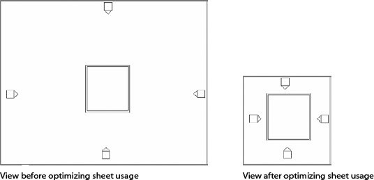
If views placed on a sheet don't fit in the space you have available, there are a couple of ways to mitigate the situation. The size of the view relative to the sheet is based on two things:
The view scale determines the architectural scale and can be modified from view properties, or the view controls. In most cases, the scale is correct, but the overall size of the view may be too large. If this is the case, there are two ways to solve this problem.
First, you can move annotations and symbols closer to the model, and tighten up the graphics to reduce the amount of empty white space. This approach buys you some precious sheet real estate. See Figure 9.13 for an example.
Moving a view marker is different from moving the view itself. For example, you can move an elevation symbol by grabbing the view tag without moving the front clipping plane of the elevation. In Figure 9.14, the physical extent and location of the elevation remain the same, but the tag has been repositioned.


Section marks behave in similar fashion. The blue controls at the base of the head and tail graphics let you make the graphic footprint of the symbol smaller or larger without affecting the extent of the view it's referencing (shown as dashed lines in Figure 9.15).
The second option to make your views fit on the sheet is to modify the view's crop region. Turning the crop region on and off was discussed in detail in Chapter 2, "Getting Acquainted with the Revit Interface and File Types."
Modifying the crop region changes the actual size of the view and can also hide areas you don't want to show on a particular sheet. In Figure 9.16, the crop region is described by the lines bordering the view. Although there is much more to see of the model at this floor, the crop region has been minimized to show only this unit. By drawing in the crop boundaries, you can make the view smaller to display only the information necessary for that view.

From the sheet view, you can edit views directly in order to make changes to the view in the context of the sheet layout. Select any view on a sheet, and either right-click to bring up the context menu, or click the Activate View button in the contextual tab. Selecting Activate View grays out the sheet and other views placed on the sheet and lets you directly edit the view as if you had opened the view normally. You can then manipulate annotations, model data, and the crop region. When you're done editing the view, right-click in the view to bring up the context menu, and choose Deactivate View. This drops you back into sheet view.
Note
While you're creating documents, you may decide to move a view to a different sheet than the one it's on. To do so, grab it from the sheet list in the Project Browser, and drag and drop it to the new sheet name in the list.
Revit has a specifically designed tool that allows you to split a view that is too large to fit on a single sheet, across multiple sheets. Using the duplication method called Duplicate as Dependent, available when you right-click a view title in the Project Browser, you will be able to make duplicate views that relate to one another so that you can work in one primary view and have your work appear in other, dependent views.
To understand this, let's review in more detail the three methods of duplicating a view that we touched on in Chapter 3. Right-clicking on the view names of a view in the Project Browser will give you three duplication options:
- Duplicate
Makes an exact copy of the model elements in a view and ignores any annotations and view-specific detail work existing in the original view. The resulting duplicated view will have no annotations or details in it. It will, however, show 3D annotations such as levels, grids, and reference planes. You will select this method of duplication when you need to make a presentation drawing of a plan in which you do not wish to see any dimensions, tags, or text existing in the original view. This method is applicable when you need to produce nice images of a project for publication purposes or marketing material ordered by your client.
Model changes that happen in either the original view or in the duplicated view will propagate to the other. Annotations added in either of the two will not propagate to the other view.
- Duplicate with Detailing
Makes an exact copy of the model, annotations, and detail elements. The new view will look exactly like the original. You use this method when you wish to continue developing a plan to a different level of detail than the original. Examples for this would be when you need to make a detailed plan of a typical hotel room from a hotel floor or a technical detail of a how a column penetrates a wall, and so on.
Model changes that happen in either the original view or in the duplicated view will propagate to the other. Annotations added in either of the two will not propagate to the other view (Figure 9.17).
- Duplicate as Dependent
Makes an exact copy of the model, annotations, and detail elements. This type of duplication also maintains a dependency between the view that is duplicated and the original view. If an annotation is deleted in either view, it is deleted from both views. Any changes that happen in either of the two views (the original or the duplicated view) will propagate.

Use this method when you work on very large projects when the plans you want to print in a certain scale do not fit the maximum sheet or plot sizes. In this case you'll split the plan in many portions, but they'll maintain the dependencies with the other parts so they are all coordinated in both model and annotation aspect. Another scenario is when you need to place the same view on different sheets. Note that when we say same, we really mean same: you cannot change scale or any other view properties of a dependent view and not have these propagate. The only allowed and possible differences between dependent views are per view visual and graphical overrides (hiding an element or category or graphically overriding an element or category).
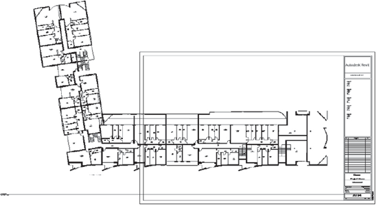
You have a large project and you wish to create a sheet with your floor plan. You open a sheet view and drag the floor plan on the sheet. You realize that the plan is too big for that sheet and that splitting it into separate pieces will be necessary.
You choose the Duplicate as Dependent option on the original floor plan. If you need to split the view in order to fit the plans onto more than one sheet, then duplicate as many views as you think you need. In Figure 9.18, two dependent views will be needed but as you can imagine, in bigger projects this could range from to six to eight dependent views. Figure 9.19 clearly shows that the entire plan will not fit on the sheet size of choice for the scale selected by the user.

Figure 9.18. The Dependent view functionality allows you to split views and place them on separate sheets
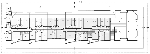
After creating duplicate views as dependent views, each view is cropped so that it will fit the sheet. You will notice with dependent views that the annotation crop is enabled by default. This is to keep annotations from other parts of the parent view from showing up in your cropped view. After manipulating the crop region of both views, you will end up with two dependent views, each focusing on one section of the building, as shown in Figure 9.20.
Note the double crop region: the outer boundary is the annotation crop; the inner is the model crop. When you drag the blue grips of the model crop, the annotation will follow along at a preset offset distance. Manipulating just the annotation crop has no effect on the model crop, and you cannot drag the annotation crop inside of the model crop.
If you go back to the original view and click the Show Crop Region toggle

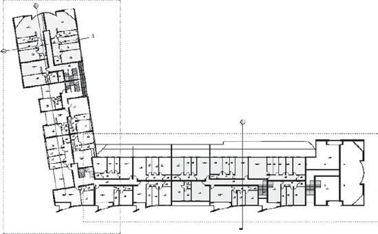
In our example, and this can be quite typical, one wing of the building (see Figure 9.22) may be at an oblique angle relative to the screen, and by extension, the sheet. Revit provides a way to orient each dependent view so that it can better fit a sheet.
To accomplish this task, in sheet view activate the dependent view, select the crop region of the dependent view, and rotate it. Figure 9.23 shows the process of rotation of the wing. During the rotation, you will notice a help line that finds angles of reference and can help you rotate the view parallel to the main axis of the wing. Figure 9.24 shows the rotated wing.
You can accomplish the same rotation by opening the dependent view itself and then rotating the crop region. Do not attempt to rotate dependent view crop regions from the original (parent) view.


You will also notice that rotating a dependent view reorients the tags in the view so they remain readable on the sheet (see Figure 9.25).

Whenever you are in any of the dependent views, you can see the other view by selecting the Crop View/Do Not Crop View option in the View Control bar
As you continue working with a project divided among multiple dependent views, you will notice that any addition or change to annotation as well as model elements will appear in all views associated with the original parent view.
One very neat detail: imagine your project has 20-plus floors and the size was such that you needed to divide it into four dependent views. After you have spent time dividing the first four on Level 1, you need to do the same thing for the remaining floors. Revit streamlines this process for you. In the right-click menu of the parent view that you made the dependent views from, there is an option called Apply Dependent Views that will open a dialog box. You can use this dialog box to select all the views you want to apply the same dependent view division to. With one click, this will create many dependent views.
Match lines are graphic indicators in plan views that depict a split in the drawing because the whole building could not fit on a sheet (Figure 9.26). In Revit, the match line is a 3D line that extends (as grid lines do) through the entire project.

The Matchline tool can be found in the Sheet Composition panel on the View tab and is drawn as you would any other line in Revit. In the properties of a match line you can define the top and the bottom constraints. This is needed when the building does not have the same floor plan through all floors, and the break line for dependent views might not be applicable to all views in the same way.
View references are a special type of annotation applicable to views only. They reference other dependent views and hyperlink to them.
You will find the View Reference tool in the Tag panel on the Annotate tab. If you are in a dependent view and select a view reference, it will instantly recognize the other dependent view and create a reference and hyperlink to it. If you are in the original view when more dependent views are present, you can select the View Reference tool, hover the cursor over a crop region of a view you want to reference, and place the view reference.
Note that the view reference will be empty if the dependent view is not placed on a sheet. The moment you place it on a sheet, it will fill in the number of the reference (Figure 9.27).

A few more tips about dependent views:
When you select Duplicate as Dependent View, the dependent view will appear as a node under the original view in the Project Browser.
A dependent view can at any point be converted to an independent view. You can do that in two different ways:
Right-click on the dependent view and select Duplicate with Detailing. This will keep the dependent view and create a new independent view.
Right-click on the dependent view and select Convert to Independent View.