Once you've started modeling with Revit Architecture, you'll probably need to make changes to the model as your design evolves and becomes more refined. You'll need to move, mirror, and array elements; change properties of elements; apply different graphics to various elements; and even hide and unhide elements. This is where the editing tools and graphic override features come into play. The basics of these tools will be explained in this chapter.
This chapter reviews the essential modification tools available in Revit. Topics we'll cover include:
Standard editing tools
Additional editing tools
Graphic and visual overrides
This section describes some of the standard editing tools in Revit. For each of these tools, you first need to select elements, and then invoke the appropriate command:
Copy, paste, and cut
Move
Copy
Rotate
Array
Mirror
Resize
Copy, paste, and cut are familiar tools used in almost all software applications, and Revit has the basic shortcuts that you'd expect for these interactions (Ctrl+C for copy, Ctrl+V for paste, and Ctrl+X for cut). It also has some surprising timesaving options that you can use when you're pasting elements that are driven by the nature of a building model.
To copy any element to the clipboard, select it and press Ctrl+C to copy or Ctrl+X to cut. Elements are now ready to be pasted. To paste, press Ctrl+V. In the majority of cases, Revit will place your selection on your cursor, with a dashed box that represents the size of the bounding box containing your to-be-pasted elements. Clicking anywhere in the model will place the elements.
In addition to the familiar copy and paste tools, Revit offers some other paste options that can be used with elements copied to the Windows clipboard.
Once elements have been copied to the clipboard, they can be pasted into other views with a variety of options. This allows you to quickly duplicate elements from one view to another (from one floor to another floor, for example) while maintaining a consistent location in the X–Y coordinate plane. After selecting elements and copying them to the clipboard using Ctrl+C, choose the Paste Aligned drop-down options in the Contextual tab, as shown in Figure 5.1.

Five options are available. Depending on the view from which you copy and what elements you copy, the availability of these options will change. For example, if you select a model element in a plan view, you'll have all the options shown in Figure 5.1. Let's look at all five options:
- Current View
This option pastes the elements on the clipboard in the currently active view, in the same relative spatial location. For example, if you copy a series of walls in a view, Revit remembers the walls and their location. Using this feature, you can copy elements from one view (level 1) and then switch to another view (level 2) of the same type and paste the elements into that view. This can be particularly useful if you'd like to copy walls and other elements between different floors. Open a restroom plan on one floor, copy it to the clipboard, open the second floor, and then choose Paste Aligned → Current View. This will duplicate those elements to the open floor plan in the identical location vertically.
Note
If you press 0 (zero) and then the Enter key, Revit will allow you to paste to the same XY coordinate.
- Same Place
This option places an element from the clipboard into the exact same place on the same level from which it was copied or cut. One use for this tool is copying elements into a design option. Design options allow you to iterate on multiple designs in the context of one file. They also allow you to save portions of the design while you manipulate other sections. Using this feature, you can "remove" portions of the project, make other changes, and then restore those elements cleanly to their previous location.
- Pick Level Graphics
You can use this option to copy and paste elements between different levels. Once you select the elements, you're placed into a pick mode, where you can select a level in section or elevation. You must be in elevation or section view to have this option available. The level you select determines the Z location of the paste and preserves the X–Y location. You might use this method to copy balconies on a façade from one floor to another in an elevation view.
- Select Levels by Name
This method is similar to the previous one, but the selection of levels doesn't happen graphically. Instead, you choose levels from a list in a dialog box and you can paste to multiple levels at once. This is useful when you have a multistory tower; in such a case, manually selecting levels in a view can be tedious. Similar to other options, the X–Y position is maintained, and the pasted elements are copied in the vertical dimension. This is useful for pasting groups on multiple levels simultaneously.
- Select Views by Name
This option lets you copy elements to other views by selecting views from a dialog box. A list of parallel views is provided, and you choose which views you want to paste the element into. For example, if elements are copied from a plan view, only other plan views will be listed. Likewise, if you copy from an elevation view, only elevation views appear as possible views to paste into.
Your projects will be changing constantly as the design takes shape and adapts to requirements. You will often need to move and reshuffle elements from one place to another, especially in the initial phases of a project. Thanks to parametric constraints in Revit, many objects move in relation to other objects in an automatic manner, but you also need the ability to move things manually. There are a couple of ways to accomplish this in Revit: using an explicit two-click Move command or using the keyboard arrows to Nudge elements.

When the Move command is active, several options are available in the Options bar:
- Constrain
When this option is selected, it constrains movement to horizontal and vertical directions. Use this to guarantee elements don't get placed off axis.

- Disjoin
Hosted elements such as windows and doors can't change a host (a wall, for example) and move to another host without explicitly being disjoined from their host. This tool allows that disjoin. If you need to move a door from one wall to another, select the door, select the Move tool, check the Disjoin option in the Options bar, and move the door to another host element.
- Copy
This option makes a copy of the selected element and then moves that copy to the desired location. The original element stays in place.
Use the nudge command when you need to move an element incrementally. Any time an element is selected, you can use the arrow keys on the keyboard to move the element horizontally and vertically in very small increments. Each press of an arrow key nudges the element a specific distance based on your current zoom factor. So, if you are zoomed way out, it will move elements farther than if zoomed in tight.
Note
You can also make copies of elements by selecting them, then pressing the Ctrl key and dragging your mouse. Once you release the mouse button, a copy of selected elements will be placed in the model. With this method, you'll see a preview of the element being copied, not an empty boundary box.
There are two ways to rotate elements in Revit: using the Rotate tool and using the spacebar.
To rotate an element, select it and click the Rotate tool. A round rotate icon indicates the center of the rotation and appears at the center of the element's bounding box (Figure 5.3). This icon can be repositioned to set the desired center of rotation.

More often than not, the center of the element isn't the point around which you want to rotate. If this is the case, you need to reposition the center of rotation. To do this, select the icon and drag it to the point you wish before rotating the element — this temporarily relocates the origin. Once the origin is established, begin rotating the element using the temporary dimensions as a reference or typing in the angle of rotation explicitly.
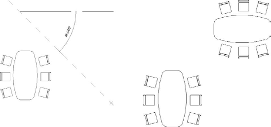
Many family components (furniture, casework, doors, windows, etc.) can be rotated in 90-degree increments by selecting the element, then pressing the spacebar (rotating with the spacebar also works during creation of an element). This is a quick way to lay out room configurations. If the element you are rotating is near a reference that is not horizontal or vertical (an off-axis wall under 30 degrees, for example), the spacebar will pick up that reference as you cycle through possible positions. Press the spacebar until you get the right orientation, then exit the command by either clicking the Modify button or pressing the Esc key twice. If you press the spacebar as you start to sketch a wall or after you select a wall that has already been sketched, the wall will flip with respect to its location line.
The steps to create an array depend on the settings on the Options bar (see Figure 5.4).
You can create two types of array: linear and radial. Linear is set as the default. A linear array puts a series of elements on a straight segment of a line; that line can either use a set distance between elements or equally space a number of elements over a given distance. The radial array works in a similar fashion, but it revolves elements around a center point.
The Group and Associate option lets you treat the array as a group that can be modified later to adjust the number or spacing of the array. If this is unchecked, then the array is a one-off operation similar to Copy, and you'll have no means of adjusting the array after you create it.
In the Number field, set the number of elements to be arrayed. This option is active when Move To: 2nd is checked. For example, if you type 7 as the number and check Move To: 2nd, the element will be arrayed seven times. The distance between elements is determined by the distance between two subsequent mouse clicks in the view.
Figure 5.5 shows two arrays drawn from A to B, number 5, illustrating the difference between choosing Move To: 2nd and Move To: Last.

In both examples, Group and Associate were activated. When an element in the array is selected (after the array has been placed), a numeric control similar to a temporary dimension appears, indicating the number of elements in the array (shown as a 5 in the center of the array in the previous figures). This allows you to change the number of elements in the array by directly editing the number. Revit will maintain an associated array as long as all the original members of the array still exist and are equally spaced. If you wish to change the position or delete just one of the arrayed elements, you will need to select the element, select Ungroup from the Options bar to deactivate (break) the association between the arrayed elements, and only then perform individual actions with that element.
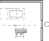
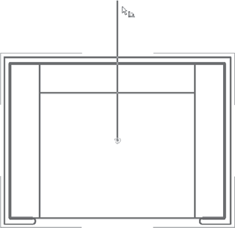
The Mirror tool allows you to mirror elements across an axis to create a mirror image of an element, like the chairs in Figure 5.6. This tool lets you either pick an existing reference in the model (the arrow icon) or draw the axis interactively (pencil icon).

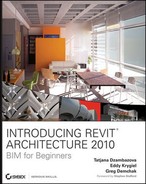
Use the pick method when you have an existing element with a meaningful center axis. If nothing in the model exists to pick as a mirror axis, use the Draw mode and draw your own axis, as shown in Figure 5.7.
Note
To mirror doors and windows in a wall, it is faster and more intuitive to use the spacebar or the blue flip arrows after selecting an element. You can of course also use the Mirror command, but the methods mentioned previously are specifically designed to address this.
Certain real-world objects are not meant to be mirrored, such as mechanical equipment, specialty equipment, and plumbing fixtures. These objects may look graphically correct when mirrored, but doing so may adversely modify the element's analytical data. For example, mirroring a piece of medical equipment may result in the mechanical engineer proposing utility connections at an inappropriate location. The same applies for doors.

The Scale tool is well suited for working with imported images that need to be scaled to match real-world dimensions. Say you've scanned a drawing of an existing building that you wish to convert into a model. Chances are, the image isn't at any reasonable scale when imported and needs to be scaled relative to some model element. Resize also lets you modify the relative size of a sketch created during Sketch mode, or a selection of lines or detail lines.
The Scale tool will become active in the Contextual tab once you select an imported image. After you select the tool, click a point to enter an origin (say, the left corner of the image); the second point you click is the width of the image that you want to fit within a certain size; finally, the third click is the new length you want (see Figure 5.8).
An additional set of editing tools is available in Revit for editing your design. You'll find them in the Edit panel on the Modify tab. From a workflow perspective, these tools work by first selecting the tool and then selecting the elements on which you want to perform operations.
When you're placing and dragging elements, Revit automatically creates temporary alignment lines to similar types of elements in the model. Use these alignment lines to place elements in relation to other elements. When you drag elements around, take note of these helpful alignment lines, and use them to line things up. This works for all categories of elements, including annotations. Figure 5.9 shows autoalignment lines when placing a tag.

These alignments are great for lining up annotations such as room tags. Select a tag and drag it — note how it aligns to other tags in the view, making it a snap to create organized drawings. Figure 5.10 shows the alignment lines while interactively dragging.

In addition to the alignment graphics, the Align tool is one of the favorites among Revit users. It makes lots of common manipulations easy and precise. The Align tool matches the edge of one element precisely to another. In some cases, this will move an element more accurately than measuring the distance that an object needs to move and then moving the object that distance.
Revit has embedded placement and can modify the alignment between elements of the same category. That is to say, when you drag elements around, they locate nearby similar elements, and alignment graphics are drawn to aid you when laying out the model or adding annotations. Figure 5.9 shows auto-alignment during tag placement.
If you wish to put room tags in order on your drawing, and you start moving one to align with another, Revit shows an alignment line and snaps to the other tag. Figure 5.10 shows auto-alignment during editing.
You can explicitly align references from one element to another using the Align tool. For example, you can align windows in a façade in an elevation view to line up their center lines. To use the Align tool, select a target line and then select what you want to align to that first pick. The second element picked moves into alignment. Whenever an alignment is made, a blue lock icon will appear. Clicking that icon locks the alignment, creating a constraint between the two elements. Once constrained, if either element is moved, both elements will move together.
Locking elements together is a powerful part of Revit. However, locking too many elements together can overconstrain your model. Be careful when you choose to use this tool and lock objects sparingly until you have a good grasp of the resulting constraints.
Figure 5.11 shows the use of the Align tool to align windows on a façade. The top window's mid-axis is selected as the alignment reference. After that, the mid-axes of the lower windows are clicked, and the lower windows automatically align to the top window.
The Align tool also works for aligning geometry with surface patterns like brick or stone. Figure 5.12 shows how you can align the edge of a window to an expansion gap.
The Align tool is useful in the Family Editor environment, where you can align an element to a reference plane that will control the behavior of that element and lock it.


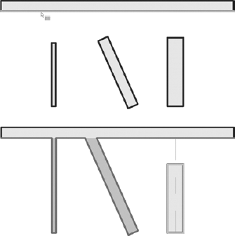
The Split tool is used only on lines and walls and is used to split these elements into separate entities. When activated, place the mouse over a wall or line. A knife icon will appear; clicking will split the wall or line into two separate segments. If you need to make two splits, with the intention of removing the segment between the two splits, click the check box Delete Inner Segment on the Options bar. See Figure 5.13.


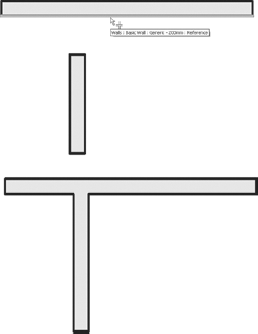
Figure 5.15 shows two walls before and after using the Extend Single Element tool.
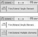
Figure 5.16 shows multiple walls before and after using the Extend Multiple Elements tool.
The Offset tool is similar to the Move and Copy tools: it makes a copy of a selected element parallel to the edge you select as a reference for offset. You can find the Offset tool either on the Edit tab or on the Options bar (Figure 5.17) when you're sketching lines or walls.
This tool is particularly useful in the Family Editor when you're making shapes that are a consistent thickness in profile, such as an extruded steel shape. Offset is also handy when you're making roof forms or soffits with known offsets from a wall. You can either offset a line and maintain the original (copy) or offset the line and remove the original. Figure 5.18 shows the offset of a loop of lines using the Copy option.
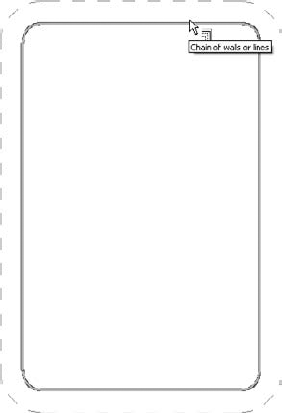
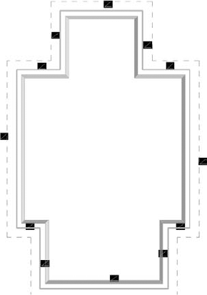
Figure 5.19 shows how you can use the Offset command to make the roof boundary wider in every direction.
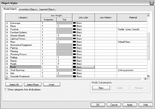
Revit provides a rich set of controls that allow you to change the graphic appearance of elements on a view-by-view basis. Every element belongs to a category, which provides a baseline graphic appearance for any given element. However, the category graphics may need to deviate, depending on what you're trying to convey in a drawing. For example, the furniture category uses a solid black line by default. Set this on Manage tab by choosing Settings → Object Styles. Changing the default values in the Object Styles dialog box affects furniture in all views, as shown in Figure 5.20.
Let's say you need to create a plan view where all furniture is shown as halftone, dashed, or hatched. No problem. With Revit, this is handled with view-specific graphic overrides that can be applied to entire categories or individual elements.
Each view is a unique view of the model that can be graphically tailored to meet your needs. Graphically overriding an element or a category doesn't mean you're changing the element — you're changing its appearance. To override graphics in a view, you can use the Visibility/Graphic Overrides dialog box or the view-specific element overrides dialog box:
To access the Visibility/Graphic Overrides dialog box, you can either go directly to the dialog box from the View tab, or right-click in the view and choose View Properties from the context menu. You'll see the Visibility/Graphics Overrides parameter in this dialog box as well.
You can also access the dialog box when an element is selected using the right-click menu. Select an element, and choose Override Graphics in View → By Category (Figure 5.21).
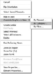
When you use the context menu, the dialog box preselects the category for you based on the elements you selected. For example, to override the furniture category, select a piece of furniture and use the right-click menu to access the override options.
Figure 5.22 shows a chaise lounge chair in elevation, in the default mode and with lines overridden using dashed lines.

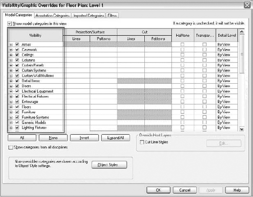
Once you're in the Visibility/Graphic Overrides dialog box, you'll see a list of all the categories and the various ways of manipulating the graphics. To get a handle on this, we'll walk through the override options from left to right, as they appear in the dialog box.
Top-level tabs divide elements based on type: Model, Annotation, and Imported. The Filters tab is also available as a way to manipulate graphics based on parameter criteria. If a view includes imported or linked files, there will be tabs for those as well, which will allow you to change the visibility and appearance of imported layers. This dialog box is powerful and allows for total control over the graphics of anything in your view.
The first column combines a list of categories and subcategories with a visibility toggle. To turn off the visibility of a category in the view, uncheck the box next to the category, as shown in Figure 5.23.
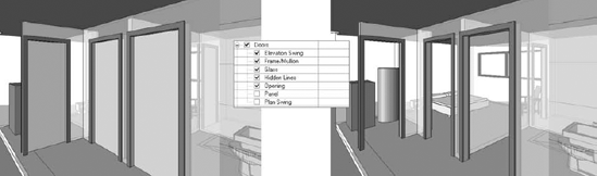
Each category has a list of subcategories; to turn off any particular subcategory, uncheck it.
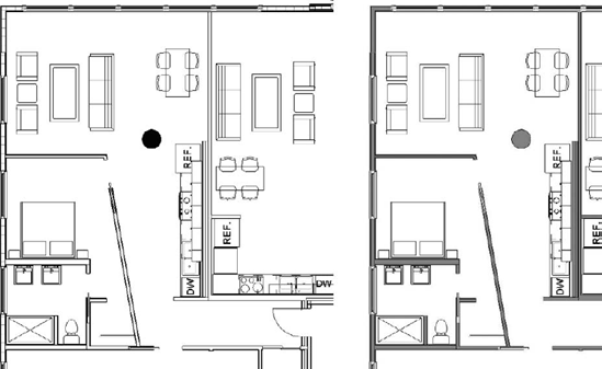
Figure 5.24 shows an example of controlling visibility by unchecking subcategories from the Visibility/Graphic Overrides dialog box. The first image shows the view with the doors turned on, the second image shows what subcategory is unchecked, and the final image shows the result.
The lines and surfaces of elements in projection can be overridden. With these controls, you can change the line style of any element and also apply hatches to surfaces.
For most model categories, you can apply overrides to projected and cut lines as well as surface and cut patterns (shown in Figure 5.25). Using these overrides allows you to alter line color, thickness, and pattern. You can also apply a hatch pattern override to any surface, whether projected or cut.

To add an override, click the desired override for the category you want to change. The row will then display a series of buttons, as shown in Figure 5.26.
Clicking Override takes you to dialog boxes where graphics can be overridden. Figure 5.27 shows the Line Graphics override dialog box and the Fill Pattern Graphics override dialog box. Note that the options in the dialog boxes vary based on what you're trying to manipulate.
The controls are fairly self-explanatory. Feel free to experiment with the behavior.

Note
Here's something important to know about the Fill Pattern Graphics dialog box: if you want to hide the pattern of a category, use the Visible check box in the Pattern Overrides options. Don't change the pattern color to white, because doing so can cause problems if you end up exporting the view. The lines are still there — they just don't appear, due to the screen background color.
These columns (shown in Figure 5.28) are check box controls that change lines and surfaces. The Halftone option takes the line color and tones it down by 50 percent. The Transparent check box makes all surfaces of the category 100 percent transparent, so that you can see through these elements in the view.
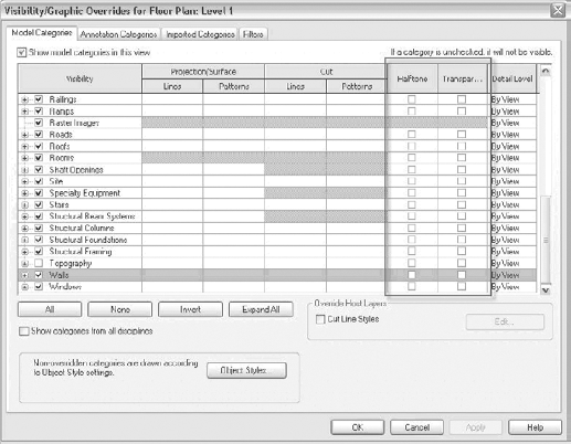
The last column controls the detail level appearance for categories. This allows you to show fine levels of detail for some categories, even if the view is set to coarse. Until you get into sophisticated content creation, this level of override can be safely ignored.
The Visibility/Graphic Overrides dialog box contains an additional override feature specific to layers that make up walls, floors, and roofs (in Revit terms, these are considered "host" elements). You can see it at the lower right: the Override Host Layers section. Using this edit control, it's possible to override individual layers within wall, floor, and roof elements. For example, this will let you make the structural stud layer of walls appear in a heavier line weight than the finish layer.
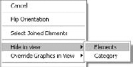
When elements are selected, you can hide them in the view and also override their graphics. This allows you to change the visibility of individual elements, not just entire categories. To do so, right-click any element, and then use the context menu option Hide in View → Elements, as shown in Figure 5.29. To unhide elements, use the Reveal Hidden Elements mode, located in the view control tools at bottom of the view. This will reveal hidden elements in a red color, and allow you to unhide them. When elements are selected, you can use the buttons in the Contextual tab to unhide them.
The selected elements are hidden in the view. Figure 5.30 shows an example of hiding only a few elements of a category in a view. In this case, the trees are obstructing the camera view, so a few of them have been overridden to improve legibility of the view.
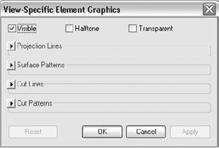
To override the graphics of a selected element, choose Override Graphics in View → By Elements from the context menu. Doing so brings up a dialog box with the same graphic overrides available in the Visibility/Graphic Overrides dialog box, but in a collapsed state (see Figure 5.31).
Along the top of this dialog box are check boxes for making an element visible, halftone, or transparent. Below that are groups of controls for overriding lines and patterns. Clicking the small arrow button opens and closes groups of controls for each kind of override. Figure 5.32 shows the dialog box with Projection Lines expanded.
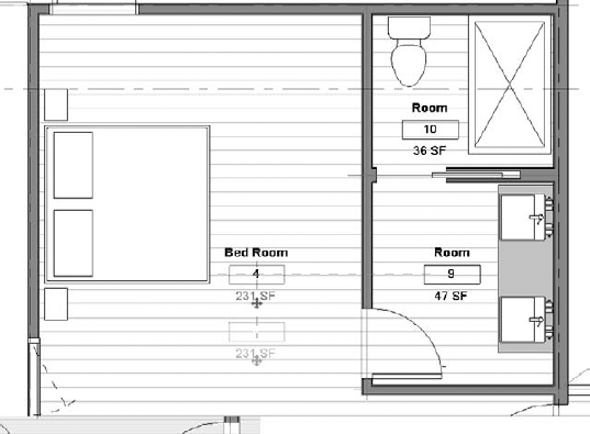
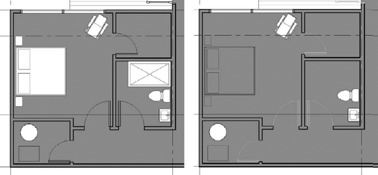
Figure 5.33 shows various element overrides; the bed is set to transparent, the doors to halftone, and the shower to invisible.
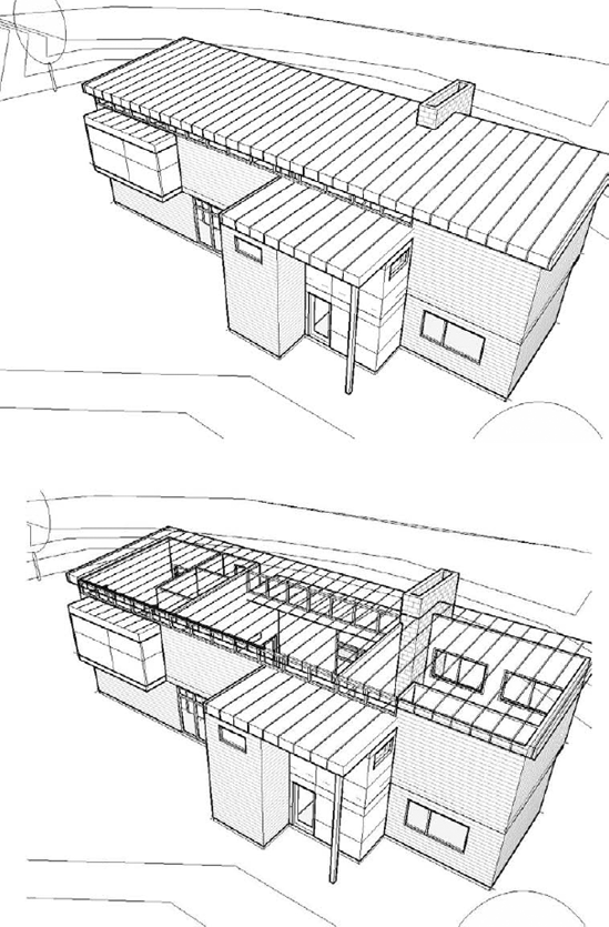
Figure 5.34 shows an example using a transparent override per element in a 3D view; the roof and the front wall are transparent.
Graphic overrides applied on a per-view basis allow you to quickly turn a working drawing into a presentation drawing. For example, you can override all elements that are cut with a solid fill color with a few simple clicks, to get another style of presentation drawing. Figure 5.35 shows how you can modify the color of the wall in a plan view.


After an element or category has been hidden, you can use the Reveal Hidden Elements toggle to see hidden elements and then unhide them. To do this, click the light bulb icon in the View Control bar.
The view halftones all visible elements and draws hidden elements with magenta color. A magenta border is also drawn around the entire view to make it more obvious that you're in a special mode. Hovering the mouse over hidden elements displays a tooltip that explains how the element is being hidden: Hidden Category or Hidden Element. Figure 5.36 shows some examples of hidden elements and categories.
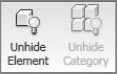
To unhide the element, use the buttons in the Options bar or the right-click option Unhide in View → Element. To reset the view to its normal display, click the light bulb icon again.
As you can see, Revit provides a full range of tools that give you control over how your model looks and feels. Using the interactive editing tools, you can manipulate elements spatially and then make decisions about how elements should be displayed, depending on what you're trying to convey with your drawings.
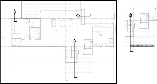
Figure 5.36. Hidden elements and categories